
Related Manuals for R.V.R. Elettronica PJRL250


Summary of Contents for R.V.R. Elettronica PJRL250
- Page 1 PJRL250 TECHNICAL AND MAINTENANCE MANUAL Manufactured by R.V.R. Elettronica - Italy...
- Page 2 PJRL250 Technical and Maintenance Manual PJRL250 POWER MOSFET AMPLIFIER 215- 225 MHz RANGE Technical and Maintenance Manual English Pag. 3 R.V.R. Elettronica S.r.l. (Bo) Pag. 2...
- Page 3 PJRL250 Technical and Maintenance Manual INDEX Preliminary Instructions and Warranty Information Pag. 5 Safety Regulations Pag. 7 SECTION 1 PJRL250 Description Pag. 10 Technical Specifications (Table A) Pag. 12 Dimensional & Environmental Specifications (Table B) Pag. 13 SECTION 2 Electrical Description Pag.
- Page 4 PJRL250 Technical and Maintenance Manual Telemetry Card (Ver. PROT-A2) Pag. 44 Power Supply (Vers. 1.7) Pag. 48 Soft Start Card Pag. 56 R.F. Module Pag. 60 Low Pass Filter & Directional Coupler Pag. 65 R.V.R. Elettronica S.r.l. (Bo) Pag. 4...
- Page 5 PJRL250 Technical and Maintenance Manual PRELIMINARY INSTRUCTIONS AND WARRANTY INFORMATION Please observe safety precautions when handling this unit. This equipment contains dangerous currents and high voltages. This manual is written as a general guide for those having previous knowledge and experience with this kind of equipment. It is not intended to contain a complete statement of all safety warnings which should be observed by personnel in using this or other electronic equipment.
- Page 6 PJRL250 Technical and Maintenance Manual To claim your rights under this warranty: Contact the dealer or distributor where you purchased the unit. Describe the problem and ask if he has an easy solution. Dealers and Distributors are supplied with all the information about...
- Page 7 R.V.R. ELETTRONICA S.r.l. shall not be responsible for injury or damage resulting from improper procedures or from the use of improperly trained or inexperienced personnel performing such tasks.
- Page 8 PJRL250 Technical and Maintenance Manual Treatment of electrical Shock 1) If victim is not responsive follow the A-B-C's of basic life support. PLACE VICTIM FLAT ON HIS BACK ON A HARD SURFACE A AIRWAY B BREATHING IF UNCONSCIOUS, IF NOT BREATHING,...
- Page 9 PJRL250 Technical and Maintenance Manual FIRST-AID Personnel engaged in the installation, operation, maintenance or servicing of this equipment are urged to become familiar with first-aid theory and practices. The following information is not intended to be a complete first-aid procedure, it is brief and is only to be used as a reference.
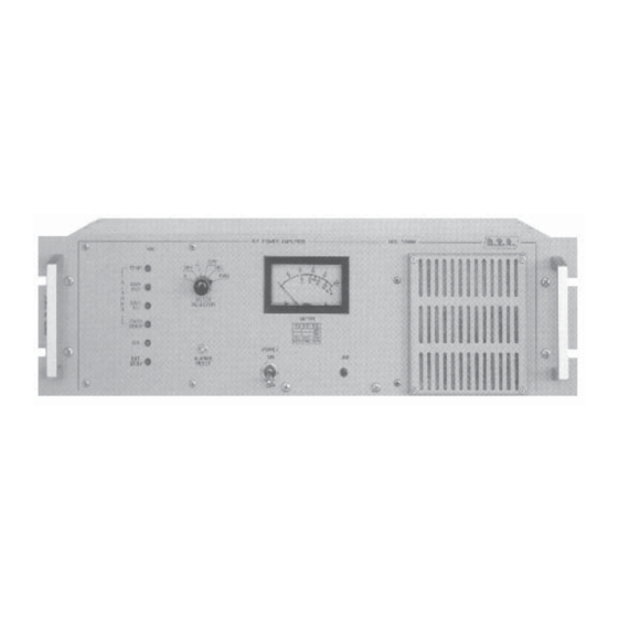
- Page 10 SECTION 1 PJRL250 DESCRIPTION 1.1 EXTERNAL DESCRIPTION The PJRL250 is housed in a 3U 19" rack completely assembled with modules fitted on main rails, wired with connectors allowing easy servicing and replacement. On the front panel the alarm indicators, the mains switch and the meter for the principal parameters.
-
Page 11: Protection Circuits
PJRL250 Technical and Maintenance Manual 1.5 PROTECTION CIRCUITS The protection circuits set the amplifier in stand-by in the case of a fault condition. After 10 seconds the protection reactivates the amplifier if the fault has disappeared. If not, this process is repeated 4 times at the end of which the amplifier stays disabled for few minutes;... -
Page 12: Technical Specifications
PJRL250 Technical and Maintenance Manual TABLE A TECHNICAL SPECIFICATIONS A.C. Supply 100-130 V, 50-60 Hz 198-250 V, 50-60 Hz Cooling Forced Ventilation Frequency Range from 215 to 225 MHz Power Output 250 W R.F. Drive Power approximately 10-12W for Pout=250 W R.F. - Page 13 PJRL250 Technical and Maintenance Manual TABLE B DIMENSIONAL AND ENVIRONMENTAL SPECIFICATIONS Cabinet Dimension 126 mm (04.96") H 437 mm (17.20") W 340 mm (13.39") D Panel Size 483 mm (19.00") W 132.5 mm (5.22") H Operating Temperature -10°C to 50°C...
- Page 14 2.3 R.F. POWER AMPLIFIER MODULE The R.F. power amplifier module (4 Photo 1) are placed in the right side of the PJRL250. This module is totally shielded and placed on a heat sink as shown Photo 1. The R.F. power amplifier module delivers 250W with 10W of drive and is supplied by an switching power supply.
- Page 15 PJRL250 Technical and Maintenance Manual 2.5 ALARMS CARD This module (3 Photo 1) is composed of a board mounted on the front panel, in left position, as shown in Photo 1. On this board, the electronics detect any system anomaly such as excessive SWR antenna (the internal SWR is not actived);...
- Page 16 PJRL250 Technical and Maintenance Manual FRONT PANEL VIEW DESCRIPTION (FIG. 1) EXT. ST. BY Led indicating an External Stand-By A.C. ON Power indicator ALARMS RESET Press-button to reset the alarm status ON/OFF POWER On/Off Power Switch LINE A.C. Line Indicator AIR FILTER Air filter of R.F.
- Page 17 PJRL250 Technical and Maintenance Manual FIG. 1 R.V.R. Elettronica S.r.l. (Bo) Pag. 17...
- Page 18 PJRL250 Technical and Maintenance Manual REAR PANEL VIEW DESCRIPTION (FIG. 2) Forced ventilation R.F. TEST -60dB -60dB with respect to the Output Level TELEMETRY CONNECTOR Connectors for remote measurement of operating parameters. R.F. INPUT Input R.F. connector ("N" Type) R.F. OUTPUT Output R.F.
- Page 19 PJRL250 Technical and Maintenance Manual FIG. 2 R.V.R. Elettronica S.r.l. (Bo) Pag. 19...
- Page 20 PJRL250 Technical and Maintenance Manual TOP VIEW DESCRIPTION (PHOTO 1) ......Low Pass Filter ......Power Supply ......Alarms Card ......R.F. Power Amplifier Module ......Transformer ......Soft-Start R.V.R. Elettronica S.r.l. (Bo) Pag. 20...
- Page 21 PJRL250 Technical and Maintenance Manual PHOTO 1 R.V.R. Elettronica S.r.l. (Bo) Pag. 21...
- Page 22 PJRL250 Technical and Maintenance Manual FIG. 3 R.V.R. Elettronica S.r.l. (Bo) Pag. 22...
-
Page 23: Recommended Test Equipment
PJRL250 Technical and Maintenance Manual TABLE C RECOMMENDED TEST EQUIPMENT INSTRUMENT MODEL SPECIFICATIONS Non-inductive Bird 50 Ohm P > 300W dummy load Spectrum Analyzer Advantest 10KHz - 3.5GHz Mod. R4141D Wattmeter Bird Mod. 43 R.V.R. Elettronica S.r.l. (Bo) Pag. 23... - Page 24 PJRL250 Technical and Maintenance Manual 3.1 INTRODUCTION This chapter contains necessary information for the preliminary checks and installation of the PJRL250. 3.2 UNPACKING Unpack the amplifier and, before any other operation, check that the amplifier isn’t damaged and that all controls on the front and rear panel are in good condition.
-
Page 25: Maintenance
Tune the exciter to a middle band frequency e.g. 215Mhz, wait for the PLL to lock then gradually raise the output power of the exciter. Verify the increase in the output power the of PJRL250 and simultaneously monitor the current "I"; they should increase propor- tionally and assume about the some final value. - Page 26 FIRST LEVEL MAINTENANCE 4.2 ORDINARY MAINTENANCE The only regular maintenance needed by PJRL250, is the periodic replacement of the blowers, and the cleaning of dust filters and any dust accumulated inside the amplifier. The time between overhauling of the blowers depends upon several environmental factors, temperature, humidity, dust pollution etc.
- Page 27 PJRL250 Technical and Maintenance Manual Disconnect the Low Pass Filter's connector. Unscrew two screws securing the low pass filter to rear panel. Carefully remove the low pass filter. Take note of the wiring of J1, J2 and J3 Power Supply's connectors.
-
Page 28: Internal Adjustments
PJRL250 Technical and Maintenance Manual Open the top cover. Take note of the wiring of J2, J3, J4, and J5 Low Pass Filter's connectors. Disconnect the Low Pass Filter's connector. Unscrew two screws securing the low pass filter to rear panel. -
Page 29: Power Supply Adjustment
After you have changed the module perform the following operations. Connect CN1 (coming from the power supply) to the RF module. Connect the input connector J1 to PJRL250 R.F. Input Connector and output connector "J2" to input connector "J1" of low pass filter. -
Page 30: Filter Adjustment
Set the output power of the exciter to its minimum value. Switch on the PJRL250 and the exciter and wait for the PLL to lock. Now slowly increase the drive checking that the output power rises progressively, with an increase of "I"... - Page 31 (e.g. the BIRD tap) that the harmonics level is be -75dB. Adjust the trimpot TR1 in the L.P. Filter until you obtain a slight output power drop in the PJRL250 amplifier. This power drop tells us that the power limit system is acting.
- Page 32 PJRL250 Technical and Maintenance Manual NOTE: This setting may vary with the working frequency, it’s preferable to make this adjustment at the operating frequency. 5.4 SOFT-START ADJUSTMENT No adjustments are needed after this board has been changed. NOTE: Pay attention to the correct insertion of the connectors.
- Page 33 EXT.ST.BY led lights and the amplifier stops. 14) Short circuiting Pin 21 and 22 on Telemetry Connector, and verify that the PJRL250 will regularly restart. NOTE: The operations performed in steps 13 and 14 will reset all the alarm memories returning the amplifier to the conditions of the first power on.
- Page 34 PJRL250 Technical and Maintenance Manual APPENDIX A CIRCUIT DIAGRAMS, LAYOUTS AND BILLS OF MATERIAL This section contains circuit diagrams, layouts and bills of material of the modules which composing the equipment. For more information about each module see as reference Section 2.
-
Page 35: Wiring Diagram
PJRL250 Technical and Maintenance Manual WIRING DIAGRAM Cards Conectors Pag. 36 Power Amplifier Wiring Diagram (Power Suppply V1.7) Pag. 37 DIAGRAMMI DI CONNESSIONE Connettori delle varie schede Pag. 36 Diagramma di connessione dell'amplific. (Power Supply V1.7) Pag. 37 R.V.R. Elettronica S.r.l. (Bo) - Page 36 PJRL250 Technical and Maintenance Manual CARD CONNECTORS - CONNETTORI DELLE SCHEDE R.V.R. Elettronica S.r.l. (Bo) Pag. 36...
- Page 37 PJRL250 Technical and Maintenance Manual POWER AMPLIFIER WIRING DIAGRAM (POWER SUPPLY V1.7) DIAGRAMMA DELLE CONNESIONI DELL'AMPLIFICATORE (POWER SUPPLY V1.7) R.V.R. Elettronica S.r.l. (Bo) Pag. 37...
- Page 38 PJRL250 Technical and Maintenance Manual ALARMS CARD Circuit Diagram Pag. 39 Bill of Materials Pag. 40 Layout Pag. 43 ALARMS CARD Schema Elettrico Pag. 39 Lista dei Componenti Pag. 40 Piano di Montaggio Pag. 43 R.V.R. Elettronica S.r.l. (Bo) Pag. 38...
- Page 39 PJRL250 Technical and Maintenance Manual R.V.R. Elettronica S.r.l. (Bo) Pag. 39...
- Page 40 PJRL250 Technical and Maintenance Manual Alarms Card Bill of Materials/Lista Componenti Pag. 1 Item Quantity Reference Part Description Part Order Code __________________________________________________________________________________________________ 1 R35 RESISTOR 1/4W 5% RSC1/4JH0330 1 R39 RESISTOR 1/4W 5% RSC1/4JH0470 1 R51 680* RESISTOR 1/2W 5%...
- Page 41 PJRL250 Technical and Maintenance Manual Alarms Card Bill of Materials/Lista Componenti Pag. 2 Item Quantity Reference Part Description Part Order Code __________________________________________________________________________________________________ 1 R14 TC1K TRIM. REG. VERT. CERMET RVTCERVK0001 1 R40 TC10K TRIM. REG. VERT. CERMET RVTCERVK0010 2 R11,R13 TC22K TRIM.
- Page 42 PJRL250 Technical and Maintenance Manual Alarms Card Bill of Materials/Lista Componenti Pag. 3 Item Quantity Reference Part Description Part Order Code __________________________________________________________________________________________________ 1 RL2 RLY 1V 12V RELAY 1 VIA 12V RLD112 1 RL1 RELAY S/R RELAY SET / RESET 12V...
- Page 43 PJRL250 Technical and Maintenance Manual R.V.R. Elettronica S.r.l. (Bo) Pag. 43...
- Page 44 PJRL250 Technical and Maintenance Manual TELEMETRY CARD (VERS. PROT-A2) Circuit Diagram Pag. 45 Bill of Materials Pag. 46 Layout Pag. 47 TELEMETRY CARD (VERS. PROT-A2) Schema Elettrico Pag. 45 Lista dei Componenti Pag. 46 Piano di Montaggio Pag. 47 R.V.R. Elettronica S.r.l. (Bo)
- Page 45 PJRL250 Technical and Maintenance Manual R.V.R. Elettronica S.r.l. (Bo) Pag. 45...
- Page 46 PJRL250 Technical and Maintenance Manual Telemetry Card Mod.2 Bill of Materials/Lista Componenti Pag. 1 Item Quantity Reference Part Description Part Order Code __________________________________________________________________________________________________ 10 R15,R16, 1K RESISTOR 1/4W 5% RSC1/4JK0001 R17,R18, R19,R20, R22,R23, R24,R25 1 R21 RESISTOR 1/4W 5% RSC1/4JK02,2...
- Page 47 PJRL250 Technical and Maintenance Manual R.V.R. Elettronica S.r.l. (Bo) Pag. 47...
-
Page 48: Power Supply
PJRL250 Technical and Maintenance Manual POWER SUPLLY (VERS. 1.7) POWER SUPPLY Circuit Diagram (Sheet 1 of 2) Pag. 49 Bill of Materials (Sheet 1 of 2) Pag. 50 Circuit Diagram (Sheet 2 of 2) Pag. 52 Bill of Materials (Sheet 2 of 2) Pag. - Page 49 PJRL250 Technical and Maintenance Manual R.V.R. Elettronica S.r.l. (Bo) Pag. 49...
- Page 50 PJRL250 Technical and Maintenance Manual Power Supply V1.7 Bill of Materials/Lista Componenti Pag. 1 Item Quantity Reference Part Description Part Order Code __________________________________________________________________________________________________ 2 R4,R11 RESISTOR 2W RSC002JH0010 1 R7 10/7W RESISTOR 7W RAF007JH0010 1 R9 22R1 1% RESISTOR 1/4W 1%...
- Page 51 PJRL250 Technical and Maintenance Manual Power Supply V1.7 Bill of Materials/Lista Componenti Pag. 2 Item Quantity Reference Part Description Part Order Code __________________________________________________________________________________________________ 1 D2 KBPC2502 DIODE BRIDGE 25A PNRKBPC2502 1 DL1 LED-R5 RED LED DIODE LEDRO05 1 DL2 LED-G5...
- Page 52 PJRL250 Technical and Maintenance Manual R.V.R. Elettronica S.r.l. (Bo) Pag. 52...
- Page 53 PJRL250 Technical and Maintenance Manual Power Supply V1.7 Bill of Materials/Lista Componenti Pag. 1 Item Quantity Reference Part Description Part Order Code __________________________________________________________________________________________________ 1 R30 100 1% RESISTOR 1/4W 1% RSM1/4FH0100 4 R23,R27, 1K 1% RESISTOR 1/4W 1% RSM1/4FK0001 R35,R36...
- Page 54 PJRL250 Technical and Maintenance Manual Power Supply V1.7 Bill of Materials/Lista Componenti Pag. 2 Item Quantity Reference Part Description Part Order Code __________________________________________________________________________________________________ 8 C21,C28, 100nF CERAMIC CAPACITOR CKM104BK600P C30,C31, C32,C33, C34,C40 1 C35 100nFP POLIESTER CAPACITOR CPE104DK101 1 C36 1µF...
- Page 55 PJRL250 Technical and Maintenance Manual R.V.R. Elettronica S.r.l. (Bo) Pag. 55...
- Page 56 PJRL250 Technical and Maintenance Manual SOFT START CARD Circuit Diagram Pag. 57 Bill of Materials Pag. 58 Layout Pag. 59 SOFT START CARD Schema Elettrico Pag. 57 Lista dei Componenti Pag. 58 Piano di Montaggio Pag. 59 R.V.R. Elettronica S.r.l. (Bo)
- Page 57 PJRL250 Technical and Maintenance Manual R.V.R. Elettronica S.r.l. (Bo) Pag. 57...
- Page 58 PJRL250 Technical and Maintenance Manual Soft-Start Card Bill of Materials/Lista Componenti Pag. 1 Item Quantity Reference Part Description Part Order Code __________________________________________________________________________________________________ 2 R3,R4 47/20W RESISTOR 20W 10% RAF020KH0047 1 R5 120$ RESISTOR 5W RSC005JH0120 2 R1,R2 RESISTOR 1/4W 5%...
- Page 59 PJRL250 Technical and Maintenance Manual R.V.R. Elettronica S.r.l. (Bo) Pag. 59...
-
Page 60: Power Amplifier
PJRL250 Technical and Maintenance Manual R.F. POWER AMPLIFIER Circuit Diagram Pag. 61 Bill of Materials Pag. 62 Layout Pag. 64 R.F. POWER AMPLIFIER Schema Elettrico Pag. 61 Lista dei Componenti Pag. 62 Piano di Montaggio Pag. 64 R.V.R. Elettronica S.r.l. (Bo) - Page 61 PJRL250 Technical and Maintenance Manual R.V.R. Elettronica S.r.l. (Bo) Pag. 61...
- Page 62 PJRL250 Technical and Maintenance Manual R.F. Power Amplfier Bill of Materials/Lista Componenti Pag. 1 Item Quantity Reference Part Description Part Order Code __________________________________________________________________________________________________ 4 R4A,R4,R5A, 5.6 1% RESISTOR 1/4W 1% RSM1/4FH05,6 4 R1C,R1B, 10 2% RESISTOR 1/4W 2% RSM1/4GH0010 R1A,R1...
- Page 63 PJRL250 Technical and Maintenance Manual R.F. Power Amplfier Bill of Materials/Lista Componenti Pag. 2 Item Quantity Reference Part Description Part Order Code __________________________________________________________________________________________________ 4 C14,C19, 680pFHQ HIGHT Q CAPACITOR CHQ681AJ500 C36,C38 4 C22,C27, 1nFHQ HIGHT Q CAPACITOR CHQ102AJ500 C35,C37 3 C39,C40,C41...
- Page 64 PJRL250 Technical and Maintenance Manual R.V.R. Elettronica S.r.l. (Bo) Pag. 64...
- Page 65 PJRL250 Technical and Maintenance Manual LOW PASS FILTER & DIRECTIONAL COUPLER Circuit Diagram Pag. 66 Bill of Materials Pag. 67 Layout Pag. 68 LOW PASS FILTER & DIRECTIONAL COUPLER Schema Elettrico Pag. 66 Lista dei Componenti Pag. 67 Piano di Montaggio Pag.
- Page 66 PJRL250 Technical and Maintenance Manual R.V.R. Elettronica S.r.l. (Bo) Pag. 66...
- Page 67 PJRL250 Technical and Maintenance Manual Low Pass Filter & Bill of Materials/Lista Componenti Pag. 1 Directional Coupler Item Quantity Reference Part Description Part Order Code __________________________________________________________________________________________________ 2 R4,R5 RESISTOR 1/4W 5% RSC1/4JH0047 2 R1,R2 RESISTOR 2W RSC002JH0047 1 R3 RESISTOR 1/2W 5%...
- Page 68 PJRL250 Technical and Maintenance Manual R.V.R. Elettronica S.r.l. (Bo) Pag. 68...
- Page 69 PJRL250 Technical and Maintenance Manual © Copyright 1993 Second Edition - May '95 Created By D’Alessio D. & Morotti M. R.V.R. Elettronica S.r.l. (Bo) Via del Fonditore 2/2c - 40138 - Bologna (Italy) National: Phone 051/601.05.06 r.a. Fax 051/601.11.04 International : Phone +39 51-601.05.06 Fax +39 51- 601.11.04...
Need help?
Do you have a question about the PJRL250 and is the answer not in the manual?
Questions and answers