Table of Contents
Advertisement
Quick Links
Advertisement
Table of Contents

Related Manuals for R.V.R. Elettronica SDC100


Summary of Contents for R.V.R. Elettronica SDC100
- Page 1 SDC100 User Manual Manufactured by Italy...
- Page 2 SDC100 - User Manual Version 3.0 © Copyright 1993-2001 R.V.R. Elettronica SpA Via del Fonditore 2/2c - 40138 - Bologna (Italia) Telefono: +39 051 6010506 Fax: +39 051 6011104 Email: info@rvr.it Web: www.rvr.it All rights reserved Printed and bound in Italy. No part of this manual may be reproduced,...
-
Page 3: Table Of Contents
SDC100 Table of Contents 1. Preliminary Instructions 2. Warranty 3. First Aid 3.1 Treating electric shocks 3.2 Treating electric burns 4. General Description 5. Quick Start 5.1 Preparation 5.2 Installation 6 External Description 6.1 Front Panel 6.2 Rear Panel 6.3 Connectors Description 7. - Page 4 SDC100 This page was intentionally left blank Rev. 3.0 - 09/10/01 User Manual...
-
Page 5: Preliminary Instructions
R.V.R. Elettronica SpA does not assume responsibility for injuries to persons or damage to items caused by improper use or incorrect usage procedures, whether the users are experienced or not. - Page 6 SDC100 This page was intentionally left blank 2 / 42 Rev. 3.0 - 09/10/01 User Manual...
-
Page 7: Warranty
SDC100 2. Warranty The guarantee, which is for 12 (twelve) months, is valid for any R.V.R. Elettronica product. On components such as tubes for final amplifiers, the manufacturer’s guarantee applies. R.V.R. Elettronica extends all transferable original guarantees to its own products. - Page 8 SDC100 Replacement of parts under guarantee or spare parts can be ordered from the following address: R.V.R. Elettronica SpA Via del Fonditore, 2/2c 40138 BOLOGNA ITALY Tel. +39 051 6010506 quoting type, model and serial number of the device. 4 / 42 Rev.
-
Page 9: First Aid
SDC100 3. First Aid Personnel involved in the installation, use, and maintenance of the equipment must be familiar with the theory and practice of first aid. 3.1 Treating electric shocks 3.1.1 If the victim is inconscious Follow the first aid principles described below. -
Page 10: Treating Electric Burns
SDC100 • Do not interrupt the cardiac massage during the artificial respiration. • Call a doctor as soon as possible 3.1.2 If the victim is conscious • Cover the victim with a blanket • Keep him calm. • Loosen the victim’s clothes and keep him lying down •... -
Page 11: General Description
SDC100 4. General Description The SDC100 is a stereo digital coder. It is engineered for high performance stereo FM broadcasting, and it’s contained in a 19” rack mountable 1HE case. This device integrates in a cheap model, without quality compromises, all the technical characteristics of more expensive coders. - Page 12 SDC100 This page was intentionally left blank 8 / 42 Rev. 3.0 - 09/10/01 User Manual...
-
Page 13: Quick Start
Verify that SDC100 coder is switch off. Connect the output connector of the mixer or of the last receiver to “Right” and “Left” input connector. The SDC100 is balanced and can be of “XLR” type or socket type. Respect the XLR connectors pins position showed in the chapter 6. SDC100 has SCA and RDS inputs;... -
Page 14: Installation
For this reason, the results measured with this procedure will not quantitatively reflect the characteristics of the SDC100. 10 / 42 Rev. 3.0 - 09/10/01... -
Page 15: External Description
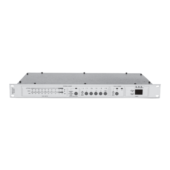
SDC100 6 External Description This chapter describes the elements of the front and rear panels of the SDC100. 6.1 Front Panel figure 6.1 [1] LEVEL METER “Left” and “Right” channels LED bar meters [2] METER SELECTOR Selector for meter (SCA/MPX or LEFT/RIGHT) -
Page 16: Rear Panel
SDC100 6.2 Rear Panel figure 6.2 [1] VOLTAGE CHANGER & Fuse block and line voltage selector. Use a small screwdriver to A.C. LINE FUSE change the fuse or line voltage. Rotate the block and position it for the desired voltage. -
Page 17: Connectors Description
6.3.1 RS 232 (only with RDS card) Tipo: DB9 female TX_D RX_D +12V Note: Normally, the SDC100 is configured as DCE (Data Communication Equipment) for serial communication. 6.3.2 Telemetry (only with RDS card) Type: DB9 female Reserved for future use... - Page 18 SDC100 This page was intentionally left blank 14 / 42 Rev. 3.0 - 09/10/01 User Manual...
-
Page 19: Technical Specifications
SDC100 7. Technical Specifications 7.1 Mechanical Specifications Panel size 483 mm (19”) x 44 mm (1.7”) (1 HE) Depth 242 mm (9.5”) Weight 4 Kg -10 °C ÷ +50 °C Temperature range 7.2 Electrical Specifications General A.C. SUPPLY 100-130 V, 50-60 Hz 198-250 V, 50-60 Hz D.C. - Page 20 SDC100 Separation (50 Ohm output load) 45dB from 30Hz to 400Hz 55dB from 400Hz to 5KHz 65dB from 5KHz to 10KHz 60dB from 10KHz to 15KHz Separation (600 Ohm output load) 50dB from 30Hz to 400Hz 60dB from 400Hz to 10KHz...
-
Page 21: Identification And Access To The Modules
8. Identification and Access to the Modules 8.1 Modules Identification Figure 8.1 shows the upper view of the internal of the coder. SDC100 is composed of different modules wired between them with connectors, allowing for easy servicing or module substitution. -
Page 22: Theory Of Operation
SDC100 8.2 Theory of Operation The figure shows the block diagrams of SDC100. The blocks are described in the following chapter: figure 8.2 18 / 42 Rev. 3.0 - 09/10/01 User Manual... -
Page 23: Mother Board
SDC100 8.3 Mother Board This card receives input signals (LEFT, RIGHT, RDS and SCA), for example from a audio mixer or a satellite receiver. These signals are normalized (amplified or attenuated) for the nominal levels, filtered (15KHz filters are included for the L and R channels) and pre-emphasized. -
Page 24: Power Supply Card
The stereo coder card is fixed on the main card and is subdivived in two sections: filtering and coding. This card, that is the most important card of the SDC100, provides to elaborate the signals coming from the main card and to transform then in stereo signal. - Page 25 SDC100 To automatically change over from a station which doesn’t transmit traffic news. The R.D.S. is proper for the transmission of information in mono/stereo programs of VHF/MF (87.5-108 Mhz). It satisfies the requested requirements to the transmission of supplementary data on radio programs: 1) Compatibility with the current mono/stereo transmissions;...
- Page 26 SDC100 This page was intentionally left blank 22 / 42 Rev. 3.0 - 09/10/01 User Manual...
-
Page 27: Software Description
9. Software Description 9.1 Software Installation (only with R.D.S. option) The supplied software (the same for all the devices R.D.S. of the R.V.R. Elettronica S.P.A.) has been planned in wise to simplify the use also by unpractised user; every performance is complete with a different available options list in order to reduce the difficult on setting. - Page 28 SDC100 Finger A: or B: (it depends from the disk drive type); Entry in the program directory on operating as follows: a) finger CD ENGLISH <INVIO> (program in italian language); b) finger RDS <INVIO> (to start the management program); On the screen you can see the followings presentation window:...
- Page 29 SDC100 N.B. In the up-link sat encoders, before the chief menu, select the place (or the encoder) you desire to connect to. A) MAIN MENU The main menu allows the following functions: Identification code SET Transmissiona mode SET P.I.N. SET...
- Page 30 SDC100 B) IDENTIFICATION CODE SETTING It’s used to set or change the identification code of a broadcaster (PROGRAM IDENTIFICATION CODE - PI) which has to be univocal into the broadcaster covering area. It’s depends from the country of the braodcaster and from the same broadcaster covering areas.
- Page 31 SDC100 For the planning it’s necessary to select the sended programmes type, in the TRANSMISSION CLASS window (ex. command ENTER on VARIOUS or NOTICES) and to select the transmission type used in the TRANSMISSION TYPE window (ex. command ENTER on STEREO).
- Page 32 SDC100 pressing the ABORT screen-command. The "P.I.N. SET" shows as follows: E) ALTERNATIVE FREQUENCIES MANAGEMENT - AF - It’s used to set or change the broadcaster sinthony frequencies lists in its diffusion areas. The menu shows as follows: 28 / 42 Rev.
- Page 33 SDC100 For the alternative frequencies transmission, the program uses two methods: A (default selectioned) and B. The two methods use the following size: A METHOD: every station send a nearly frequencies list, after the contained frequencies number (max. 25); B METHOD: every station send a frequencies list for every transmitters which it gets.
- Page 34 SDC100 On selecting the voice "MESSAGE MANAGEMENT" from the chief menu, it appears a submenu: the user has to choose which messages he wants to modify (or to simply visualize); the new menu shows as follows: At this point, the user selects one of the 8 messages (ex. message number 1) and the current message contain appears.
- Page 35 SDC100 If the user desires to modify the text, than press ENTER on the screen command MODIFY or press RETURN on the screen command EXIT. On selecting the window "MODIFY", the new menu appears, which are listed the selectable message types in; the new menu is the following: The possible type are four: Message with Date and Time;...
- Page 36 SDC100 In case of "MESSAGE with DATE and TIME", the message will contain as first 2 words, of the 16 ones, the date and the hour. In case of "MESSAGE with DATE", the message will contain as first word, of the 16 ones, the data.
- Page 37 SDC100 To set/defuse a message it’s necessary to press the command SPACE on the keyboard when the cursor is connected with the message. The active messages are where appears a "X". To change place from the column ACTIVATION to the HOUR one, it’s necessary to press the command TAB.
- Page 38 SDC100 To ability the service "Radio Text" it’s necessary to place the cursor on the window "RTEXT ON/OFF" and to press the spacebar; if a "X" appears, the procedure is right. In order to take place into the text from a word to another one, it’s sufficient to use the command TAB;...
- Page 39 SDC100 At this point, the user selects one of the 16 items (ex. Network N. 1) and the new menu is the follows: In this menu the system asks the information about Network Program Identification. To plan, it’s necessary to select the country in the window COUNTRY SELECT (ex.
- Page 40 SDC100 place on screen-command "CONTINUE" and press ENTER; at this point a new menu appears as follows: In this menu it’s possible realize the following settings: Program types sended; Program-item number (P.I.N.); Program service (PS), at most of 8 characters;...
- Page 41 SDC100 In this menu the user could set the syntony frequencies list of the broadcaster in its diffusion areas. Also in this case, as in the "Alternative Frequencies Management" one, the program is provided with two methods for the management of the frequencies list, the A, in default setted, and the B one, indicated for very long frequencies lists.
- Page 42 SDC100 The setted data within this moment are revised on the encoder only on pressing <ENTER> when appears the screen command UPDATE; they are neglected on pressing the screen command EXIT. L) TRANSPARENT CHANNEL MANAGEMENT - TDC - This option is used for the transmission of any type of data.
- Page 43 SDC100 The text could be composed at most of 8 words, each of at most 8 characters; the new menu is the following: To ability the service "IN House Application", it’s necessary to place the cursor on the window "HOUSE ON/OFF" and press the spacebar; if a “X” appears, the procedure is right.
- Page 44 SDC100 The TRDS4001/SAT Encoder version, in the chief menu, is provided with a further option, as follows: O) STATION SELECTION The RDS SAT version codifier provides the messages planning with a directely connected Pc and with a remote connection of the PC to the UP-LINK transmitter.
- Page 45 SDC100 This option allows to select 1,2,..N, all the encoders (identified by the station where they are placed in) to send the message to; if no encoder is selected, none of the other voices into the chief menu are setable.
- Page 46 SDC100 This page was intentionally left blank 42 / 42 Rev. 3.0 - 09/10/01 User Manual...
-
Page 47: Appendix
Questa parte del manuale contiene i dettagli tecnici riguardanti la costruzione delle singole schede componenti il SDC100. L’appendice è composta dalle seguenti sezioni: This part of the manual contains the technical details about the different boards of the SDC100. - Page 48 SDC100 Pagina lasciata intenzionalmente in bianco This page intentionally left blank 2 / 2 1.2 - 18/09/02 User Manual Technical Appendix...
- Page 49 SDC100 Technical Appendix Rev. 1.0 - 09/10/01 Wiring Diagram - 1 / 2...
- Page 50 SDC100 Pagina lasciata intenzionalmente in bianco This page was intentionally left blank 2 / 2 - Wiring Diagram Rev. 1.0 - 09/10/01 Technical Appendix...
- Page 51 SDC100 Technical Appendix Rev. 1.1 - 09/10/01 CSSWPSUP003 - 1 / 4...
- Page 52 SDC100 2 / 4 - CSSWPSUP003 Rev. 1.1 - 09/10/01 Technical Appendix...
- Page 53 SDC100 CSSDC100PA02 Bill Of Materials Page1 ItemQuantity Reference Part ____________________________________________________________________________________________________ CM100PF CD1KPF CM10KPF 1/25 C5,C20 1000/35 C6,C23 100/35 C7,C8,C16,C19,C21 CM.1uF C9,C10,C11,C12,C13,C14 220/25 CP10KP-5% C17,C18 CD560PF .1uF D1,D4,D5,D7 11DQ06 1N5402 1N4004 KBL04 1.5AT JP1,JP2 KB2/KS2 JP3,JP4 KB4/KS4 L1,L2,L3,L4,L5 VK200 BUK455-100A 220K...
- Page 54 SDC100 Pagina lasciata intenzionalmente in bianco This page was intentionally left blank 4 / 4 - CSSWPSUP003 Rev. 1.1 - 09/10/01 Technical Appendix...
- Page 55 SDC100 Technical Appendix Rev. 1.0 - 09/10/01 CSSDC100PA02 - 1 / 4...
- Page 56 SDC100 2 / 4 - CSSDC100PA02 Rev. 1.0 - 09/10/01 Technical Appendix...
- Page 57 SDC100 SLSDC100PA02 Bill of Materials Item Reference Part Description RVRCode __________________________________________________________________________ Circuito stampato CSSDC100PA02 0.1uF Cond. ceramico p. 5mm CKM104BK600P 10uF Cond. el. ver. 16V p. 2.5mm CEA106BM160 LM3915 CI lineare CILLM3915 LM3915 CI lineare CILLM3915 0.1uF Cond. ceramico p. 5mm CKM104BK600P 0.1uF...
- Page 58 SDC100 LED-G Led Verde Quadro 5x5 mm LEDVEQ5 LED-G Led Verde Quadro 5x5 mm LEDVEQ5 LED-G Led Verde Quadro 5x5 mm LEDVEQ5 LED-G Led Verde Quadro 5x5 mm LEDVEQ5 LED-G Led Verde Quadro 5x5 mm LEDVEQ5 LED-G Led Verde Quadro 5x5 mm...
- Page 59 SDC100 Technical Appendix Rev. 1.0 - 09/10/01 SLSDC100MB01 - 1 / 8...
- Page 60 SDC100 2 / 8 - SLSDC100MB01 Rev. 1.0 - 09/10/01 Technical Appendix...
- Page 61 SDC100 SLSDC100MB01 Bill of Materials Item Reference Part Description RVRCode __________________________________________________________________________ Circuito stampato CSSDC100MB01 Res. 1/4 W 5% RSC1/4JH0100 10K0 Res. 1/4 W 1% RSM1/4FK0010 10K0 Res. 1/4 W 1% RSM1/4FK0010 10K0 Res. 1/4 W 1% RSM1/4FK0010 11K0 Res. 1/4 W 1%...
- Page 62 SDC100 2.2uF Cond. el. ver. 16V p. 2.5mm CEA225BM160 27pF Cond. ceramico p. 5mm CKM270BK600C 27pF Cond. ceramico p. 5mm CKM270BK600C 27pF Cond. ceramico p. 5mm CKM270BK600C 27pF Cond. ceramico p. 5mm CKM270BK600C 27pF Cond. ceramico p. 5mm CKM270BK600C 27pF Cond.
- Page 63 SDC100 10K0 Res. 1/4 W 1% RSM1/4FK0010 Res. 1/4 W 5% RSC1/4JH0220 Res. 1/4 W 5% RSC1/4JH0220 51H0 Res. 1/4 W 1% RSM1/4FH0051 27pF Cond. ceramico p. 5mm CKM270BK600C 10K0 Res. 1/4 W 1% RSM1/4FK0010 1N4148 Diodo silicio DIS1N4148 10uF Cond.
- Page 64 SDC100 10uF Cond. el. ver. 16V p. 2.5mm CEA106BM160 0.1uF Cond. ceramico p. 5mm CKM104BK600P 10uF Cond. el. ver. 16V p. 2.5mm CEA106BM160 10uF Cond. el. ver. 16V p. 2.5mm CEA106BM160 10uF Cond. el. ver. 16V p. 2.5mm CEA106BM160 10uF Cond.
- Page 65 SDC100 10K0 Res. 1/4 W 1% RSM1/4FK0010 10K0 Res. 1/4 W 1% RSM1/4FK0010 10K0 Res. 1/4 W 1% RSM1/4FK0010 10K0 Res. 1/4 W 1% RSM1/4FK0010 Res. 1/4 W 1% RSM1/4FK0001 Res. 1/4 W 1% RSM1/4FK0001 R105 10K0 Res. 1/4 W 1%...
- Page 66 SDC100 2.2uH Impedenza IMP02U2A 2.2uH Impedenza IMP02U2A 2.2uH Impedenza IMP02U2A 2.2uH Impedenza IMP02U2A 2.2uH Impedenza IMP02U2A 2.2uH Impedenza IMP02U2A 2.2uH Impedenza IMP02U2A 2.2uH Impedenza IMP02U2A 2.2uH Impedenza IMP02U2A 2.2uH Impedenza IMP02U2A Res. IMP02U2A 2.2uH Impedenza IMP02U2A Res. Res. 1/4 W 1% RSM1/4FM0001 Res.
- Page 67 SDC100 Technical Appendix Rev. 1.1 - 18/09/02 CSSTCOD03 - 1 / 6...
- Page 68 SDC100 2 / 6 - CSSTCOD03 Rev. 1.1 - 18/09/02 Technical Appendix...
- Page 69 SDC100 SLPTCODSTE03 Bill Of Materials Page1 ItemQuantity Reference Part ____________________________________________________________________________________________________ CLP1 CLIPPER CLP2 CLIPPER COD1 CODER PERRY 220uF 220uF 0.1uF 0.1uF 0.1uF 0.1uF 0.1uF 0.1uF 0.1uF 0.1uF 0.1uF 0.1uF 0.1uF 0.1uF 0.1uF 0.1uF 0.1uF 0.1uF 0.1uF 0.1uF 0.1uF 0.1uF 0.1uF 0.1uF...
- Page 70 SDC100 FIX1 FIX35 FIX2 FIX35 FIX3 FIX35 FIX4 FIX35 FILPERRY STM26D STM16D CN16PD BC327 TMV1K TMV1K TMV1K TMV10K TMV10K TMV50K TMV50K 475K 100K 4 / 6 - CSSTCOD03 Rev. 1.1 - 18/09/02 Technical Appendix...
- Page 71 SDC100 100K 180K 4094 7808 TL072 TL072 TL072 TL072 TL072 4066 4053 4053 LM393 CA3096 Technical Appendix Rev. 1.1 - 18/09/02 CSSTCOD03 - 5 / 6...
- Page 72 SDC100 Pagina lasciata intenzionalmente in bianco This page intentionally left blank 6 / 6 - CSSTCOD03 Rev. 1.1 - 18/09/02 Technical Appendix...
- Page 73 SDC100 Technical Appendix Rev. 1.0 - 09/10/01 SLPTCODSTE02 - 1 / 4...
- Page 74 SDC100 2 / 4 - SLPTCODSTE02 Rev. 1.0 - 09/10/01 Technical Appendix...
- Page 75 SDC100 SLPTCODSTE02 Bill Of Materials Page1 Item Quantity Reference Part _______________________________________________________________________ COD1 CODERPERRY CX2,CX1 220uF C1,C3,C39,C40,C41,C42 47pF CV40pF CV20pF C5,C8,C9,C10,C14,C17,C18, 0.1uF C19,C20,C22,C28,C29,C30, C31,C32,C33,C34,C35 C6,C7,C13,C15,C16,C35, 10uF C11,C23 2n2P C12,C25 100pF C24,C26 1nFP D3,C27 DX1,DX2 BAT83 LED-R3 1N4148 FIX1,FIX2,FIX3,FIX4 FIX35 FILPERRY STM26D...
- Page 76 SDC100 U5,U6 4053 7908 7808 LM393 4 / 4 - SLPTCODSTE02 Rev. 1.0 - 09/10/01 Technical Appendix...
- Page 77 SDC100 Technical Appendix Rev. 1.1 - 09/10/01 CSSDCRDS003 - 1 / 8...
- Page 78 SDC100 2 / 8 - CSSDCRDS003 Rev. 1.1 - 09/10/01 Technical Appendix...
- Page 79 SDC100 Technical Appendix Rev. 1.1 - 09/10/01 CSSDCRDS003 - 3 / 8...
- Page 80 SDC100 4 / 8 - CSSDCRDS003 Rev. 1.1 - 09/10/01 Technical Appendix...
- Page 81 SDC100 Technical Appendix Rev. 1.1 - 09/10/01 CSSDCRDS003 - 5 / 8...
- Page 82 SDC100 SLSDC_RDS002 Bill Of Materials Page Item Quantity Reference Part _____________________________________________________ CN1,CN2 DB9FSO STF90D BNC_IS90 C1,C3,C4,C5,C6,C8,C10, 0.1uF C12,C15,C17,C19,C20,C21, C22,C25,C26,C27,C32,C33, C35,C36,C37,C38,C39,C41, C42,C44,C46,C47,C51,C52, C53,C68,C69,C72 47uF C7,C9,C11,C13,C14,C16, 10uF C24,C40,C43,C71,C73 100pF C23,C30,C34,C66 10nF D1,U2,D2,R4,D5,R6,R25, C29,R75 C45,C48,C49,C50,C67 47nF C55,C54 27pF 470nF C57,C58,C59,C60,C61,C62, 1.5nF 330pF 560pF...
- Page 83 SDC100 390H0 R16,R60 R19,R36 47K0 475K0 R21,R29,R57 100K0 4K99 R27,R65 18K2 R32,R34 3K90 R37,R35 80K6 6K80 R43,R72,R76,R77 2K20 R46,R47,R71 100H0 R48,R70 332H0 R51,R52,R74 22H0 R53,R68 4K75 20K0 14K7 4K99 11K0 47H0 8K25 TP1,TP2,TP3 BQ3287 LM2940CT5.0 7808 7908 43256 7407SMD 74HC04SMD...
- Page 84 SDC100 Pagina lasciata intenzionalmente in bianco This page was intentionally left blank 8 / 8 - CSSDCRDS003 Rev. 1.1 - 09/10/01 Technical Appendix...
- Page 85 SDC100 Technical Appendix Rev. 1.0 - 09/10/01 SLPTCPU55202 - 1 / 4...
- Page 86 SDC100 2 / 4 - SLPTCPU55202 Rev. 1.0 - 09/10/01 Technical Appendix...
- Page 87 SDC100 SLPTCPU55202 Bill Of Materials Page1 ItemQuantity Reference Part _____________________________________________________________________________________________________ STM90D C1,C2 22pF C8,C15,C16,C17,C18,C19, 0.1uF C10,C11,C20,C25 10uF 10nF D1,D2,D3,D4,D5,D6,D7,D8, LED-R3 FIX1,FIX2,FIX3,FIX4 FIX35 STM18D STM08D U11,J3 Q14M74 RR2,RR1 R1,R2,R6 80C552 74HC138 27C512 74HC573 74HC541 MAX232 Technical Appendix Rev. 1.0 - 09/10/01...
- Page 88 SDC100 Pagina lasciata intenzionalmente in bianco This page was intentionally left blank 4 / 4 - SLPTCPU55202 Rev. 1.0 - 09/10/01 Technical Appendix...
Need help?
Do you have a question about the SDC100 and is the answer not in the manual?
Questions and answers