Table of Contents
Advertisement
Quick Links
Advertisement
Table of Contents

Subscribe to Our Youtube Channel
Related Manuals for R.V.R. Elettronica TEX300LCD


Summary of Contents for R.V.R. Elettronica TEX300LCD
- Page 1 TEX300LCD User Manual Volume 1 Manufactured by Italy...
- Page 2 Document History Date Version Reason Editor 24/02/2006 First Edition J. H. Berti TEX300LCD - User Manual Version 1.0 © Copyright 2006 R.V.R. Elettronica SpA Via del Fonditore 2/2c - 40138 - Bologna (Italia) Telephone: +39 051 6010506 Fax: +39 051 6011104 Email: info@rvr.it...
-
Page 3: Table Of Contents
TEX300LCD Table of Contents Preliminary Instructions Warranty First Aid Treatment of electrical shocks Treatment of electrical Burns Removal from the packing General Description Quick guide for installation and use Preparation Settings and calibration Software Optional Functions External Description Front Panel... - Page 4 TEX300LCD This page was intentionally left blank Rev. 1.0 - 24/02/06 User Manual...
-
Page 5: Preliminary Instructions
2. Warranty R.V.R. Elettronica SpA Via del Fonditore, 2/2c 40138 BOLOGNA Any product of R.V.R. Elettronica is covered by a 24 ITALY (twenty-four) month warranty. Tel. +39 051 6010506 For components like tubes for power amplifiers, the 3. First Aid original manufacturer’s warranty applies. -
Page 6: Treatment Of Electrical Burns
TEX300LCD Treatment of electrical Burns • clear out mouth if necessary and observe for breathing 3.2.1 Extensive burned and broken skin • if not breathing, begin artificial breathing • Cover area with clean sheet or cloth. (Figura 2): tilt head, pinch nostrils, make airtight seal, four quick full breaths. -
Page 7: Removal From The Packing
10 KHz, with an RF output power adjustable up to a maximum of 300W into a 50 Ohm standard load. The TEX300LCD is designed to being contained into a 19” rack box of 2HE. This exciter contains a low-pass filter that reduces the harmonic emissions to below the limits allowed by international regulations (CCIR, FCC or ETSI), and can therefore be used as a transmitter connected directly to the antenna. - Page 8 TEX300LCD The microprocessor system includes an LCD display and push-button panel for interaction with the user, and implements the following functions: • Setting the output power • Setting the operating frequency • Activation and deactivation of power delivery • Measurement and display of the working parameters of the exciter • Communications with outside devices...
-
Page 9: Quick Guide For Installation And Use
The fuse to be used is this type: Mains Fuse: 8 A-T 5X20 Check that the TEX300LCD switches are in the “OFF” position. The exciter has two switches: one is incorporated in the VDE base for the mains power supply, whereas the second one is on the front panel and inhibits the switching power supply of the machine. -
Page 10: Settings And Calibration
Activate the RF power output from the “Fnc” menu (chap. 5.4.1). 5.3 Settings and calibration The only adjustments to have made manually on the TEX300LCD are those relating to the audio operation levels and modes. A trimmer for each one of the exciter’s inputs is on the rear panel of the device. -
Page 11: Software
TEX300LCD The positions of the DIP switches that are used to select the available options are indicated on the printing. • Preemphasis (Figure 6.2 - [26]): 50 µs 75 µs • L and R input impedance (type XLR) (Figure 6.2 - [12]): Switch 1: R XLR input impedance, ON = 600 Ω, OFF = 10 kΩ... - Page 12 TEX300LCD The vertical bars under “Mod” indicate the progress of the modulation in real time; the hatched bar signals the maximum nominal modulation level at 75 kHz (100%). To change the set power level, select the line relating to the power with the...
- Page 13 TEX300LCD Menu 2 Menu 2 Menu 1 Menu 1 Predefined menu Power Adjustment Menu Menu 3 Menu 3 Selection Menu Menu 4 Menu 4 Operation Menu Menu 5 Menu 5 Power Menu Menu 6 Menu 6 Power Amplifier Menu Menu 7...
- Page 14 TEX300LCD 5.4.1 Operation Menu (Fnc) From this menu the user can enable or disable the exciter power supply, set the deviation display modality and set up the percentage of Forward (PgD) or Reflected Power Good (PgR). To operate on one of this voices, select the relative line by the buttons, then press and keep pressed the ENTER button until the command doesn’t come...
- Page 15 TEX300LCD 5.4.2 Power Menu (Pwr) This screen shows the user the measures relating to the exciter’s RF power output: Menu 5 Visualization of the Forward Power (Fwd). V isualization of the Reflected Power (Rfl). The values shown are “readings”, and therefore cannot be modified (note the empty triangle). To modify the power setting, use the predefined menu as described...
- Page 16 TEX300LCD After having set a new frequency value, press the ENTER button to confirm the choice. The exciter will release from the current frequency (the LOCK LED turns off) and it will latch onto the new operating frequency (LOCK turns back on). Instead, if you press ESC or let the timeout go by, the frequency will remain set at the previous value.
-
Page 17: Optional Functions
By factory the amplitude of the frequency shifts is +10 KHz and the time lag of the code repeat is 60 minutes (for values different from these parameters, please contact R.V.R. Elettronica SpA). As regards the Radio code, it can be set by the user following the indications described in chapter 5.5.1.1. - Page 18 TEX300LCD 5.5.1.1 Code Modification In every moment the user is able to make changes to the Radio code transmitted in FSK. In order to make the operation is necessaryto have: • 1 RS232 male - female cable; • Hyper Terminal Interface (verify that it has been installed together to the own ®...
- Page 19 TEX300LCD Configuration of the telemetry DB15F connector (Remote): Pin Standard Function UP/DOWN Power Function On cmd Up cmd Enables RF power supply Increases RFthe Power supply Off cmd Down cmd Disables RF power supply Reduces RFthe Power supply User Manual Rev. 1.0 - 24/02/06 15 / 26...
-
Page 20: External Description
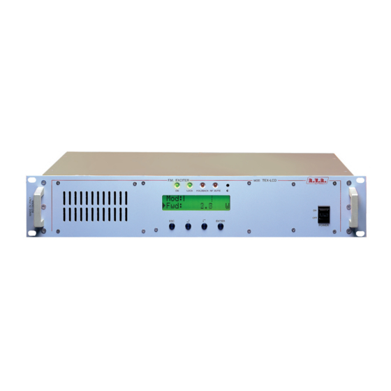
TEX300LCD 6. External Description This chapter reports the elements of the front and rear panels of the with a brief description of each of them. 6.1 Front Panel Figure 6.1 [1] AIR FLOW Grid for the passage of the air flow of the forced ventilation [2] ON Green LED, lit when the exciter is working... -
Page 21: Rear Panel
TEX300LCD 6.2 Rear Panel figure 6.2 [1] PLUG Mains supply plug, 90 - 260V 50-60 Hz. [2] FAN Fan for the forced ventilation of the exciter. [3] R.F. OUTPUT RF output connector, N-type, 50Ω. [4] 24VDC IN - External 24Vdc supply input. Negative (black). -
Page 22: Connectors Description
TEX300LCD 6.3 Connectors description 6.3.1 RS 232 Type: DB9 female TX_D RX_D Internally connected with 6 Internally connected with 4 Internally connected with 8 Internally connected with 7 6.3.2 Remote Type: DB15 female Pin Name Type Meaning Interlock By passes power if closed at GND Ext AGC FWD Ext. -
Page 23: Technical Specifications
TEX300LCD 7. Technical Specifications 7.1 Mechanical characteristics Panel Size 483 mm (19”) x 88 mm (2 HE) Depth 355 mm Weight approx. 6,5 Kg -10 °C ÷ 50 °C, without condensing Working Temperature 7.2 Electrical characteristics General Output RF power 0-300 W adjustable with continuity 87.5MHz ÷... - Page 24 TEX300LCD Outputs RF Out N-type female connector Output Impedance 50 Ohm RF Test BNC connector 50 Ohm Output level level -60dB compared to RF output 19kHz Out BNC female connector for isofrequency and RDS synchronization Output Impedance >5 kOhm 19 KHz pilot tone...
-
Page 25: Spare Parts
TEX300LCD ± 0.5dB, 30Hz ÷ 15Khz Amplitude/frequency response < 0.05%, THD+N 30Hz ÷ 15Khz Total Harmonic Distortion (THD) ≤ 0.03%, measured with 1KHz and 1.3KHz Intermodulation distortion tones, 1:1 ratio, at 75KHz Transient intermodulation distortion < 0.1% (typical 0.05%), measured with 3.18KHz square wave and 15KHz sinusoidal... -
Page 26: Working Principles
8. Working Principles 8.1 Power Supply The TEX300LCD power supply unit is a switching-type unit whose +50 V main output powers the machine’s RF amplifier. The power supply also features stabilizers for generating continuous +5 V and +18 V voltages for supplying the other equipment circuits. -
Page 27: Power Amplifier
TEX300LCD • Modulating signal measurement 8.3.2 PLL/VCO section This board section generates the modulated radiofrequency signal. It is based on a PLL scheme that uses an integrated MB15E06 type. 8.3.3 Driver section Before passing to the final power amplifier, the RF signal is preamplified in this section by an ERA3 transistor. When the exciter is placed on stand-by, the driver is by-passed. -
Page 28: Control Board
TEX300LCD 8.5 Control Board The main function of this board is to check and correct the MOSFET polarization voltage of the RF amplifier section. It also provides the measurement of the absorbed current and contains a circuit for signaling power supply unit faults. If no alarms are present, the voltage is adjusted only depending on the set output power, with a feedback mechanism based on the reading of the power really delivered (AGC). -
Page 29: Identification And Access To The Modules
TEX300LCD 9. Identification and Access to the Modules 9.1 Identification of the Modules The TEX300LCD is made up of various modules linked to each other through connectors so as to make maintenance and any required module replacement easier. 9.1.1 Upper view The figure below shows the equipment upper view with the various components pointed out. figure 8.1 [1] Main & Stereo Coder Card (SLMBDTEXLC05 & SLCTC30V03) - Page 30 TEX300LCD This page was intentionally left blank 26 / 26 Rev. 1.0 - 24/02/06 User Manual...
Need help?
Do you have a question about the TEX300LCD and is the answer not in the manual?
Questions and answers