
Related Manuals for R.V.R. Elettronica RXRL-NV


Summary of Contents for R.V.R. Elettronica RXRL-NV
- Page 1 RXRL-NV T E C H N I C A L A N D M A I N T E N A N C E M A N U A L M A N U A L E T E C N I C O E D I M A N U T E N Z I O N E...
- Page 2 RXRL-NV Technical and Maintenance Manual RXRL-NV STUDIO TRANSMITTER LINK 200/ 1100MHz Technical and Maintenance Manual Manuale Tecnico e di Manutenzione English Pag. 3 Italiano Pag. 49 R.V.R. Elettronica S.r.l. (Bo) Pag. 2...
- Page 3 RXRL-NV Technical and Maintenance Manual INDEX Preliminary Instructions and Warranty Information Pag. 5 Safety Regulations Pag. 7 SECTION 1 General Description Pag. 10 Technical Specifications (Table A) Pag. 12 Dimensional & Environmental Specifications (Table B) Pag. 13 CHAPTER 2 Electrical Description Pag.
- Page 4 RXRL-NV Technical and Maintenance Manual Card Connections Pag. 96 Power Supply Pag. 97 Muting Card Pag. 102 C.P.U. Pag. 106 Modmeter Card Pag. 116 Anameter Card Pag. 121 P.L.L. Card Pag. 129 V.C.O. Card Pag. 141 I.F. 70MHz Card Pag. 146 Front End &...
- Page 5 RXRL-NV Technical and Maintenance Manual PRELIMINARY INSTRUCTIONS AND WARRANTY INFORMATION WARNING: This equipment is a "CLASS A" equipment. In a residential place this equipment can cause hash. In this case can be requested to user to take the necessary measures.
- Page 6 RXRL-NV Technical and Maintenance Manual The warranty for a period of 12 months is referred to any R.V.R. product, while for products as transistors, Mos-Fet and tubes of the final stages is applied the manufacture's warranty of these devices. To claim your rights under this warranty: Contact the dealer or distributor where you purchased the unit.
- Page 7 R.V.R. ELETTRONICA S.r.l. shall not be responsible for injury or damage resulting from improper procedures or from the use of improperly trained or inexperienced personnel performing such tasks.
- Page 8 RXRL-NV Technical and Maintenance Manual TreatmentofelectricalShock 1) If victim is not responsive follow the A-B-C's of basic life support. PLACE VICTIM FLAT ON HIS BACK ON A HARD SURFACE A A I R W A Y BBREATHING IF UNCONSCIOUS, IF NOT BREATHING,...
- Page 9 RXRL-NV Technical and Maintenance Manual FIRST-AID Personnelengagedintheinstallation,operation,maintenanceor servicingofthisequipmentareurgedtobecomefamiliarwithfirst-aid theoryandpractices.Thefollowinginformationisnotintendedtobe acompletefirst-aidprocedure,itisbriefandisonlytobeusedas areference.Itisthedutyofallpersonnelusingtheequipmenttobe preparedtogiveadequateEmergencyFirstAidandtherebyprevent avoidablelossoflife. Treatment of electrical Burns 1) Extensive burned and broken skin. a. Cover area with clean sheet or cloth. (Cleansed available cloth article). b. Do not break blisters, remove tissue, remove adhered particles clothing, or apply any salve or ointment.
- Page 10 SECTION 1 GENERAL DESCRIPTION 1.1 MECHANICAL DESCRIPTION The RXRL-NV is housed in a 2U, 19" rack-mounting chassis comprising a number of interconnected modules mounted internally on the base of the unit. This allows easy removal and replacement of each module.
- Page 11 RXRL-NV Technical and Maintenance Manual 1.5 SPECIFICATIONS Please refer to Table A for the electrical specifications and Table B for the mechanical specifications. R.V.R. Elettronica S.r.l. (Bo) Pag. 11...
- Page 12 RXRL-NV Technical and Maintenance Manual TABLE A ELECRICAL SPECIFICATIONS A.C. Power 100,120,220 and 240 V ±10% 50-60 Hz, single phase 22W 24 Vdc optional Cooling Forced ventilation Operating frequency from 200 to 1100 MHz in Sub-Bands of 25MHz Sensitivity MPX: 1.00mV or less for 60dB SNR Mono: 100µV or less for 65dB SNR...
- Page 13 RXRL-NV Technical and Maintenance Manual TABLE B D I M E N S I O N A L A N D E N V I R O M E N T A L S P E C I F I C A T I O N S Chassis dimensions 82 mm (3.22") H...
- Page 14 RXRL-NV Technical and Maintenance Manual SECTION 2 ELECTRICAL DESCRIPTION 2.1 INTRODUCTION This section describes, in detail, the operating theory of the RXRL-NV. To aid understanding, the unit has been subdivided into blocks, each of which is fully described below. A block diagram is shown in fig. 3.
- Page 15 RXRL-NV Technical and Maintenance Manual for the stereo signal. A switch allows the gain of the measuring circuit to be set to 10% or 100% for a more precise reading of low-level deviation (eg. SCA, RDS, pilot tones). Another switch sets the display mode to bar-graph or peak mode.
- Page 16 RXRL-NV Technical and Maintenance Manual 2.8 AUDIO PROCESS CARD This card is mounted in the rear of the metal container situated in the center of the unit (11 Photo1). The Audio Process card processes the various audio signals such as MONO, MPX, SCA and RDS coming from the 70MHz IF card.
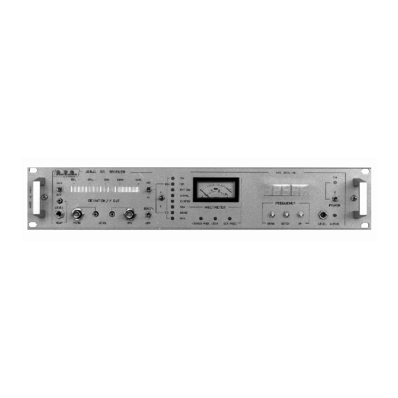
- Page 17 RXRL-NV Technical and Maintenance Manual FRONT PANEL VIEW DESCRIPTION (Fig.1) LEVEL HEAR Hear level trimmer HEAR Hear jack MONO Mono output connector, BNC type MONO LEVEL TRIMMER Mono Level Trimmer STEREO LEVEL TRIMMER Stereo Level Trimmer Stereo output connector, BNC type...
- Page 18 RXRL-NV Technical and Maintenance Manual SCA PRES. SCA signal led indicator (only with SCA internal decoder included) DOWN Control frequency display. Any momentary pushes causes the digit to go down 10KHz a time ENTER Enters the frequency on the display into microprocessor and memory.
- Page 19 RXRL-NV Technical and Maintenance Manual METER Analog meter used to monitor the parameters of the receiver such as: +15V EXT 24V SIGNAL CENTER MONO FREQUENCY DISPLAY Frequency indicator ON/OFF Power Switch Led POWER ON/OFF Power Switch R.V.R. Elettronica S.r.l. (Bo)
- Page 20 RXRL-NV Technical and Maintenance Manual FIG.1 R.V.R. Elettronica S.r.l. (Bo) Pag. 20...
- Page 21 RXRL-NV Technical and Maintenance Manual REAR PANEL VIEW DESCRIPTION (Fig.2) PLUG A.C. power plug FUSE BLOCK Fuse Block & Voltage. Use a small screwdriver to change fuse or voltage setting. Turn block and place desired operating voltage next to arrow...
- Page 22 RXRL-NV Technical and Maintenance Manual Cooling fan TEST POINT 10.7MHz Test point connector 10.7MHz VOLTAGE REGULATOR 1 Voltage regulator for +5V VOLTAGE REGULATOR 2 Voltage regulator for +15V R.F. INPUT 50 Ohm, "N" Connector R.V.R. Elettronica S.r.l. (Bo) Pag. 22...
- Page 23 RXRL-NV Technical and Maintenance Manual FIG.2 R.V.R. Elettronica S.r.l. (Bo) Pag. 23...
- Page 24 RXRL-NV Technical and Maintenance Manual TOP VIEW DESCRIPTION (PHOTO1) ....Supply Socket ....Power Supply ....Transformer ....C.P.U....Anameter Board ....Modulation Meter & Mono/Mpx Output Board ....IF 70MHz Card ....P.L.L. Board ....Front-End & Mixer ....
- Page 25 RXRL-NV Technical and Maintenance Manual PHOTO 1 R.V.R. Elettronica S.r.l. (Bo) Pag. 25...
- Page 26 RXRL-NV Technical and Maintenance Manual FIG.3 R.V.R. Elettronica S.r.l. (Bo) Pag. 26...
- Page 27 3.3 INSTALLATION To install the RXRL-NV receiver, carry out the following procedure: This receiver is able to operate from 4 different supply voltages: 100, 120, 220 or 240Vac, at 50-60Hz.
- Page 28 RXRL-NV Technical and Maintenance Manual operating frequency to have been programmed. The green LOCK led should switch on within 30 seconds indicating that oscillator locked operating frequency displayed. The display has five digits, 3 before the decimal point representing (from left to right) hundreds of MHz, tens of MHz and MHz;...
- Page 29 RXRL-NV Technical and Maintenance Manual received signal is centered. Deviation meter check. Set the modulation display gain (20 Fig.1) to 130% f.s.d. Connect an audio analyzer to the MONO output (3 Fig.1). Check that the bar-graph diaplay (18 Fig.1) lights up to the first red led, indicating 100% deviation (equivalent to 75KHz).
- Page 30 RXRL-NV Technical and Maintenance Manual TABLE C RECOMMENDED TEST EQUIPMENT INSTRUMENT MODEL SPECIFICATION Non-Inductive Dummy Load Bird 50 Ohm P>10W Spectrum Analyzer Advantest 10KHZ-3.5GHz Mod. R4131D F.M. Modulation Meter Mod. F.A.M. Digital multimeter Mod. Metrix Bypass Wattmeter Bird 50 Ohm Mod.
- Page 31 MAINTENANCE LEVEL 1 4.2 ROUTINE MAINTENANCE The only routine maintenance required by the RXRL-NV is the periodic replacement of the cooling fan and the removal of accumulated dust. The period between such action will depend on ambient operating conditions such as temperature, air-borne dust levels and humidity.
- Page 32 RXRL-NV Technical and Maintenance Manual Undo the screws holding the CPU’s protective metal container, and remove the cards. 4.4 ANAMETER CARD REPLACEMENT Open the top cover of the unit. Undo the front panel fixing screws. Disconnect connector CN1 connecting the Anameter card to the Audio Process card.
- Page 33 RXRL-NV Technical and Maintenance Manual Remove the Power Supply with great care. 4.7 FRONT-END & MIXER REPLACEMENT Open the top cover of the unit. Disconnect connectors CN1 and CN2. Desolder the power cable coming from the PLL card. Undo the screws fixing the Front-end Mixer to the rear panel.
- Page 34 RXRL-NV Technical and Maintenance Manual Undo the nuts holding the card in place and remove the card with the great care. 4.11 70 MHz IF CARD REPLACEMENT Open the top cover of the unit. Open the cover of the metal container which protects the Audio Process card and the 70MHz IF card.
- Page 35 RXRL-NV Technical and Maintenance Manual SECTION 5 CALIBRATION PROCEDURE OF MODULES 5.1 INTRODUCTION TO ENSURE AN ACCURATE CALIBRATION OF THE RECEIVER, ALLOW THE UNIT TO REACH NORMAL OPERATING TEMPERATURE BEFORE CALIBRATION 5.2 CALIBRATION OF THE FRONT-END To carry out this procedure, configure the unit as detailed in...
- Page 36 RXRL-NV Technical and Maintenance Manual Gradually reduce the level of the injected R.F. signal continuing to adjust for the maximum 10.7 MHz IF signal level. Repeat this operation until the injected signal level is less than -47 dBm (1mV). With an R.F. input level of -47 dBm, having adjusted the compensators on the Front-end Mixer, check that the 10.7 MHz IF signal level is...
- Page 37 RXRL-NV Technical and Maintenance Manual Measure the MONO signal level output by the receiver into the audio signal analyzer. Adjust TR3 for the maximum value and TR4 for the minimum. Set the audio analyzer to a measure audio distortion percentage with a low-pass filter at 30 KHz.
- Page 38 RXRL-NV Technical and Maintenance Manual Inject a signal with the carrier at the receiver’s operating frequency and modulated with 400 Hz at ±75 KHz deviation. Adjust R8 to obtain a reading on the audio analyzer of +13 dBm for the MONO input.
- Page 39 RXRL-NV Technical and Maintenance Manual If the Stereo Decoder has an OVER RANGE indicator, adjust the stereo output level until the indicator just switches off. Inject a carrier at the receiver’s operating frequency, modulated by a 10 KHz tone with a deviation of ±75 KHz.
- Page 40 RXRL-NV Technical and Maintenance Manual Configure the unit as detailed in SETUP6. SETUP 6 Adjust trimmer R28, situated on the Audio Process card, to obtain a reading of 0 dBm. Adjust R15 so that the first red led of the bar- graph display switches on.
- Page 41 RXRL-NV Technical and Maintenance Manual Inject a carrier at the receiver’s operating frequency, modulated by a 400 Hz tone with 7,5 KHz deviation. Adjust trimmer R4, situated on the Modmeter card, so that the first red led switches on (corresponding to the 100% mark).
- Page 42 RXRL-NV Technical and Maintenance Manual SECTION 6 ALIGNMENT OF THE RADIO LINK 6.1 INTRODUCTION This chapter details the alignment procedure for the PTRL-NV transmitter and the RXRL-NV receiver. 6.2 FREQUENCY ALIGNMENT The operating frequency of the complete radio link (TX + RX) is set using a frequency meter to measure the frequency output by the transmitter and the frequency after the second conversion of the receiver.
- Page 43 RXRL-NV Technical and Maintenance Manual Switch on the tranmitter and wait until it has locked to its operating frequency and the UNLOCK light goes out. Connect through a wattmeter with sample a frequency meter and a dummy load, rated at 15W continuous, to the output situated on the rear panel of the transmitter.
- Page 44 R.F. signal into the receiver input. Using the FAM modulation analyzer, check that the S/N ratio of the RXRL-NV receiver is better than 65 dB, referred to a deviation of ±75 KHz. Connect the instruments as shown in SETUP B2 to make the STEREO measurement.
- Page 45 RXRL-NV Technical and Maintenance Manual SETUP B2 6.4 STEREO SEPARATION Stereo separation is measured using a stereo coder, a stereo demodulator. The figure is obtained from the ratio of the left and right channel outputs with only the left channel modulated, for frequencies between 30 Hz and 15 KHz.
- Page 46 RXRL-NV Technical and Maintenance Manual 6.5 CHANGING FREQUENCY There are three different procedures for changing frequency, depending on the new frequency to be selected: CASE A Should the new frequency fall within the range selectable by the CPU (and without the requirement of a change of EPROM), the following...
- Page 47 Select the SIGNAL measurement using the selector (20 Fig.1) and confirmed by the corresponding green led (8 Fig.1). Calibrate the VCO as detailed in paragraph 5.10 of the RXRL-NV manual. Calibrate the 6 compensators, situated on the two filters FIL1 and FIL2 of the Front-end Mixer, for the maximum R.F.
- Page 48 Select the SIGNAL measurement using the selector (20 Fig.1) and confirmed by the corresponding green led (8 Fig.1). Calibrate the VCO as detailed in paragraph 5.10 of the RXRL-NV manual. Calibrate the 6 compensators, situated on the two filters FIL1 and FIL2 of the Front-end Mixer, for the maximum R.F.
- Page 49 RXRL-NV Technical and Maintenance Manual INDICE Istruzioni Preliminari e Informazioni di Garanzia Pag. 51 Regole di Sicurezza Pag. 53 CAPITOLO 1 Descrizione Generale Pag. 56 Caratteristiche Tecniche (Tabella A) Pag. 58 Caratteristiche Dimensionali e Ambientali (Tabella B) Pag. 59 CAPITOLO 2 Descrizione Elettrica Pag.
- Page 50 RXRL-NV Technical and Maintenance Manual Connessione delle Schede Pag. 96 Power Supply Pag. 97 Muting Card Pag. 102 C.P.U. Pag. 106 Modmeter Card Pag. 116 Anameter Card Pag. 121 P.L.L. Card Pag. 129 V.C.O. Card Pag. 141 I.F. 70MHz Card Pag.
- Page 51 RXRL-NV Technical and Maintenance Manual ISTRUZIONI PRELIMINARI E INFORMAZIONI DI GARANZIA ATTENZIONE: Questo è apperecchio "Classe A". ambiente residenziale questo apperecchio può provocare radio disturbi. In questo caso può essere richiesto all'utillizzatore di prendere misure adeguate. Si prega di osservare le necessarie precauzioni di sicurezza quando si usa questa apparecchiatura.
- Page 52 RXRL-NV Technical and Maintenance Manual La garanzia entrerà in vigore dalla data di fattura per il periodo di garanzia di costruzione. Per reclamare i propri diritti con questa garanzia: Contattare il rivenditore o il distributore dove avete acquistato la macchina. Descrivere il problema e chiedere se è in grado di fornirvi una facile soluzione.
- Page 53 La società R.V.R. ELETTRONICA s.r.l. non sarà responsabile per lesioni o danni risultanti da procedure improprie o dall’uso di personale inesperto o non correttamente addestrato all’adempimento di tali mansioni.
- Page 54 RXRL-NV Technical and Maintenance Manual T r a t t a m e n t o d e g l i s h o c k e l e t t r i c i 1) Se la vittima ha perso conoscenza seguire i principi di primo soccorso riportati nei punti A-B-C.
- Page 55 RXRL-NV Technical and Maintenance Manual PRIMO SOCCORSO Ilpersonaleimpegnatonell’installazione,nelfunzionamento,nella manutenzioneoassistenzadiquestodispositivohalanecessitàdiavere familiaritàconlateoriaelepratichediprimosoccorso. La relazione seguente non rappresenta una guida completa delle procedure di primo soccorso, ma è solo un riassunto che deve essere usato come riferimento. E’ compito di tutto il personale che usa questo dispositivo essere pronto a prestare un adeguato soccorso e perciò...
- Page 56 Sul pannello posteriore si trovano i connettori d’ingresso rete, l’ingresso RF e l’uscita monitoria della seconda I.F. 1.2 DESCRIZIONE ELETTRICA Il RXRL-NV è un ricevitore FM Broadband ad alta fedeltà con una distorsione armonica inferiore al 0.2%. Questo ricevitore è sintetizzato con steps di 10KHz in banda 200-1100MHz controllato da un microprocessore.
- Page 57 RXRL-NV Technical and Maintenance Manual modo poter variare frequenza lavoro effettuare silenziamento audio a distanza. 1.5 SPECIFICHE DELL’APPARATO Fare riferimento alla tabella caratteristiche elettriche e alla tabella (B) per quelle dimensionali e ambientali. R.V.R. Elettronica S.r.l. (Bo) Pag. 57...
- Page 58 RXRL-NV Technical and Maintenance Manual TABELLA A SPECIFICHE TECNICHE Alimentazione A.C. 100, 120, 220 e 240 V, ±10% 50-60 Hz, singola fase 22W 24Vdc opzionale Raffreddamento Ventilazione forzata Frequenza di lavoro da 200 a 1100 MHz in sottobande di 25MHz Sensibilità...
- Page 59 RXRL-NV Technical and Maintenance Manual TABELLA B SPECIFICHE DIMENSIONALI E AMBIENTALI Dimensioni del rack 82mm (3,22") H 326mm (12,83") D 445mm (17,51") W Dimensioni del pannello 483mm (19") W 88mm (3,47") H Temperatura di lavoro da -10°C a +45°C Umidità...
- Page 60 2.2 POWER SUPPLY Questo circuito è costituito da una scheda fissata sulla destra del fondo dell’apparecchiatura (2 Foto1). L’alimentatore del RXRL-NV è predisposto per funzionare con una tensione di alimentazione di 100V, 120V, 220V e 240V ±10% (24Vdc opzionale), 50- 60Hz.
- Page 61 RXRL-NV Technical and Maintenance Manual del segnale ricevuto dalla Audio Process card, raddrizzando il segnale audio. Sono presenti due connettori audio, uno per il segnale MONO e uno per il segnale MPX. Un interruttore permette di selezionare il guadagno del misuratore a due livelli (10% e 100%) per ottenere una misura più...
- Page 62 RXRL-NV Technical and Maintenance Manual Questa scheda riceve il segnale binario equivalente alla frequenza impostata proveniente dalla CPU. Per le sue operazioni necessita di un divisore esterno che elabora le informazioni da lui ricevute e le rinvia al PLL stesso.
- Page 63 RXRL-NV Technical and Maintenance Manual D E S C R I Z I O N E D E L P A N N E L L O F R O N T A L E ( F i g . 1 )
- Page 64 RXRL-NV Technical and Maintenance Manual DOWN Controllo della frequenza sul display. Ad ogni pressione si ottiene il decremento di 10KHz della frequenza sul display ENTER Provoca la memorizzazione della frequenza all’interno della CPU. Una volta memorizzata, la frequenza rimane memorizzata fino a che una...
- Page 65 RXRL-NV Technical and Maintenance Manual METER Strumento analogico usato per visualizzare i parametri principali del ricevitore: +15V EXT 24V SIGNAL CENTER MONO FREQUENCY DISPLAY Indicatore di frequenza Indicatore led della presenza di alimentazione POWER On/Off interruttore alimentazione R.V.R. Elettronica S.r.l. (Bo)
- Page 66 RXRL-NV Technical and Maintenance Manual FIG.1 R.V.R. Elettronica S.r.l. (Bo) Pag. 66...
- Page 67 RXRL-NV Technical and Maintenance Manual D E S C R I Z I O N E D E L P A N N E L L O P O S T E R I O R E ( F i g . 2 )
- Page 68 RXRL-NV Technical and Maintenance Manual FIG.2 R.V.R. Elettronica S.r.l. (Bo) Pag. 68...
- Page 69 RXRL-NV Technical and Maintenance Manual D E S C R I Z I O N E D E L L A V I S T A D A L L ’ A L T O ( F o t o 1 ) ....
- Page 70 RXRL-NV Technical and Maintenance Manual FOTO 1 R.V.R. Elettronica S.r.l. (Bo) Pag. 70...
- Page 71 RXRL-NV Technical and Maintenance Manual FIG.3 R.V.R. Elettronica S.r.l. (Bo) Pag. 71...
- Page 72 CAPITOLO 3 PROCEDURE PER L’INSTALLAZIONE 3.1 INTRODUZIONE Questo capitolo contiene informazioni necessarie l’installazione ed il controllo preliminare del ricevitore RXRL-NV. 3.2 DISIMBALLAGGIO Togliere dall’imballo l’apparecchiatura prima iniziare qualsiasi operazione, controllare che l’apparato non abbia subito danni durante il trasporto, e quindi tutti i comandi presenti sul pannello anteriore e posteriore siano utilizzabili.
- Page 73 RXRL-NV Technical and Maintenance Manual alla selezione dei parametri interni nella posizione SIGNAL. Dopo qualche secondo si accenderà il display centrale (22 Fig.1) che indicherà un numero (es.760.00): tale valore corrisponde all’ultima frequenza impostata. Entro 30 sec. si dovrà verificare l’accensione del led verde LOCK: questo indica che l’oscillatore è...
- Page 74 RXRL-NV Technical and Maintenance Manual portante alla frequenza di lavoro con livello = -47 dBm. Modulare la portante RF con un tono a 400Hz deviata a ±75Hz. Verificare che lo strumento di misura analogico (21 Fig.1) esegua la lettura di 1 mV.
- Page 75 RXRL-NV Technical and Maintenance Manual TABELLA C STRUMENTAZIONE CONSIGLIATA PER I TEST TIPO DI STRUMENTO MODELLO SPECIFICHE Non-Inductive Dummy Load Bird 50 Ohm P>10W Spectrum Analyzer Advantest 10KHZ-3.5GHz Mod. R4131D F.M. Modulation Meter Mod. F.A.M. Digital multimeter Mod. Metrix Bypass Wattmeter...
- Page 76 PRIMO LIVELLO DI MANUTENZIONE 4.2 MANUTENZIONE ORDINARIA L’unica manutenzione di cui necessita il RXRL-NV è la periodica sostituzione delle ventole e la relativa pulizia da tracce di polvere eventualmente accumulate al suo interno. Tale periodicità dipende dalle condizioni di funzionamento della macchina, temperatura ambiente, livello di polvere nell’aria, umidità.
- Page 77 RXRL-NV Technical and Maintenance Manual Svitare le viti della scatola metallica di protezione della CPU estrarre le schede. 4.4 SOSTITUZIONE DELL’ANAMETER CARD Togliere il coperchio superiore della macchina. Svitare le viti di fissaggio del pannello frontale. Disconnettere il connettore CN1 che collega l’Anameter card con la Audio Process card.
- Page 78 RXRL-NV Technical and Maintenance Manual Estrarre la scheda con molta cautela. 4.7 SOSTITUZIONE DEL FRONT-END/MIXER Togliere il coperchio superiore della macchina. Disconnettere i connettori CN1 e CN2. Dissaldare il filo di alimentazione proveniente dalla scheda PLL. Svitare le viti che fissano il Front-End/Mixer al pannello posteriore.
- Page 79 RXRL-NV Technical and Maintenance Manual Process e i connettori CN2, CN3, CN4, CN5 e CN6 della scheda IF 70MHz, quest’ultimi per facilitare le operazioni di smontaggio. Svitare i dadi di fissaggio della scheda. Estrarre la scheda con molta cautela. 4.11 SOSTITUZIONE DELLA IF 70MHz CARD Togliere il coperchio superiore della macchina.
- Page 80 RXRL-NV Technical and Maintenance Manual CAPITOLO 5 PROCEDURA PER LA TARATURA 5.1 INTRODUZIONE E’ MOLTO IMPORTANTE OTTENERE BUONA TARATURA PORTARE DISPOSITIVO ALLA TEMPERATURA DI LAVORO. 5.2 TARATURA DEL FRONT-END MIXER Per effettuare questa taratura occorre collegare l’equipaggiamento come mostrato nel SETUP1: SETUP 1 Iniettare, tramite il generatore di segnali collegato all’ingresso...
- Page 81 RXRL-NV Technical and Maintenance Manual Diminuire gradualmente livello segnale iniettato, continuando a regolare per il massimo valore il livello della IF 10,7MHz. Ripetere questa operazione fino a che il segnale iniettato dal generatore non raggiunga il livello -47dBm (1mV). Raggiunto il livello di -47dBm, dopo aver eseguito le regolazini dei compensatori del Front-End Mixer, verificare che il livello ottenuto per la IF 10,7MHz sia circa 100-150mVpp.
- Page 82 RXRL-NV Technical and Maintenance Manual Controllare che i trimmers MONO (R42) e MPX (R41) posti sul pannello anteriore siano nella posizione di massimo. Eseguire la lettura del livello del segnale MONO uscente dal ricevitore tramite l’analizzatore audio. Regolare tale livello con TR3 per ottenere il massimo valore, e con TR4 per ottenere il minimo valore.
- Page 83 RXRL-NV Technical and Maintenance Manual Controllare che il Jumper JP1 sia nella posizione relativa alla deenfasi desiderata (posizione A = 50µs versione "Europa", posizione B = 75µs versione "America"). Iniettare un segnale con portante alla frequenza di lavoro e con modulante a 400Hz deviata a ±...
- Page 84 RXRL-NV Technical and Maintenance Manual Collegare l’equipaggiamento come mostrato SETUP5 controllare la separazione stereo. Nel caso il Decoder stereo sia provvisto della spia OVER RANGE, diminuire il livello audio dell’uscita MPX fino a che la spia non si spegne. Iniettare un segnale con portante alla frequenza di lavoro e con modulante a 10KHz con deviazione di 75KHz.
- Page 85 RXRL-NV Technical and Maintenance Manual caso di ricevitore non avente uscita SCA dedicata, non è possibile la lettura e la regolazione del livello SCA sulla Modmeter. Se invece questa è presente, dopo aver selezionato con il selettore posto sul pannello frontale la misura SCA e con il selettore della...
- Page 86 RXRL-NV Technical and Maintenance Manual Posizionare l’interruttore sulla posizione "X1". Regolare il trimmer R30 sulla scheda Modmeter per l’accensione 1° led rosso (corrispondente alla scritta 100%). Posizionare l’interruttore sulla posizione "X10". Iniettare un segnale con portante alla frequenza di lavoro e con modulante a 400Hz con deviazione di ±7,5KHz.
- Page 87 RXRL-NV Technical and Maintenance Manual R.V.R. Elettronica S.r.l. (Bo) Pag. 87...
- Page 88 P R O C E D U R E P E R A L L I N E A M E N T O D E L P O N T E R A D I O 6.1 INTRODUZIONE Questo capitolo presenta le procedure di allineamento tra il trasmettitore PTRL-NV e il ricevitore RXRL-NV. 6.2 ALLINEAMENTO IN FREQUENZA La frequenza del ponte radio completo (TX + RX) viene allineata usando un frequenziometro per misurare la frequenza d’uscita del...
- Page 89 RXRL-NV Technical and Maintenance Manual Accendere il trasmettitore e attendere fino a che non è avvenuto l’aggancio sulla frequenza di lavoro e non si è spenta la spia UNLOCK. Connettere all’uscita RF posta nel pannello posteriore, un wattmetro passante provvisto di prelievo capacitivo, indi collegare sul prelievo un frequenziometro e sull’uscita passante un carico...
- Page 90 Modulare la portante RF con un tono a 400Hz deviato a ±75KHz. Verificare sull’analizzatore di modulazione, che il rapporto segnale/rumore per il ricevitore RXRL-NV sia migliore di 65dB. Connettere gli strumenti come mostrato nel SETUP B per effettuare la misura sul segnale STEREO.
- Page 91 RXRL-NV Technical and Maintenance Manual Effettuare la misura del rapporto segnale/rumore sull’analizzatore di modulazione, e verificare che sia in questo caso migliore di 65dB per il RXRL-NV. SETUP B2 6.4 SEPARAZIONE STEREO La separazione stereo viene effettuata utilizzando un coder stereo e un demodulatore stereo con una precisione nota.
- Page 92 RXRL-NV Technical and Maintenance Manual Predisporre il generatore di segnali in modo da avere un livello di -10dBm all’ingresso right e successivamente a quello left dello stereo coder. Verificare che il valore misurato sullo stereo decoder sia maggiore o uguale 47dB sia a 400Hz che a 10KHz.
- Page 93 RXRL-NV Technical and Maintenance Manual Una volta sostituita la EPROM, occorre impostare la CPU sul range di frequenza relativo alla frequenza preimpostata nella EPROM. All’accensione della macchina compare sul display la scritta SET 0 lampeggiante; ora, premere il tasto ENTER e controllare che sul display appaia la frequenza più...
- Page 94 Nel caso che compaia anche la scritta SET 1 premere ENTER nuovamente. Sostituire il Front-End/Mixer come mostrato nel paragrafo 4.7 (Sostituzione del Front-End/Mixer) del manuale dell’RXRL-NV. Sostituire il VCO come mostrato nel paragrafo 4.8 (Sostituzione del P.L.L.) del manuale dell’RXRL-NV.
- Page 95 RXRL-NV Technical and Maintenance Manual A P P E N D I X A CIRCUIT DIAGRAMS, LAYOUTS AND BILLS OF MATERIAL This section contains circuit diagrams, layouts and bills of material of the modules which composing the equipment. For more information about each module see as reference Section 2.
- Page 96 RXRL-NV Technical and Maintenance Manual Card Connerctions - Connessione delle Schede R.V.R. Elettronica S.r.l. (Bo) Pag. 96...
- Page 97 RXRL-NV Technical and Maintenance Manual POWER SUPPLY Circuit Diagram Bill of Material Component Layout Connections Table POWER SUPPLY Schema Elettrico Lista dei Componenti Piano di Montaggio Tabella delle Connessioni R.V.R. Elettronica S.r.l. (Bo) Pag. 97...
- Page 98 RXRL-NV Technical and Maintenance Manual R.V.R. Elettronica S.r.l. (Bo) Pag. 98...
- Page 99 RXRL-NV Technical and Maintenance Manual Power Supply Bill of Materials/Lista Componenti Pag. 1 Item Quantity Reference Part Description Part Order Code __________________________________________________________________________________________________ RESISTOR 1/4W 5% RSC1/4JH0220 RESISTOR 1/4W 5% RSC1/4JK02,2 C3,C4,C11, 100nF CERAMIC CAPACITOR CKM104BK600P C13,C14 C5,C6,C7, 47µF ELECTROLYTIC CAPACITOR...
- Page 100 RXRL-NV Technical and Maintenance Manual R.V.R. Elettronica S.r.l. (Bo) Pag. 100...
- Page 101 RXRL-NV Technical and Maintenance Manual R.V.R. Elettronica S.r.l. (Bo) Pag. 101...
- Page 102 RXRL-NV Technical and Maintenance Manual MUTING CARD Circuit Diagram Bill of Material Component Layout MUTING CARD Schema Elettrico Lista dei Componenti Piano di Montaggio R.V.R. Elettronica S.r.l. (Bo) Pag. 102...
- Page 103 RXRL-NV Technical and Maintenance Manual R.V.R. Elettronica S.r.l. (Bo) Pag. 103...
- Page 104 RXRL-NV Technical and Maintenance Manual Muting Card Bill of Materials/Lista Componenti Pag. 1 Item Quantity Reference Part Description Part Order Code __________________________________________________________________________________________________ RESISTOR 1/4W 5% RSC1/4JH0270 TRIMMER MULTIGIRI RVTMULAK0005 10 PIN FLAT CONN. F 2*5 PER FLAT C. CNTFVLFC10P LED-R5...
- Page 105 RXRL-NV Technical and Maintenance Manual R.V.R. Elettronica S.r.l. (Bo) Pag. 105...
- Page 106 RXRL-NV Technical and Maintenance Manual C.P.U. Block Diagram Circuit Diagram Bill of Material Component Layout Connections Table C.P.U. Diagramma a Blocchi Schema Elettrico Lista dei Componenti Piano di Montaggio Tabella delle Connessioni R.V.R. Elettronica S.r.l. (Bo) Pag. 106...
- Page 107 RXRL-NV Technical and Maintenance Manual R.V.R. Elettronica S.r.l. (Bo) Pag. 107...
- Page 108 RXRL-NV Technical and Maintenance Manual R.V.R. Elettronica S.r.l. (Bo) Pag. 108...
- Page 109 RXRL-NV Technical and Maintenance Manual R.V.R. Elettronica S.r.l. (Bo) Pag. 109...
- Page 110 RXRL-NV Technical and Maintenance Manual "C.P.U." Bill of Materials/Lista Componenti Pag. 1 Item Quantity Reference Part Description Part Order Code __________________________________________________________________________________________________ R1,R2 680 1% RESISTOR 1/4W 1% RSM1/4FH0680 2K2 1% RESISTOR 1/4W 1% RSC1/4FK02,2 10K 1% RESISTOR 1/4W 1% RSM1/4FK0010...
- Page 111 RXRL-NV Technical and Maintenance Manual "C.P.U." Bill of Materials/Lista Componenti Pag. 2 Item Quantity Reference Part Description Part Order Code __________________________________________________________________________________________________ ZC2,ZC3, ZOC14 ZOCCOLO INTEG. 14 PIN ZIN14 ZC4,ZC5,ZC6 ZC7,ZC8 ZOC16 ZOCCOLO INTEG. 16 PIN ZIN16 ZC9,ZC10, ZOC28 ZOCCOLO INTEG. 28 PIN...
- Page 112 RXRL-NV Technical and Maintenance Manual R.V.R. Elettronica S.r.l. (Bo) Pag. 112...
- Page 113 RXRL-NV Technical and Maintenance Manual R.V.R. Elettronica S.r.l. (Bo) Pag. 113...
- Page 114 RXRL-NV Technical and Maintenance Manual R.V.R. Elettronica S.r.l. (Bo) Pag. 114...
- Page 115 RXRL-NV Technical and Maintenance Manual R.V.R. Elettronica S.r.l. (Bo) Pag. 115...
- Page 116 RXRL-NV Technical and Maintenance Manual MODMETER CARD Circuit Diagram Bill of Material Component Layout MODMETER CARD Schema Elettrico Lista dei Componenti Piano di Montaggio R.V.R. Elettronica S.r.l. (Bo) Pag. 116...
- Page 117 RXRL-NV Technical and Maintenance Manual R.V.R. Elettronica S.r.l. (Bo) Pag. 117...
- Page 118 RXRL-NV Technical and Maintenance Manual Modmeter Card Bill of Materials/Lista Componenti Pag. 1 Item Quantity Reference Part Description Part Order Code __________________________________________________________________________________________________ R19,R22,R45 10 RESISTOR 1/4W 5% RSC1/4JH0010 R17,R18, RESISTOR 1/4W 5% RSC1/4JH0015 R21,R25,R28 RESISTOR 1/4W 5% RSC1/4JH0100 RESISTOR 1/4W 5%...
- Page 119 RXRL-NV Technical and Maintenance Manual Modmeter Card Bill of Materials/Lista Componenti Pag. 2 Item Quantity Reference Part Description Part Order Code __________________________________________________________________________________________________ 47nF CERAMIC CAPACITOR CKM473BK600P C13,C17 0.1µF CERAMIC CAPACITOR CKM104BK600P C4,C5,C9, 10µF ELECTROLYTIC CAPACITOR CEA106AM350 C11,C12, C14,C15, C16,C18 C21,C22,C27 47µF...
- Page 120 RXRL-NV Technical and Maintenance Manual R.V.R. Elettronica S.r.l. (Bo) Pag. 120...
- Page 121 RXRL-NV Technical and Maintenance Manual ANAMETER CARD Anameter Card 1 Circuit Diagram Anameter Card 1 Bill of Material Anameter Card 1 Component Layout Anameter Card 2 Circuit Diagram Anameter Card 2 Bill of Material Anameter Card 2 Component Layout ANAMETER CARD...
- Page 122 RXRL-NV Technical and Maintenance Manual R.V.R. Elettronica S.r.l. (Bo) Pag. 122...
- Page 123 RXRL-NV Technical and Maintenance Manual Anameter Card 1 Bill of Materials/Lista Componenti Pag. 1 Item Quantity Reference Part Description Part Order Code __________________________________________________________________________________________________ R5,R6 RESISTOR 1/4W 5% RSC1/4JH0018 R42,R43 RESISTOR 1/4W 5% RSC1/4JH0022 R13,R14 RESISTOR 1/4W 5% RSC1/4JH0180 R7,R8 RESISTOR 1/4W 5%...
- Page 124 RXRL-NV Technical and Maintenance Manual Anameter Card 1 Bill of Materials/Lista Componenti Pag. 2 Item Quantity Reference Part Description Part Order Code __________________________________________________________________________________________________ C18,C19, 0.1µF CERAMIC CAPACITOR CKM104BK600P C20,C21,C22 4.7µF ELECTROLYTIC CAPACITOR CEA475AM350 C3,C15,C16 10µF ELECTROLYTIC CAPACITOR CEA106AM350 C4,C5,C6 47µF...
- Page 125 RXRL-NV Technical and Maintenance Manual R.V.R. Elettronica S.r.l. (Bo) Pag. 125...
- Page 126 RXRL-NV Technical and Maintenance Manual R.V.R. Elettronica S.r.l. (Bo) Pag. 126...
- Page 127 RXRL-NV Technical and Maintenance Manual Anameter Card 2 Bill of Materials/Lista Componenti Pag. 1 Item Quantity Reference Part Description Part Order Code __________________________________________________________________________________________________ R61,R62,R63 1K RESISTOR 1/4W 5% RSC1/4JK0001 26P CONN. CONN. M 2*13 P 2.54 CNTMCSFC26P 2V 2P 0C DEV.
- Page 128 RXRL-NV Technical and Maintenance Manual R.V.R. Elettronica S.r.l. (Bo) Pag. 128...
- Page 129 RXRL-NV Technical and Maintenance Manual AUDIO PROCESS CARD Circuit Diagram Bill of Material Component Layout Connections Table AUDIO PROCESS CARD Schema Elettrico Lista dei Componenti Piano di Montaggio Tabella delle Connessioni R.V.R. Elettronica S.r.l. (Bo) Pag. 129...
- Page 130 RXRL-NV Technical and Maintenance Manual R.V.R. Elettronica S.r.l. (Bo) Pag. 130...
- Page 131 RXRL-NV Technical and Maintenance Manual Audio Process Card Bill of Materials/Lista Componenti Pag. 1 Item Quantity Reference Part Description Part Order Code __________________________________________________________________________________________________ RESISTOR 1/4W 5% RSC1/4JH0010 R48,R49, RESISTOR 1/4W 5% RSC1/4JH0022 R51,R52,R54, R57,R66,R67, R77,R78,R82, R83,R87,R88, R89,R90,R91, R92,R93 RESISTOR 1/4W 5%...
- Page 132 RXRL-NV Technical and Maintenance Manual Audio Process Card Bill of Materials/Lista Componenti Pag. 2 Item Quantity Reference Part Description Part Order Code __________________________________________________________________________________________________ RESISTOR 1/4W 5% RSC1/4JM0001 TRIMMER REG. VERT. 10mm RVTD10VK0001 T4K7 TRIMMER REG. VERT. 10mm RVTD10VK04,7 R65,R71 T10K TRIMMER REG.
- Page 133 RXRL-NV Technical and Maintenance Manual Audio Process Card Bill of Materials/Lista Componenti Pag. 3 Item Quantity Reference Part Description Part Order Code __________________________________________________________________________________________________ K1,K2,K3 RLY 1V 12V RELAY 1 VIA 12V RLD112 D5,D8,D9, 1N4148 SILICON DIODE DIS1N4148 D1,D2 1N4003 SILICON DIODE 200V...
- Page 134 RXRL-NV Technical and Maintenance Manual R.V.R. Elettronica S.r.l. (Bo) Pag. 134...
- Page 135 RXRL-NV Technical and Maintenance Manual R.V.R. Elettronica S.r.l. (Bo) Pag. 135...
- Page 136 RXRL-NV Technical and Maintenance Manual P.L.L. CARD Circuit Diagram Bill of Material Component Layout P.L.L. CARD Schema Elettrico Lista dei Componenti Piano di Montaggio R.V.R. Elettronica S.r.l. (Bo) Pag. 136...
- Page 137 RXRL-NV Technical and Maintenance Manual R.V.R. Elettronica S.r.l. (Bo) Pag. 137...
- Page 138 RXRL-NV Technical and Maintenance Manual P.L.L. Card Bill of Materials/Lista Componenti Pag. 1 Item Quantity Reference Part Description Part Order Code __________________________________________________________________________________________________ R27,R30 RESISTOR 1/4W 5% RSC1/4JH0022 RESISTOR 1/4W 5% RSC1/4JH0150 R21,R22,R23 330 RESISTOR 1/4W 5% RSC1/4JH0330 R1,R2,R3, RESISTOR 1/4W 5%...
- Page 139 RXRL-NV Technical and Maintenance Manual P.L.L. Card Bill of Materials/Lista Componenti Pag. 2 Item Quantity Reference Part Description Part Order Code __________________________________________________________________________________________________ CN3,CN4 CONN. SMB A CRIM. RG188 CNTSMBFCVD Q4MHZ CRYSTAL QRZ4HC18 D1,D2,D3 1N4148 SILICON DIODE DIS1N4148 LED-R3 RED LED DIODE 3mm...
- Page 140 RXRL-NV Technical and Maintenance Manual R.V.R. Elettronica S.r.l. (Bo) Pag. 140...
- Page 141 RXRL-NV Technical and Maintenance Manual V.C.O. CARD Circuit Diagram Bill of Material Component Layout V.C.O. CARD Schema Elettrico Lista dei Componenti Piano di Montaggio R.V.R. Elettronica S.r.l. (Bo) Pag. 141...
- Page 142 RXRL-NV Technical and Maintenance Manual R.V.R. Elettronica S.r.l. (Bo) Pag. 142...
- Page 143 RXRL-NV Technical and Maintenance Manual V.C.O Card Bill of Materials/Lista Componenti Pag. 1 Item Quantity Reference Part Description Part Order Code __________________________________________________________________________________________________ RESISTOR 1/4W 5% RSC1/4JH0039 RESISTOR 1/4W 5% RSC1/4JH0100 RESISTOR 1/4W 5% RSC1/4JH0120 150CH CHIP RESISTOR RCC1/4JH0150F R1,R2,R3 RESISTOR 1/4W 5%...
- Page 144 RXRL-NV Technical and Maintenance Manual V.C.O Card Bill of Materials/Lista Componenti Pag. 2 Item Quantity Reference Part Description Part Order Code __________________________________________________________________________________________________ LINK LINK FILO ARG. 1mm CAVARG1000 BNC C.S. CONN. BNC A STAMPATO CNTBNCFCSD CN1,CN2,CN3 SMB C.S. CONN. SMB A STAMPATO...
- Page 145 RXRL-NV Technical and Maintenance Manual R.V.R. Elettronica S.r.l. (Bo) Pag. 145...
- Page 146 RXRL-NV Technical and Maintenance Manual I.F. 70MHz CARD Circuit Diagram Bill of Material Component Layout I.F. 70MHz CARD Schema Elettrico Lista dei Componenti Piano di Montaggio R.V.R. Elettronica S.r.l. (Bo) Pag. 146...
- Page 147 RXRL-NV Technical and Maintenance Manual R.V.R. Elettronica S.r.l. (Bo) Pag. 147...
- Page 148 RXRL-NV Technical and Maintenance Manual I.F. 70MHz Card Bill of Materials/Lista Componenti Pag. 1 Item Quantity Reference Part Description Part Order Code __________________________________________________________________________________________________ R42,R50,R60 10 RESISTOR 1/4W 5% RSC1/4JH0010 RESISTOR 1/4W 5% RSC1/4JH0022 RESISTOR 1/4W 5% RSC1/4JH0033 RESISTOR 1/4W 5%...
- Page 149 RXRL-NV Technical and Maintenance Manual I.F. 70MHz Card Bill of Materials/Lista Componenti Pag. 2 Item Quantity Reference Part Description Part Order Code __________________________________________________________________________________________________ C32,C38, CERAMIC CAPACITOR CKM102BK600P C45,C49,C58 C32' 1nFCH CERAMIC CHIP CAPACITOR CCC102AJ500 CERAMIC CAPACITOR CKM472BK600P C35,C40, 10nF CERAMIC CAPACITOR...
- Page 150 RXRL-NV Technical and Maintenance Manual I.F. 70MHz Card Bill of Materials/Lista Componenti Pag. 3 Item Quantity Reference Part Description Part Order Code __________________________________________________________________________________________________ 78L08 POS. STABILIZER 100mA CIL78L08 BC237 NPN TRANSISTOR TRNBC237 T3,T4 2N2222 NPN RF TRANSISTOR TRN2N2222 MOS1,MOS2 3N211...
- Page 151 RXRL-NV Technical and Maintenance Manual R.V.R. Elettronica S.r.l. (Bo) Pag. 151...
- Page 152 RXRL-NV Technical and Maintenance Manual FRONT-END & MIXER Front-End & Mixer First Ver. Circuit Diagram Front-End & Mixer First Ver. Bill of Material Front-End & Mixer First Ver. Component Layout Front-End & Mixer Second Ver. Circuit Diagram Front-End & Mixer Second Ver. Bill of Material Front-End &...
- Page 153 RXRL-NV Technical and Maintenance Manual R.V.R. Elettronica S.r.l. (Bo) Pag. 153...
- Page 154 RXRL-NV Technical and Maintenance Manual Fronr-End & Mixer Card Bill of Materials/Lista Componenti Pag. 1 Item Quantity Reference Part Description Part Order Code __________________________________________________________________________________________________ R1,R2 RESISTOR 1/4W 5% RSC1/4JH0680 C9,C10,C11, M10pF PRECISION TRIMMER CAP. CVA100BK101 C12,C13,C14 C1,C2,C5,C6 47pFCH CERAMIC CHIP CAPACITOR...
- Page 155 RXRL-NV Technical and Maintenance Manual R.V.R. Elettronica S.r.l. (Bo) Pag. 155...
- Page 156 RXRL-NV Technical and Maintenance Manual R.V.R. Elettronica S.r.l. (Bo) Pag. 156...
- Page 157 RXRL-NV Technical and Maintenance Manual Fronr-End & Mixer Card Bill of Materials/Lista Componenti Pag. 1 Item Quantity Reference Part Description Part Order Code __________________________________________________________________________________________________ RESISTOR 1/4W 5% RSC1/4JH0680 C9,C10,C11, M10pF PRECISION TRIMMER CAP. CVA100BK101 C12,C13,C14 C1,C2 47pFCH CERAMIC CHIP CAPACITOR...
- Page 158 RXRL-NV Technical and Maintenance Manual R.V.R. Elettronica S.r.l. (Bo) Pag. 158...
- Page 159 RXRL-NV Technical and Maintenance Manual INVERTER CARD (OPTIONAL) Circuit Diagram Bill of Material Component Layout INVERTER CARD (OPTIONAL) Schema Elettrico Lista dei Componenti Piano di Montaggio R.V.R. Elettronica S.r.l. (Bo) Pag. 159...
- Page 160 RXRL-NV Technical and Maintenance Manual R.V.R. Elettronica S.r.l. (Bo) Pag. 160...
- Page 161 RXRL-NV Technical and Maintenance Manual Inverter Card Bill of Materials/Lista Componenti Pag. 1 Item Quantity Reference Part Description Part Order Code __________________________________________________________________________________________________ RESISTOR 1/4W 5% RSC1/4JK04,7 C11,C12, 1nFPAS CERAMIC THROUGH CAP. CDP102XK500 C13,C14,C15 C1,C4,C6 100nF CERAMIC CAPACITOR CKM104BK600P 0.1µFP POLIESTER CAPACITOR CPE104DK101 10µF...
- Page 162 RXRL-NV Technical and Maintenance Manual R.V.R. Elettronica S.r.l. (Bo) Pag. 162...
- Page 163 RXRL-NV Technical and Maintenance Manual USA AUDIO OUTPUT CARD (OPTIONAL) Circuit Diagram Bill of Material Component Layout USA AUDIO OUTPUT CARD (OPTIONAL) Schema Elettrico Lista dei Componenti Piano di Montaggio R.V.R. Elettronica S.r.l. (Bo) Pag. 163...
- Page 164 RXRL-NV Technical and Maintenance Manual R.V.R. Elettronica S.r.l. (Bo) Pag. 164...
- Page 165 RXRL-NV Technical and Maintenance Manual USA Audio Card Bill of Materials/Lista Componenti Pag. 1 Item Quantity Reference Part Description Part Order Code __________________________________________________________________________________________________ R7,R8,R9, RESISTOR 1/4W 5% RSC1/4JK0001 R10,R11 R1,R2,R3, TL1K TRIMMER REG. VERT. 15mm RVTD15VK0001 R4,R5,R6 C12,C13, 89pF CERAMIC CAOACITOR NP0...
- Page 166 RXRL-NV Technical and Maintenance Manual R.V.R. Elettronica S.r.l. (Bo) Pag. 166...
- Page 167 RXRL-NV Technical and Maintenance Manual MONO- BALANCED CARD (OPTIONAL) Circuit Diagram Bill of Material Component Layout MONO- BALANCED CARD (OPTIONAL) Schema Elettrico Lista dei Componenti Piano di Montaggio R.V.R. Elettronica S.r.l. (Bo) Pag. 167...
- Page 168 RXRL-NV Technical and Maintenance Manual R.V.R. Elettronica S.r.l. (Bo) Pag. 168...
- Page 169 RXRL-NV Technical and Maintenance Manual Mono-Balanced Card Bill of Materials/Lista Componenti Pag. 1 Item Quantity Reference Part Description Part Order Code __________________________________________________________________________________________________ R1,R2 RESISTOR 1/4W 5% RSC1/4JK0001 R3,R4 RESISTOR 1/4W 5% RSC1/4JK0010 C1,C2 100nF CERAMIC CAPACITOR CKM104BK600P 16 PIN CON. CONN. M 2*8 P 2.54...
- Page 170 RXRL-NV Technical and Maintenance Manual R.V.R. Elettronica S.r.l. (Bo) Pag. 170...
- Page 171 RXRL-NV Technical and Maintenance Manual © Copyright 1993 Second Edition - January '98 Created By D’Alessio D. & Morotti M. R.V.R. Elettronica S.r.l. (Bo) Via del Fonditore 2/2c - 40138 - Bologna (Italy) National: Phone 051/601.05.06 r.a. Fax 051/ 601.11.04...
- Page 173 RXRL-NV APPENDIX Description RVR Code Vers.Page Block Diagram C.P.U. section CPU-NV P.L.L. Card CSSINTPLLRX TCXO Card CSTCX002 SAW Filter CSFIL70SAW01 15 kHz filter FLTPBE7E Stereo Decoder CSDECRXLCD01 Appendix Rev. 0.3 - 11/04/03...
- Page 174 RXRL-NV Pagina lasciata intenzionalmente in bianco Rev. 0.3 - 11/04/03 Appendix...
- Page 175 RXRL-NV BLOCK DIAGRAM Rev. 0.1 - 12/09/02 1 / 2...
- Page 176 RXRL-NV Pagina lasciata intenzionalmente in bianco 2 / 2 Rev. 0.1 - 12/09/02 BLOCK DIAGRAM...
- Page 177 RXRL-NV Appendice Tecnica Rev. 0.1 - 02/09/02 CPU-NV - 1 / 10...
- Page 178 RXRL-NV 2 / 10 - CPU-NV Rev. 0.1 - 02/09/02 Technical Appendix...
- Page 179 RXRL-NV Appendice Tecnica Rev. 0.1 - 02/09/02 CPU-NV - 3 / 10...
- Page 180 RXRL-NV CPU NEW VERSION Bill Of Materials Page Item Quantity Reference Part _________________________________________________________ 47UF/16 CT1UF/16 C3,C4,C11,C12,C13,C14, CM100PF C5,C6,C9,C16,C17,C18,C19, CM.1UF C20,C21,C22 CM1KPF CP.33UF CM4700PF DZ1,DZ2 5V6-0.5W DSS-310-223 STRIP11M JP2,JP4,JP5 STRIP2M STRIP8M J1,J3 CON10AP CON16AP TQ2-5V NEW-SIL109-10K RP2,RP3 NEW-SIL214-100R R1,R2 TOWER 68HC11F1...
- Page 181 RXRL-NV Appendice Tecnica Rev. 0.1 - 02/09/02 CPU-NV - 5 / 10...
- Page 182 RXRL-NV 6 / 10 - CPU-NV Rev. 0.1 - 02/09/02 Technical Appendix...
- Page 183 RXRL-NV DISPLAY SECTION Bill Of Materials Page1 Item Q.ty Reference Part ____________________________________________________________________________________________ C1,C2,C3,C4,C5,C6,C13, CM.1uF C14,C15,C16,C17,C18,C19, C20,C21 C7,C8,C9,C10 CT1/16 C11,C12 CM100PF DZ1,DZ2,DZ3,DZ4 15V-0.5W D1,D2,D3,D4,D5,D6 7303 H2,H1 STRIP2M STRIP11M J3,J4,J5,J6,J7 JUMPER R1,R2 100R R3,R4,R5,R6,R7,R8,R9,R10, 680R R11,R12,R13,R14,R15,R16, R17,R18,R19,R20,R21,R22, R23,R24,R25,R26,R27,R28, R29,R30,R31,R32,R33,R34, R35,R36,R37,R38,R39,R40, R41,R42,R43,R44,R45,R46, R47,R48,R49,R50,R51,R52,...
- Page 184 RXRL-NV Versione precedente, solo per riferimento Former version, for reference only 8 / 10 - CPU-NV Rev. 0.1 - 02/09/02 Technical Appendix...
- Page 185 RXRL-NV Versione precedente, solo per riferimento Former version, for reference only Appendice Tecnica Rev. 0.1 - 02/09/02 CPU-NV - 9 / 10...
- Page 186 RXRL-NV DISPLAY CPU NEW VERSION Bill Of Materials Page Item Quantity Reference Part _________________________________________________________ C1,C2,C3,C4,C5,C6,C15, CM.1UF C7,C8 CP22NF C9,C10,C11,C12 CT1/16 C13,C14 CM100PF DZ7,DZ8,DZ9,DZ10 15V-0.5W D1,D2,D3,D4,D5,D6 7303 STRIP11F STRIP2F RP1,RP2,RP3,RP4 NEW-SIL214-150R NEW-SIL214-1K NEW-SIL214-47K R1,R2 100R S1,S2,S3 U1,U2 MC14499 40106 ULN2004 MAX232 10 / 10 - CPU-NV Rev.
- Page 187 RXRL-NV Technical Appendix Rev. 0.1 - 02/09/02 CSSINTPLLRX - 1 / 4...
- Page 188 RXRL-NV 2 / 4 - CSSINTPLLRX Rev. 0.1 - 02/09/02 Technical Appendix...
- Page 189 RXRL-NV P.L.L. Card Bill Of Materials 0Page1 Item Q.ty Reference Part _____________________________________________________________________________________________________ CN1,CN2 16 PIN CONN. CN4,CN3 C1,C2,C3,C10 100uF C4,C6,C8 47uF C5,C7,C9,C21,C25 0.1uF C11,C13,C15,C16 2.2uF C12,C14 22uF C17,C18,C24 10uF C19,C20,C22 47nF 10nF R1,IS01,R2,IS02,R3,IS03, N.C. R4,IS04,C27,C28 D1,D2,D3 1N4148 LED-R3 IS05,IS06,IS07 4N27...
- Page 190 RXRL-NV Pagina lasciata intenzionalmente in bianco This page was intentionally left blank 4 / 4 - CSSINTPLLRX Rev. 0.1 - 02/09/02 Technical Appendix...
- Page 191 RXRL-NV Technical Appendix Rev. 0.1 - 02/09/02 CSTCX002 - 1 / 4...
- Page 192 RXRL-NV 2 / 4 - CSTCX002 Rev. 0.1 - 02/09/02 Technical Appendix...
- Page 193 RXRL-NV TCXO10MHZ Bill Of Materials Page Item Quantity Reference Part __________________________________________________ C1,C2 0.1uF FIX1 FIX35 STM06SO J1,J2,J3,J4,J5,J6,J7,J8 JSMD MMBFJ310 BC857 150K TCX1 TCXOS HC390SMD Technical Appendix Rev. 0.1 - 02/09/02 CSTCX002 - 3 / 4...
- Page 194 RXRL-NV Pagina lasciata intenzionalmente in bianco This page was intentionally left blank 4 / 4 - CSTCX002 Rev. 0.1 - 02/09/02 Technical Appendix...
- Page 195 RXRL-NV 1. 70 Mhz Bandpass Filter Frontal View Rear View CSFIL70SAW01 Rev. 0.1 - 12/09/02...
- Page 196 RXRL-NV 2 / 2 Rev. 0.1 - 12/09/02 CSFIL70SAW01...
- Page 197 RXRL-NV Appendice Tecnica Rev. 0.1 - 04/03/03 FLTPB7E - 1 / 4...
- Page 198 RXRL-NV 2 / 4 - FLTPB7E Rev. 0.1 - 04/03/03 Technical Appendix...
- Page 199 RXRL-NV FLTPBE7E Item Quantity Reference Part ______________________________________________ C1,C2,C4,C5,C6,C9,C10, C3,C7,C8,C11 0.1uF RV1,RV2,RV3 TRSMD500 R4,R1 316K0 R3,R2 10K0 R6,R8 4K99 3K01 R24,R9 3K83 R10,R14 5K11 51H0 5K36 4K64 442H0 2K21 1K58 R18,R19,R20,R21,R22,R23 3K16 R25,R26 2K67 U1,U2 LF347SMD Appendice Tecnica Rev. 0.1 - 04/03/03...
- Page 200 RXRL-NV Pagina lasciata intenzionalmente in bianco This page was intentionally left blank 4 / 4 - FLTPB7E Rev. 0.1 - 04/03/03 Technical Appendix...
- Page 201 RXRL-NV Appendice Tecnica Rev. 0.1 - 04/03/03 CSDECRXLCD01 - 1 / 4...
- Page 202 RXRL-NV 2 / 4 - CSDECRXLCD01 Rev. 0.1 - 04/03/03 Technical Appendix...
- Page 203 RXRL-NV SLAUDIODEC-BAL Bill Of Materials Page1 Item Q.ty Reference Part ____________________________________________________________________________________________ 16 PIN CONN. C1,C6,C7,C12,C17,C18 100uF C2,C3,C4,C5,C20,C23,C32, 10uF C33,C34,C35 C8,C9,C10,C11,C13,C14, 39pF C15,C16 390pF 33nF 33pF 0.47uF 0.22uF 0.33uF R21,R22,C28,C29 N.C. C30,C31 22nF R01,JP1,R02,JP2 J2,J1 XLRMTL L1,L2,L3,L4 BC557 R1,R4,R5,R8 R2,R3,R6,R7 10K 1%...
- Page 204 RXRL-NV Pagina lasciata intenzionalmente in bianco This page was intentionally left blank 4 / 4 - CSDECRXLCD01 Rev. 0.1 - 04/03/03 Technical Appendix...
Need help?
Do you have a question about the RXRL-NV and is the answer not in the manual?
Questions and answers