Table of Contents
Advertisement
Quick Links
Advertisement
Table of Contents

Subscribe to Our Youtube Channel
Related Manuals for R.V.R. Elettronica TEX20-NV


Summary of Contents for R.V.R. Elettronica TEX20-NV
- Page 1 TEX20-NV TECHNICAL AND MAINTENANCE MANUAL Manufactured by R.V.R. Elettronica - Italy...
- Page 2 TEX20-NV Technical and Maintenance Manual TEX20- NV 20W FM EXCITER 87.5- 108 MHz RANGE Technical and Maintenance Manual R.V.R. Elettronica S.r.l. (Bo) Pag. 2...
- Page 3 TEX20-NV Technical and Maintenance Manual INDEX Preliminary Instructions and Warranty Information Pag. 5 Safety Regulations Pag. 7 CHAPTER 1 General Description Pag. 10 Technical Specifications (Table A) Pag. 12 Dimensional & Environmental Specifications (Table B) Pag. 15 CHAPTER 2 Electrical Description Pag.
- Page 4 TEX20-NV Technical and Maintenance Manual CHAPTER 5 Calibration Procedures Pag. 41 APPENDIX A Circuit Diagrams, Layouts and Bill of Material Pag. 47 Wiring Diagram Pag. 48 Main Card Pag. 51 Power Supply Pag. 64 CON-PA Card Pag. 69 R.F. Power Amplifier Pag.
- Page 5 TEX20-NV Technical and Maintenance Manual PRELIMINARY INSTRUCTIONS AND WARRANTY INFORMATION WARNING: This is a "CLASS A" equipment. In a residential place this equipment can cause hash. In this case can be requested to user to take the necessary measures. Please observe safety precautions when handling this unit. This equipment contains dangerous currents and high voltages.
- Page 6 TEX20-NV Technical and Maintenance Manual The warranty for a period of 12 months is referred to any R.V.R. product, while for products as Transistors, Mos-Fet and Tubes of the final stages is applied the manufacture's warranty of these devices. To claim your rights under this warranty: Contact the dealer or distributor where you purchased the unit.
- Page 7 R.V.R. ELETTRONICA S.r.l. shall not be responsible for injury or damage resulting from improper procedures or from the use of improperly trained or inexperienced personnel performing such tasks.
- Page 8 TEX20-NV Technical and Maintenance Manual Treatment of electrical Shock 1) If victim is not responsive follow the A-B-C's of basic life support. PLACE VICTIM FLAT ON HIS BACK ON A HARD SURFACE A AIRWAY B BREATHING IF UNCONSCIOUS, IF NOT BREATHING,...
- Page 9 TEX20-NV Technical and Maintenance Manual FIRST-AID Personnel engaged in the installation, operation, maintenance or servicing of this equipment are urged to become familiar with first-aid theory and practices. The following information is not intended to be a complete first-aid procedure, it is brief and is only to be used as a reference.
- Page 10 TEX20-NV Technical and Maintenance Manual CHAPTER 1 DESCRIPTION OF THE TEX20- N.V. 1.1 GENERAL DESCRIPTION The TEX20-N.V. is housed in a 2U, 19" rack-mounting container comprising a number of interconnected modules mounted internally on the bottom of the equipment, facilitating removal and substitution.
- Page 11 TEX20-NV Technical and Maintenance Manual of the output power level and the switch ON selector (9 Fig.1A e 8 Fig.1B). 1.4 AUTOMATIC FREQUENCY CONTROL The operating frequency is governed by a thermally-compensated, reference oscillator working within a phase-locked loop (PLL).
- Page 12 TEX20-NV Technical and Maintenance Manual TABLE A ELECTRICAL SPECIFICATIONS Power Supply 110-130V ±10%, 50-60Hz 198-250V ±10%, 50-60Hz Power Consumption approx. 130 W Cooling Forced Ventilation Frequencies from 87.5 to 108 MHz in steps of 10 KHz, microprocessor-controlled Output power adjustable from 2 to 20 W cont.
- Page 13 TEX20-NV Technical and Maintenance Manual 1 for MPX for EUROPA version MPX Input BNC connector, balanced MPX Input Impedance 10 KOhm MPX Input Level 0dBm (775mVrms / 2,2Vpp) for ±75KHz of adjustable deviation Composite FM S/N Ratio > 75dB measured with ±75KHz deviation at 400Hz in a 30Hz to 15KHz band RMS.
- Page 14 TEX20-NV Technical and Maintenance Manual deviation at 400Hz in a 30Hz-20KHz band RMS. Mono Frequency Response ± 0.5 dB from 30 Hz to 15 KHz Mono Intermodulation Distortion 0.1% or less (typ.0,05%), measured at 1KHz and 1.3 KHz, ratio 1:1 at 100% modulation R.V.R.
- Page 15 TEX20-NV Technical and Maintenance Manual TABELLA B D I M E N S I O N A L A N D E N V I R O N M E N T A L S P E C I F I C A T I O N S Cabinet dimensions 483mm (19") W...
- Page 16 TEX20-NV Technical and Maintenance Manual CHAPTER 2 ELECTRICAL DESCRIPTION 2.1 INTRODUCTION This section describes, in detail, the operating theory behind the TEX20- N.V.. To aid understanding, the unit has been subdivided into blocks, each of which is fully described below.
- Page 17 TEX20-NV Technical and Maintenance Manual the selected operating frequency. This signal is amplified to drive the phase-locked loop (PLL) control circuit and also the final stage. The audio signal supplied by the Euro Audio Input card (for the EUROPA version) or from USA Audio Input card (for USA version), is amplified and processed in order to compensate for distortion caused by the varicap diodes;...
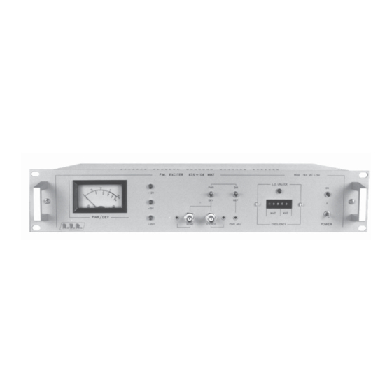
- Page 18 TEX20-NV Technical and Maintenance Manual " E U R O P A " V E R S I O N F R O N T P A N E L D E S C R I P T I O N ( F I G . 1 A )
- Page 19 TEX20-NV Technical and Maintenance Manual following operating parameters of the exciter: Direct and Reflected power, and Deviation VOLTAGES Led indicators that indicate the presence of the +20V, +15V and +12V MONO LEVEL Trimmer for the adjustment of MONO input level...
- Page 20 TEX20-NV Technical and Maintenance Manual FIG. 1A R.V.R. Elettronica S.r.l. (Bo) Pag. 20...
- Page 21 TEX20-NV Technical and Maintenance Manual following operating parameters of the exciter: Direct and Reflected power, and Deviation VOLTAGES Led indicators that indicate the presence of the +20V, +15V and +12V PWR/DEV The measurement made by the meter corresponds to the position of this...
- Page 22 TEX20-NV Technical and Maintenance Manual FIG. 1B R.V.R. Elettronica S.r.l. (Bo) Pag. 22...
- Page 23 TEX20-NV Technical and Maintenance Manual PLUG Mains voltage plug FUSE BLOCK Fuse block and line voltage selector. Use a small screwdriver to change the fuse or the line voltage. Rotate the block and position it for the desired voltage. INTERLOCK BNC connector.
- Page 24 TEX20-NV Technical and Maintenance Manual FIG. 2A R.V.R. Elettronica S.r.l. (Bo) Pag. 24...
- Page 25 TEX20-NV Technical and Maintenance Manual PLUG Mains voltage plug FUSE BLOCK Fuse block and line voltage selector. Use a small screwdriver to change the fuse or the line voltage. Rotate the block and position it for the desired voltage. INTERLOCK BNC connector.
- Page 26 TEX20-NV Technical and Maintenance Manual RDS encoder SCA 1 LEVEL Trimmer for the adjustment of SCA 1 input level SCA 1 INPUT BNC connector, unbalanced SCA 1 input or pilot output for internally selectable RDS encoder TELEMETRY TERMINALS 10-pin telemetry socket:...
- Page 27 TEX20-NV Technical and Maintenance Manual FIG. 2B R.V.R. Elettronica S.r.l. (Bo) Pag. 27...
- Page 28 TEX20-NV Technical and Maintenance Manual " E U R O P A " V E R S I O N T O P V I E W D E S C R I P T I O N ( P H O T O 1 ) ....
- Page 29 TEX20-NV Technical and Maintenance Manual PHOTO 1 R.V.R. Elettronica S.r.l. (Bo) Pag. 29...
- Page 30 TEX20-NV Technical and Maintenance Manual " U S A " V E R S I O N T O P V I E W D E S C R I P T I O N ( P H O T O 2 ) ....
- Page 31 TEX20-NV Technical and Maintenance Manual PHOTO 2 R.V.R. Elettronica S.r.l. (Bo) Pag. 31...
- Page 32 TEX20-NV Technical and Maintenance Manual FIG. 3 R.V.R. Elettronica S.r.l. (Bo) Pag. 32...
- Page 33 TEX20-NV Technical and Maintenance Manual TABLE C RECOMMENDED TEST EQUIPMENT INSTRUMENT MODEL SPECIFICATION Coaxial Load Resistor Bird Power rating 50W continuous Mod. 8085 Wattmeter Bird Power range : 100mW to 10KW Mod. 43 using Bird Plug-in-Elements Frequency range : 0.45 to...
- Page 34 TEX20-NV Technical and Maintenance Manual INSTALLATION 3.1 INTRODUCTION This chapter contains the information required for installation of the TEX20-N.V. exciter and for preliminary checks. 3.2 UNPACKING Remove the unit from its packaging and before any other operation, check for any damage that the unit may have suffered in transit and that all front and rear panel controls are functioning.
- Page 35 TEX20-NV Technical and Maintenance Manual Input), so that to obtain a reading of 75 KHz on the analog meter. 3.4 PRE-INSTALLATION Before the installation of the equipment (on the transmitter station), we suggest to you to execute a complete check on it, to avoid problems during the installation.
- Page 36 TEX20-NV Technical and Maintenance Manual Switch the power switch to the ON position and check that the both green voltages presence leds (2 Fig.1A and 1B) and the red UNLOCK led (12 Fig.1A and 7 Fig.1B) are both ON. Select the desired operating frequency using the corresponding selector (8 Fig.1A and 6 Fig.1B).
- Page 37 TEX20-NV Technical and Maintenance Manual To execute this operation see as reference SETUP 1. It’s advisable to start this procedure with the operating frequency set to 87.50MHz. When locked to this frequency, the PWR ADJ control should be adjusted for an output power of 10W.
- Page 38 TEX20-NV Technical and Maintenance Manual Disconnect right and left channels on the encoder and verify that the reading is now of about 7.5 KHz. Monophonic Transmission SETUP 3 Before to execute this operation see as reference SETUP4. Connect the signal source (audio mixer, receiver, compressor etc.) SETUP 4 to the MONO input (4 Fig.1A or 9 Fig.2B).
- Page 39 TEX20-NV Technical and Maintenance Manual quality. In the case of mono transmissions, the MPX input is available for frequencies between 40KHz and 100KHz ie. subcarriers for SCA, RDS etc., with a sensitivity of 0 dBm (775mVrms = 2.2Vpp, 600 Ohm) for deviation of 75KHz.
- Page 40 TEX20-NV Technical and Maintenance Manual MAINTENANCE 4.1 SAFETY REQUIREMENTS WARNING WARNING WARNING WARNING WARNING WARNING WARNING WARNING When the exciter is operational, removing the top cover will expose lethal voltages on the line voltage selector and heavy currents on the power supply filter terminals and power transistors.
- Page 41 TEX20-NV Technical and Maintenance Manual Main Card to the RF Power Amplifier module. Unscrew the nuts fixing the card. Remove the card upwards with great care. 4.5 EURO AUDIO INPUT CARD REPLACEMENT Open the top cover of the unit. Disconnect connectors CN3, CN4 and CN5 placed on the card.
- Page 42 TEX20-NV Technical and Maintenance Manual Disconnect fastons JP1 and JP2 situated on the bridge rectifier. Carefully lift out the power supply. FREQUENCY SELECTOR (CONTRAVES) CARD REPLACEMENT Open the top cover of the unit. Disconnect connector CN1 situated on the Contraves card.
- Page 43 TEX20-NV Technical and Maintenance Manual CALIBRATION PROCEDURE 5.1 MAIN CARD CALIBRATION After having replaced the Main Card and relevant connectors, carry out the following procedure (see SETUP5): SETUP 5 Connect a 50 Ohm, 20W dummy load to the RF output.
- Page 44 TEX20-NV Technical and Maintenance Manual FIG. 4 For USA version, connect together MONO(+) and MONO(-) inputs with a coaxial cable and connect its braided wire to ground. Now, through an oscilloscope on pin 7 of U1 and ground, adjust R20 trimmer to obtain minimum signal value (SETUP7).
- Page 45 TEX20-NV Technical and Maintenance Manual Verify on the meter that is present a reading of 75KHz, if not, adjust R33 trimmer. Connect an audio generator to the MPX input. 10) Inject a 400Hz, 0dBm (775mVrms, 2.2Vpp) tone into the MPX input.
- Page 46 5W. Now, disconnect the dummy load from exciter’s R.F. output. Verify the same reading on TEX20-NV’s meter, selecting a FWD PWR reading through relative selectors placed on the front panel; if the reading on the meter is different from 5W reads on wattmeter, adjust R5 trimmer placed on the EURO Audio Input card.
- Page 47 TEX20-NV Technical and Maintenance Manual APPENDIX A CIRCUIT DIAGRAMS, LAYOUTS AND BILLS OF MATERIAL This section contains circuit diagrams, layouts and bills of material of the modules which composing the equipment. For more information about each module see as reference Section 2.
- Page 48 TEX20-NV Technical and Maintenance Manual WIRING DIAGRAM Exciter Wiring Diagram ("EUROPA" Version) Pag. 49 Exciter Wiring Diagram ("USA" Version) Pag. 50 R.V.R. Elettronica S.r.l. (Bo) Pag. 48...
- Page 49 TEX20-NV Technical and Maintenance Manual EXCITER WIRING DIAGRAM ("EUROPA" VERSION) DIAGRAMMA DELLE CONNESIONI DELL'ECCITATORE (VERSIONE "EUROPA") R.V.R. Elettronica S.r.l. (Bo) Pag. 49...
- Page 50 TEX20-NV Technical and Maintenance Manual EXCITER WIRING DIAGRAM ("USA" VERSION) DIAGRAMMA DELLE CONNESIONI DELL'ECCITATORE (VERSIONE "USA") R.V.R. Elettronica S.r.l. (Bo) Pag. 50...
- Page 51 TEX20-NV Technical and Maintenance Manual MAIN CARD V.C.O. & Driver Section Circuit Diagram Pag. 52 V.C.O. & Driver Section Bill of Materials Pag. 53 Audio Section Circuit Diagram Pag. 56 Audio Section Bill of Materials Pag. 57 Synthesis Section Circuit Diagram Pag.
- Page 52 TEX20-NV Technical and Maintenance Manual R.V.R. Elettronica S.r.l. (Bo) Pag. 52...
- Page 53 TEX20-NV Technical and Maintenance Manual RF VCO and Driver Section Bill of Materials/Lista Componenti Pag. 1 Item Quantity Reference Part Description Part Order Code __________________________________________________________________________________________________ 4 R51,R53, 10 1% RESISTOR 1/4W 1% RSM1/4FH0010 R58,R80 1 R43 RESISTOR 1/4W 5% RSC1/4JH0022...
- Page 54 TEX20-NV Technical and Maintenance Manual RF VCO and Driver Section Bill of Materials/Lista Componenti Pag. 2 Item Quantity Reference Part Description Part Order Code __________________________________________________________________________________________________ 1 R70 RESISTOR 1/4W 5% RSC1/4JM0001 1 C70 CERAMIC CAPACITOR NP0 CKM2,2BJ600C 1 C50 27pF...
- Page 55 TEX20-NV Technical and Maintenance Manual RF VCO and Driver Section Bill of Materials/Lista Componenti Pag. 3 Item Quantity Reference Part Description Part Order Code __________________________________________________________________________________________________ 1 D7 Z6V8 ZENER DIODE 6.8V 0.4W DIZ6V80W4 1 Q5 BC237 NPN TRANSISTOR TRNBC237 2 Q6,Q10...
- Page 56 TEX20-NV Technical and Maintenance Manual R.V.R. Elettronica S.r.l. (Bo) Pag. 56...
- Page 57 TEX20-NV Technical and Maintenance Manual Audio Section Bill of Materials/Lista Componenti Pag. 1 Item Quantity Reference Part Description Part Order Code __________________________________________________________________________________________________ 4 R132,R134, 47 1% RESISTOR 1/4W 1% RSM1/4FH0047 R136,R137 1 R135 56 1% RESISTOR 1/4W 1% RSM1/4FH0056 1 R133...
- Page 58 TEX20-NV Technical and Maintenance Manual Audio Section Bill of Materials/Lista Componenti Pag. 2 Item Quantity Reference Part Description Part Order Code __________________________________________________________________________________________________ 1 R35 T47K TRIMMER REG. VERT. 10mm RVTD10VK0047 12 C5,C6,C7, 39pF CERAMIC CAPACITOR NP0 CKM390BJ600C C8,C9,C10, C11,C12,C14, C15,C16,C17...
- Page 59 TEX20-NV Technical and Maintenance Manual R.V.R. Elettronica S.r.l. (Bo) Pag. 59...
- Page 60 TEX20-NV Technical and Maintenance Manual Synthesis Section Bill of Materials/Lista Componenti Pag. 1 Item Quantity Reference Part Description Part Order Code __________________________________________________________________________________________________ 2 R103,R128 22 RESISTOR 1/4W 5% RSC1/4JH0022 1 R117 27 1% RESISTOR 1/4W 1% RSM1/4FH0027 3 R99,R100, 100 1%...
- Page 61 TEX20-NV Technical and Maintenance Manual Synthesis Section Bill of Materials/Lista Componenti Pag. 2 Item Quantity Reference Part Description Part Order Code __________________________________________________________________________________________________ 1 R148 RESISTOR 1/4W 5% RSC1/4JM0010 2 RR1,RR2 RR1K5 RESISTOR NETWORK RRR1/4JK01,5 1 C118 1n5P POLIESTER CAPACITOR CPE152BK101...
- Page 62 TEX20-NV Technical and Maintenance Manual Synthesis Section Bill of Materials/Lista Componenti Pag. 3 Item Quantity Reference Part Description Part Order Code __________________________________________________________________________________________________ 1 U7 SP8680 ECL DIVIDER CIDSP8680B 1 U5 4046 CMOS PHASE COMPARATOR CID4046 1 U16 4518 CMOS BCD DIVIDER...
- Page 63 TEX20-NV Technical and Maintenance Manual R.V.R. Elettronica S.r.l. (Bo) Pag. 63...
- Page 64 TEX20-NV Technical and Maintenance Manual POWER SUPPLY Circuit Diagram Pag. 65 Bill of Materials Pag. 66 Layout Pag. 68 R.V.R. Elettronica S.r.l. (Bo) Pag. 64...
- Page 65 TEX20-NV Technical and Maintenance Manual R.V.R. Elettronica S.r.l. (Bo) Pag. 65...
- Page 66 TEX20-NV Technical and Maintenance Manual Power SupplyBill of Materials/Lista Componenti Pag. 1 Item Quantity Reference Part Description Part Order Code __________________________________________________________________________________________________ 2 R24,R25 0.22$ RESISTOR 5W RAF005JH0,22 3 R3,R21,R26 10 1% RESISTOR 1/4W 1% RSM1/4FH0010 1 R28 RESISTOR 1/4W 5%...
- Page 67 TEX20-NV Technical and Maintenance Manual Power SupplyBill of Materials/Lista Componenti Pag. 2 Item Quantity Reference Part Description Part Order Code __________________________________________________________________________________________________ 2 C16,C21 33µF ELECTROLYTIC CAPACITOR CEA336BM350 1 C23 22000µF ELECTROLYTIC CAPACITOR CEA229PM630 3 L1,L2,L3 VK RF CHOKE IMPVK00A 1 F2...
- Page 68 TEX20-NV Technical and Maintenance Manual R.V.R. Elettronica S.r.l. (Bo) Pag. 68...
- Page 69 TEX20-NV Technical and Maintenance Manual CON-PA CARD Circuit Diagram Pag. 70 Bill of Materials Pag. 71 Layout Pag. 72 R.V.R. Elettronica S.r.l. (Bo) Pag. 69...
- Page 70 TEX20-NV Technical and Maintenance Manual R.V.R. Elettronica S.r.l. (Bo) Pag. 70...
- Page 71 TEX20-NV Technical and Maintenance Manual CON-PA Card Bill of Materials/Lista Componenti Pag. 1 Item Quantity Reference Part Description Part Order Code __________________________________________________________________________________________________ 1 CN1 34 P CONN. CONN. M 2*17 P 2.54 CNTMCSFC34P R.V.R. Elettronica S.r.l. (Bo) Pag. 71...
- Page 72 TEX20-NV Technical and Maintenance Manual R.V.R. Elettronica S.r.l. (Bo) Pag. 72...
- Page 73 TEX20-NV Technical and Maintenance Manual R.F. POWER AMPLIFIER Circuit Diagram Pag. 74 Bill of Materials Pag. 75 Layout Pag. 77 R.V.R. Elettronica S.r.l. (Bo) Pag. 73...
- Page 74 TEX20-NV Technical and Maintenance Manual R.V.R. Elettronica S.r.l. (Bo) Pag. 74...
- Page 75 TEX20-NV Technical and Maintenance Manual R.F. Power Amplifier Bill of Materials/Lista Componenti Pag. 1 Item Quantity Reference Part Description Part Order Code __________________________________________________________________________________________________ 2 R3,R4 3.9** RESISTOR 1W RSC001JH03,9 2 R5,R6 18** RESISTOR 1W RSC001JH0018 3 R1,R8,R10 18# RESISTOR 2W...
- Page 76 TEX20-NV Technical and Maintenance Manual R.F. Power Amplifier Bill of Materials/Lista Componenti Pag. 2 Item Quantity Reference Part Description Part Order Code __________________________________________________________________________________________________ 6 C39,C40, 1nFPAS CERAMIC THROUGH CAPAC. CDP102XK500 C41,C46, C48,C49 6 C1,C9,C13, CERAMIC CAPACITOR CKM472BK600P C28,C37,C38 1 C10 10µF...
- Page 77 TEX20-NV Technical and Maintenance Manual R.V.R. Elettronica S.r.l. (Bo) Pag. 77...
- Page 78 TEX20-NV Technical and Maintenance Manual FREQUENCY SELECTOR CARD (MOD. TSW-1) Circuit Diagram Pag. 79 Bill of Materials Pag. 80 Layout Pag. 81 R.V.R. Elettronica S.r.l. (Bo) Pag. 78...
- Page 79 TEX20-NV Technical and Maintenance Manual R.V.R. Elettronica S.r.l. (Bo) Pag. 79...
- Page 80 TEX20-NV Technical and Maintenance Manual Frequency Selector Card Bill of Materials/Lista Componenti Pag. 1 Mod. TSW-1 Item Quantity Reference Part Description Part Order Code __________________________________________________________________________________________________ 1 CN1 26P CONN. CONN. M 2*13 P 2.54 CNTMCSFC26P 5 CNTR1, CONTRAVES COMMUTATORI BCD 15mm...
- Page 81 TEX20-NV Technical and Maintenance Manual R.V.R. Elettronica S.r.l. (Bo) Pag. 81...
- Page 82 TEX20-NV Technical and Maintenance Manual FREQUENCY SELECTOR CARD (MOD. TSW-3) Circuit Diagram Pag. 83 Bill of Materials Pag. 84 Layout Pag. 85 R.V.R. Elettronica S.r.l. (Bo) Pag. 82...
- Page 83 TEX20-NV Technical and Maintenance Manual R.V.R. Elettronica S.r.l. (Bo) Pag. 83...
- Page 84 TEX20-NV Technical and Maintenance Manual Frequency Selector Card Bill of Materials/Lista Componenti Pag. 1 Mod. TSW-3 Item Quantity Reference Part Description Part Order Code __________________________________________________________________________________________________ 1 CN1 26P CONN. CONN. M 2*13 P 2.54 CNTMCSFC26P 5 CNTR1, CONTRAVES COMMUTATORI BCD 15mm...
- Page 85 TEX20-NV Technical and Maintenance Manual R.V.R. Elettronica S.r.l. (Bo) Pag. 85...
- Page 86 TEX20-NV Technical and Maintenance Manual USA AUDIO INPUT CARD Circuit Diagram Pag. 87 Bill of Materials Pag. 88 Layout Pag. 89 R.V.R. Elettronica S.r.l. (Bo) Pag. 86...
- Page 87 TEX20-NV Technical and Maintenance Manual R.V.R. Elettronica S.r.l. (Bo) Pag. 87...
- Page 88 TEX20-NV Technical and Maintenance Manual USA Audio Input Card Bill of Materials/Lista Componenti Pag. 1 Item Quantity Reference Part Description Part Order Code __________________________________________________________________________________________________ 3 R1,R2,R3 1K 1% RESISTOR 1/4W 1% RSM1/4FK0001 4 R5,R6,R7,R8 TL10K TRIMMER REG. VERT. 15mm RVTD15VK0010...
- Page 89 TEX20-NV Technical and Maintenance Manual R.V.R. Elettronica S.r.l. (Bo) Pag. 89...
- Page 90 TEX20-NV Technical and Maintenance Manual EURO AUDIO INPUT CARD Circuit Diagram Pag. 91 Bill of Materials Pag. 92 Layout Pag. 93 R.V.R. Elettronica S.r.l. (Bo) Pag. 90...
- Page 91 TEX20-NV Technical and Maintenance Manual R.V.R. Elettronica S.r.l. (Bo) Pag. 91...
- Page 92 TEX20-NV Technical and Maintenance Manual EURO Audio Input Card Bill of Materials/Lista Componenti Pag. 1 Item Quantity Reference Part Description Part Order Code __________________________________________________________________________________________________ 3 R2,R3,R9 2K2 1% RESISTOR 1/4W 1% RSC1/4FK02,2 1 R6 10K 1% RESISTOR 1/4W 1% RSM1/4FK0010...
- Page 93 TEX20-NV Technical and Maintenance Manual R.V.R. Elettronica S.r.l. (Bo) Pag. 93...
- Page 94 TEX20-NV Technical and Maintenance Manual CLIPPER CARD MPX-MONO Circuit Diagram Pag. 95 Bill of Materials Pag. 96 Layout Pag. 97 R.V.R. Elettronica S.r.l. (Bo) Pag. 94...
- Page 95 TEX20-NV Technical and Maintenance Manual R.V.R. Elettronica S.r.l. (Bo) Pag. 95...
- Page 96 TEX20-NV Technical and Maintenance Manual Clipper Card MPX-Mono Bill of Materials/Lista Componenti Pag. 1 Item Quantity Reference Part Description Part Order Code __________________________________________________________________________________________________ 1 R6 100 1% RESISTOR 1/4W 1% RSM1/4FH0100 1 R7 1K 1% RESISTOR 1/4W 1% RSM1/4FK0001 1 R15...
- Page 97 TEX20-NV Technical and Maintenance Manual R.V.R. Elettronica S.r.l. (Bo) Pag. 97...
- Page 98 TEX20-NV Technical and Maintenance Manual TCXO CARD Circuit Diagram Pag. 99 Bill of Materials Pag. 100 Layout Pag. 101 R.V.R. Elettronica S.r.l. (Bo) Pag. 98...
- Page 99 TEX20-NV Technical and Maintenance Manual R.V.R. Elettronica S.r.l. (Bo) Pag. 99...
- Page 100 TEX20-NV Technical and Maintenance Manual TCXO Card Bill Of Materials Page Item Quantity Reference Part ____________________________________________________________________________________________________ 2 C1,C2 0.1uF 1 FIX1 FIX35 1 JP1 STM06SO 8 J1,J2,J3,J4,J5,J6,J7,J8 JSMD 1 Q1 MMBFJ310 1 Q2 BC857 1 R1 1 R2 1 R3...
- Page 101 TEX20-NV Technical and Maintenance Manual © Copyright 1993 Fourth Edition - May '97 Created By D’Alessio D. & Morotti M. R.V.R. Elettronica S.r.l. (Bo) Via del Fonditore 2/2c - 40138 - Bologna (Italy) National: Phone 051/601.05.06 r.a. Fax 051/601.11.04 International : Phone +39 51-601.05.06 Fax +39 51- 601.11.04...
- Page 102 TEX20-NV Technical and Maintenance Manual © Copyright 1993 Fourth Edition - May '97 Created By D’Alessio D. & Morotti M. R.V.R. Elettronica S.r.l. (Bo) Via del Fonditore 2/2c - 40138 - Bologna (Italy) National: Phone 051/601.05.06 r.a. Fax 051/601.11.04 International : Phone +39 51-601.05.06 Fax +39 51- 601.11.04...
- Page 103 TEX 20 NV APPENDIX Description RVR Code Vers. Pages Power Supply PSSW-PTNV Appendix Rev. 0.1 - 15/05/02...
- Page 104 TEX 20 NV Pagina lasciata intenzionalmente in bianco Rev. 0.1 - 15/05/02 Appendix...
- Page 105 TEX 20 NV Appendice Tecnica Rev. 0.1 - 15/05/02 PSSWPTNV - 1 / 6...
- Page 106 TEX 20 NV 2 / 6 - PSSWPTNV Rev. 0.1 - 15/05/02 Technical Appendix...
- Page 107 TEX 20 NV POWER SUPPLY TEX20 TEX30 Bill Of Materials Page Item Q.ty Reference Part ____________________________________________________________________________________________ C1,C12 CT1/35 4.7UF C5,C13,C16,C18,C29,C30, CM.1UF C31,C32,C33,C34,C35,C39, C50,C56,C58 C7,C8,C9,C10,C11,C24,C25, 1000/50 C14,C27,C40 CD1KPF C15,C17,C48,C49 220/25 CP.47UF C28,C54,C55 EKR470/25 CP33KPF CD.1UF C43,C44 CM100PF C45,C46,C57 CP47KPF 220/40 4N7UF CP.1UF 15V/1W 20V-0.5W...
- Page 108 TEX 20 NV 4N26 STRIP2 KRA6 JUMPER CON26A L1,L3 T1804 Q1,Q2 BC237 IRFZ44A R3,R15,R16,R21,R44 R9,R10,R12,R18,R20,R22, R26,R57,R60 560R R13,R53 330R R17,R19,R23,R45 R37,R63 1K32 560K MIA22UH R1/5W R50,R61 10R/1W 2K62 R62,R67 820R 4 / 6 - PSSWPTNV Rev. 0.1 - 15/05/02 Technical Appendix...
- Page 109 TEX 20 NV 12K7 82R/2W HC5K LM7812 IR2127 LT1076CT UC3823 LM358 Appendice Tecnica Rev. 0.1 - 15/05/02 PSSWPTNV - 5 / 6...
- Page 110 TEX 20 NV Pagina lasciata intenzionalmente in bianco This page was intentionally left blank 6 / 6 - PSSWPTNV Rev. 0.1 - 15/05/02 Technical Appendix...
Need help?
Do you have a question about the TEX20-NV and is the answer not in the manual?
Questions and answers