Table of Contents
Advertisement
Quick Links
Advertisement
Table of Contents

Related Manuals for R.V.R. Elettronica PTX30 UHT/S3


Summary of Contents for R.V.R. Elettronica PTX30 UHT/S3
- Page 1 PTX30 UHT /S3 User Manual Manifactured by Italy...
- Page 2 Reason Editor 10/12/2001 New version J. Berti PTX30 UHT /S3 - User Manual Version 5.0 © Copyright 1993-2001 R.V.R. Elettronica SpA Via del Fonditore 2/2c - 40138 - Bologna (Italia) Telefono: +39 051 6010506 Fax: +39 051 6011104 Email: info@rvr.it Web: www.rvr.it...
- Page 3 Limitations of use can apply in respect of operating freuency, transmitter power and/or channel spacing. Declaration of Conformity Hereby, R.V.R. Elettronica SpA, declares that this FM transmitter is in compliance with the essential requirements and other relevant provisions of Directive 1999/5/EC.
- Page 4 This page intentionally left blank...
-
Page 5: Table Of Contents
PTX30 UHT /S3 Table of Contents 1. Preliminary Instructions 2. Warranty 3. First Aid 3.1 Treating electric shocks 3.2 Treating electric burns 4. General Description 5. Quick Start 5.1 Preparation 5.2 Operation 6 External Description 6.1 Front Panel 6.2 Rear panel 6.3 Connectors description 7. - Page 6 PTX30 UHT /S3 This page was intentionally left blank Rev. 5.0 - 10/12/2001 User Manual...
-
Page 7: Preliminary Instructions
R.V.R. Elettronica SpA does not assume responsibility for injuries to persons or damage to items caused by improper use or incorrect usage procedures, whether the users are experienced or not. - Page 8 PTX30 UHT /S3 This page was intentionally left blank Rev. 5.0 - 10/12/2001 User Manual 2 / 36...
-
Page 9: Warranty
PTX30 UHT /S3 2. Warranty The guarantee, which is for 12 (twelve) months, is valid for any R.V.R. Elettronica product. On components such as tubes for final amplifiers, the manufacturer’s guarantee applies. R.V.R. Elettronica extends all transferable original guarantees to its own products. - Page 10 PTX30 UHT /S3 Replacement of parts under guarantee or spare parts can be ordered from the following address: R.V.R. Elettronica SpA Via del Fonditore, 2/2c 40138 BOLOGNA ITALY Tel. +39 051 6010506 quoting type, model and serial number of the device.
-
Page 11: First Aid
PTX30 UHT /S3 3. First Aid Personnel involved in the installation, use, and maintenance of the equipment must be familiar with the theory and practice of first aid. 3.1 Treating electric shocks 3.1.1 If the victim is inconscious Follow the first aid principles described below. •... -
Page 12: Treating Electric Burns
PTX30 UHT /S3 • Do not interrupt the cardiac massage during the artificial respiration. • Call a doctor as soon as possible 3.1.2 If the victim is conscious • Cover the victim with a blanket Keep him calm. • Loosen the victim’s clothes and keep him lying down •... -
Page 13: General Description
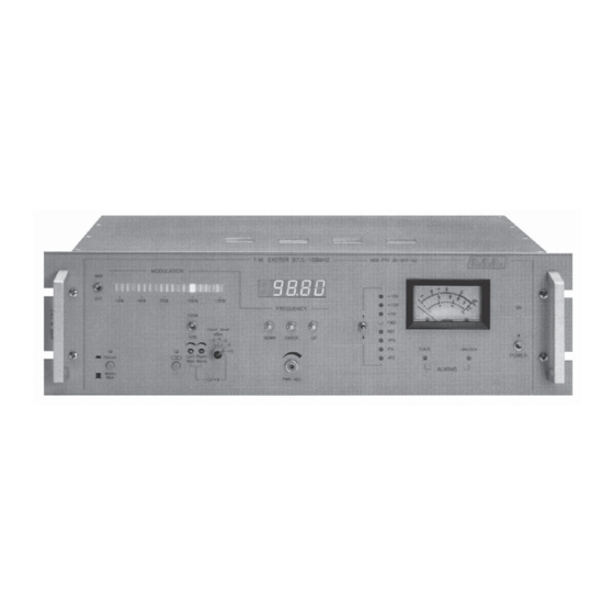
PTX30 UHT /S3 4. General Description The PTX30 is contained in a 19" 3U rack, internally assembled with modules mounted on a main chassis, all interconnected with connectors, allowing easy servicing and replacement. On the front panel there are the controls for output power and audio input level and meters for the main parameters. - Page 14 PTX30 UHT /S3 These circuits provide the automatic output power control, maintaining a flat power output response over the entire frequency range and the protection of the output stage against an excess of SWR and/or a short circuit on the feeder or the antenna. The RF final amplifier is broadband and guarantees an output level between 2 and 30 Watt over the entire frequency range.
-
Page 15: Quick Start
PTX30 UHT /S3 5. Quick Start This chapter gives a concise view of the points that are necessary for the installation of the device. If any item is not completely clear, for example when you use the exciter for the first time, we strongly suggest to read throughly the manual. 5.1 Preparation Unpack the transmitter and before any other operation check the unit for any shipping damage and check that all the controls and connectors on the front and... -
Page 16: Operation
PTX30 UHT /S3 figure 5.1 Connect a dummy load with a continuous power dissipation of 30 W or more to the R.F. OUT connector on the rear panel. It’s preferable to connect also a through wattmeter, to check the reading of the internal wattmeter (see figure 5.1). Connect to the rear input "REMOTE"... - Page 17 PTX30 UHT /S3 Note that if you push the UP and DOWN switches momentarily, you move the last digit one step each time, if you keep the switch pushed the digits change continuously. When the display reaches one extreme of the frequency it range jumps automatically to the opposite extreme.
- Page 18 PTX30 UHT /S3 Reconnect the dummy load and verify that the SWR led goes off, the meter indicates 0 reflected power and the forward power is 30W. Close the switch on the REMOTE input and verify that the output power drops immediately to 0.
- Page 19 PTX30 UHT /S3 Operating with internal stereo coder Insert the pilot tone confirmed by the corresponding led, than insert the Stereo function confirmed by the corresponding led. Select LEFT/RIGHT audio input sensitivity with regard to the level supplied from the source used and onnect the source to the “LEFT/RIGHT” inputs (these inputs are balanced).
- Page 20 PTX30 UHT /S3 Place the INPUT LEVEL command at the desired level. Position on 100%. Set the output level of the device connected to PTX30-UHT-S3 to just switch on the first red led of the bar graph (with a variable amplitude signal as a music). This indicates a Max.
-
Page 21: External Description
PTX30 UHT /S3 6 External Description This chapter describes the elements of the front and rear panels of the PTX30 UHT /S3. 6.1 Front Panel Figure 6.1 [1] BAR/DOT Selector of operation mode (BAT/DOT) for modulation meter. [2] STEREO/MONO-MPX Selector for “STEREO” operation or “MONO/MPX”. [3] MODULATION Modulation meter by “LED BAR”. - Page 22 PTX30 UHT /S3 [17] METER Analog meter used to monitor the parameters of the exciter such as: Direct power Reflected power Deviation power Right Input level Left MPX input level [18] POWER On/Off power switch [19] ON A.C. power “ON” indicator Rev.
-
Page 23: Rear Panel
PTX30 UHT /S3 6.2 Rear panel Figura 6.2 [1] PLUG A.C. power plug [2] FUSE BLOCK Fuse block & voltage. Use a small screwdriver to change fuse or voltage setting. turn block and place desired operating voltage next to arrow. [3] RS232C (optional) RS232C communication line to control or receive status of the exciter. -
Page 24: Connectors Description
PTX30 UHT /S3 6.3 Connectors description 6.3.1 RS 232 Tipo: DB9 female TX_D RX_D 6.3.2 Left (MONO) / Right (MPX Bal) Type: XLR female Signal (+) inphase Signal (-) return Rev. 5.0 - 10/12/2001 User Manual 18 / 36... -
Page 25: Technical Specifications
PTX30 UHT /S3 7. Technical Specifications 7.1 Mechanical Specifications Panel size 483 mm (19.0”) x 132.5 mm (5.2”) Depth 345.0 mm (13.7”) Weight 13 Kg -10 °C ÷ 50 °C Temperature range 7.2 Electrical Specifications A.C. power supply 100-130 V, 50-60 Hz 198-250 V, 50-60 Hz Power Consumption approx 140VA... - Page 26 PTX30 UHT /S3 This page was intentionally left blank Rev. 5.0 - 10/12/2001 User Manual 20 / 36...
-
Page 27: Identification And Access To The Modules
PTX30 UHT /S3 8. Identification and access to the modules 8.1 Modules identification (upper view) Figure 8.1 shows the upper view of the internal of the exciter. The components are described below. Figure 8.1 [1] Audio input card [2] R.F. power amplifier [3] Fan [4] Power supply [5] Main card... -
Page 28: Modules Identification (Bottom View)
PTX30 UHT /S3 8.2 Modules identification (bottom view) Figure 8.2 shows the upper view of the internal of the exciter. The components are described below. Figure 8.2 [1] Power supply [2] Fan [3] R.F. power amplifier [4] Audio input card [5] Anameter [6] C.P.U. -
Page 29: Access To The Modules
PTX30 UHT /S3 8.3 Access to the modules ATTENTION: opening the device, points with dangerous voltages and currents are exposed. Always disconnect the mains supply before removing the covers or taking away any part of the piece of equipment. Remove all the screws on the upper cover of the exciter. After taking away the cover, identify with the help of figures 8.1 and 8.2, the components of the exciter. - Page 30 PTX30 UHT /S3 • Disconnect the shielded cable connecting the Main Card and the R.F. Power Amplifier. • Unscrew the bolts that hold the board in place. • Carefully remove the board. 8.3.2.4 Audio input card replacement • Open the top and bottom covers. •...
- Page 31 PTX30 UHT /S3 • Disconnect J1 and J2 from the CPU board. • Remote the two screws of the CPU shielded box and take away the box. • Carefully take away the CPU board. 8.3.2.8 Power supply replacement • Open the top and bottom covers. •...
- Page 32 PTX30 UHT /S3 This page was intentionally left blank Rev. 5.0 - 10/12/2001 User Manual 26 / 36...
-
Page 33: Working Principles
PTX30 UHT /S3 9. Working principles Figure 9.1 gives an overview of modules and connections composing the PTX30 UHT /S3. Figure 9.1 In the following you will find a short description of the functionalities of each module. 9.1 Power supply This circuit is composed of one board placed over an heat-sinks perpendicularly mounted, fitted in the central part of the intermediate sub-chassis. -
Page 34: Audio Input Card
PTX30 UHT /S3 The +12V line supplies the driver stage of the RF power amplifier and the variable voltage (2-24V) supplies the final stage of the Power Amplifier. The variable voltage applied to the final stage is regulated by the external control "PWR ADJ"... -
Page 35: Main Card
PTX30 UHT /S3 In the mixer mode (MONO-MPX) the section of stereo coding is by-passed and the "RIGHT" input can accept a mono signal, while the "LEFT" signal accepts a multiplex signal with a 100KHz bandpass; the SCA inputs remain the same. Three peak-to-peak detectors allow the analog meter to read the levels of the "RIGHT/MONO"... -
Page 36: Modmeter
PTX30 UHT /S3 9.6 Modmeter You can find this board on the left side of the front panel. This circuit displays the frequency deviation of your signal, measuring the rectified audio signal that is injected in the VCO’s varicaps. A switch selects the gain of the meter between two levels (100% and 10%), thus obtaining a more exact reading over low deviation levels (e.g.. -
Page 37: Cpu
PTX30 UHT /S3 9.8 CPU The CPU board is installed on the front panel in the central position, and includes the microcontroller (68HC11) and the related components, a led display and the buttons for the frequency setting. This circuit translates the number corresponding to the selected frequency into a binary code that is sent to the PLL programmable dividers to allow the VCO to lock on the right frequency. - Page 38 PTX30 UHT /S3 This page was intentionally left blank Rev. 5.0 - 10/12/2001 User Manual 32 / 36...
-
Page 39: Adjustment Procedure
PTX30 UHT /S3 10. Adjustment Procedure 10.1 Stereo coder adjustment After changing a stereo coder board it’s necessary to make the following checks and adjustments (see figure 10.1): figure 10.1 Select 0dBm with the INPUT LEVEL selector (with stereo coder and pilot tone •... -
Page 40: Main Card Adjustment
PTX30 UHT /S3 • Disconnect the audio signals on both channels and leave the PILOT TONE inserted; verify that a deviation of 6.5 to 7.5KHz is present. This value can be adjusted with P6 on the coder board. Disconnect the audio signal from one channel and verify that the output level of •... -
Page 41: Power Supply Adjustment
PTX30 UHT /S3 10.4 Power supply adjustment The adjustments on the power supply after a replacement are the same performed when a R.F. power module is changed. Follow points 1, 2, 3, 4, 5, 6, 7, 8, of R.F. power amplifier replacement. 10.5 R.F. -
Page 42: Anameter Adjustment
PTX30 UHT /S3 10.8 Anameter adjustment After the board replacament it’s necessary to check all the adjustments for the measurements performed by this board. figure 10.3 • Connect an audio generator to the L and R inputs with an output of 400Hz at 0 •... -
Page 43: Appendix
PTX30 UHT /S3 Appendix A Piani di montaggio, schemi elettrici, liste componenti / Component layouts, schematics, bills of material Questa parte del manuale contiene i dettagli tecnici riguardanti la costruzione delle singole schede componenti il PTX30 UHT /S3. L’appendice è composta dalle seguenti sezioni: This part of the manual contains the technical details about the different boards of the PTX30 UHT /S3 . - Page 44 PTX30 UHT /S3 Pagina lasciata intenzionalmente in bianco This page intentionally left blank 5.0 - 10/12/01 User Manual 2 / 2 Technical Appendix...
- Page 45 PTX30 UHT /S3 Versione precedente, solo per riferimento Former version, for reference only Appendice Tecnica Rev. 1.0 - 10/12/01 WIRING DIAGRAMS - 1 / 2...
- Page 46 PTX30 UHT /S3 Versione precedente, solo per riferimento Former version, for reference only 2 / 2 - WIRING DIAGRAMS Rev. 1.0 - 10/12/01 Technical Appendix...
- Page 47 PTX30 UHT /S3 Appendice Tecnica Rev. 1.0 - 10/12/01 CSAUDIOCTE - 1 / 4...
- Page 48 PTX30 UHT /S3 2 / 4 - CSAUDIOCTE Rev. 1.0 - 10/12/01 Technical Appendix...
- Page 49 PTX30 UHT /S3 Audio Input Card Circuit Diagram Bill Of Materials Page Item Q.ty Reference Part Description PART ORDER CDE ___________________________________________________________________________________________________ R3,R4,R5,R6,R7,R8 1K 1% RESISTOR 1/4W 1% RSM1/4FK0001 C1,C2,C3,C4,C5,C6,C7,C8, 33PF CERAMIC CAPACITOR NP0 CKM330BJ600C C9,C10,C11,C12 C13,C14,C15,C16,C17,C18, 0.1UF CERAMIC CAPACITOR CKM104BK600P C19,C20,C21,C22,C23,C24 L1,L2,L3,L4,L5,L6 RF CHOKE...
- Page 50 PTX30 UHT /S3 Pagina lasciata intenzionalmente in bianco This page was intentionally left blank 4 / 4 - CSAUDIOCTE Rev. 1.0 - 10/12/01 Technical Appendix...
- Page 51 PTX30 UHT /S3 Appendice Tecnica Rev. 1.0 - 10/12/01 CSMAINPTX30 - 1 / 8...
- Page 52 PTX30 UHT /S3 2 / 8 - CSMAINPTX30 Rev. 1.0 - 10/12/01 Technical Appendix...
- Page 53 PTX30 UHT /S3 Main Card (Audio Sect.) Circuit Diagram Bill Of Materials Page Item Q.ty Reference Part Description Part Order Code _________________________________________________________________________________________________ R1,R3 10 1% RESISTOR 1/4W 1% RSM1/4FH0010 56 1% RESISTOR 1/4W 1% RSM1/4FH0056 R61,R62,R66,R68,R72 100 1% RESISTOR 1/4W 1% RSM1/4FH0100 150 1% RESISTOR 1/4W 1%...
- Page 54 PTX30 UHT /S3 4 / 8 - CSMAINPTX30 Rev. 1.0 - 10/12/01 Technical Appendix...
- Page 55 PTX30 UHT /S3 Main Card (R.F. Sect.) Circuit Diagram Bill Of Materials Page Item Quantity Reference Part Description Part Order Code _____________________________________________________________________________________________ R112 4.7* RESISTOR 1/2W 5% RSC1/2JH04,7 R92,R96,R102,R128 10 1% RESISTOR 1/4W 1% RSM1/4FH0010 22 1% RESISTOR 1/4W 1% RSM1/4FH0022 R110,R111 27 1%...
- Page 56 PTX30 UHT /S3 Z6V8 ZENER DIODE 6.8V 0.4W DIZ6V80W4 78L09 POS. STABILIZER 100mA CIL78L09 Q6,Q13 BC237 NPN TRANSISTOR TRNBC237 Q14,Q15 BCY59 NPN TRANSISTOR TRNBCY59 Q8,Q9,Q10 2N918 NPN RF TRANSISTOR TRN2N918 BFR96 NPN RF TRANSISTOR TRNBFR96 Q11,Q12 2N3866 RF POWER TRANSISTOR TRN2N3866 J310 FET TRANSISTOR...
- Page 57 PTX30 UHT /S3 Appendice Tecnica Rev. 1.0 - 10/12/01 CSMAINPTX30 - 7 / 8...
- Page 58 PTX30 UHT /S3 Main Card (Synthesis Sect.) Circuit Diagram Bill Of Materials Page Item Quantity Reference Part Description Part Order Code _________________________________________________________________________________________________ R142 RESISTOR 1/4W 5% RSC1/4JH0022 R143 22 1% RESISTOR 1/4W 1% RSM1/4FH0022 R147,R148,R171 100 1% RESISTOR 1/4W 1% RSM1/4FH0100 R144 150 1%...
- Page 59 PTX30 UHT /S3 Appendice Tecnica Rev. 1.0 - 10/12/01 PSSWPTX30 - 1 / 6...
- Page 60 PTX30 UHT /S3 2 / 6 - PSSWPTX30 Rev. 1.0 - 10/12/01 Technical Appendix...
- Page 61 PTX30 UHT /S3 POWER SUPPLY PTX30 PTX30UHT PTRLNV Bill Of Materials Page Item Q.ty Reference Part ___________________________________________________ C1,C12 CT1/35 4.7UF C3,C4 CM10NF C5,C6,C13,C16,C18,C22, CM.1UF C29,C30,C31,C32,C33,C34, C35,C36,C37,C38,C39,C50, C56,C58 C7,C8,C9,C10,C11,C24,C25, 1000/50 C14,C27,C40 CD1KPF C15,C17,C19,C21,C48,C49 220/25 CP.47UF C23,C43,C44 CM100PF C28,C54,C55 EKR470/25 CP33KPF CD.1UF C45,C46,C57 CP47KPF 220/40...
- Page 62 PTX30 UHT /S3 F1,F2,F3,F4,F5,F7,F8 DSS-310 L2,F9,F13,F14,F16 WK200 F10,F11,F12 BL02 4N26 JP3,JP8,JP9 STRIP2 KRA6 JUMPER CON34A CON26A L1,L3 T1804 220UH Q1,Q2 BC237 BC488 IRFZ44A R3,R4,R15,R16,R21,R39, R5,R6,R9,R10,R12,R18,R20, 10K R22,R26,R31,R32,R47,R57, R7,R54,R55 100K R8,R65 560R 330R R17,R19,R23,R28,R45 R24,R33,R34 4 / 6 - PSSWPTX30 Rev. 1.0 - 10/12/01 Technical Appendix...
- Page 63 PTX30 UHT /S3 R30,R43 R35,R36 R37,R63 1K32 100R 560K MIA22UH R1/5W R50,R61 10R/1W 2K62 R62,R67 820R 12K7 87W20K 82R/2W TR1,TR3 HC5K LM7812 OP07 LM7805 UA78S40DC U5,U9 LM358 IR2127 LT1076CT UC3823 Appendice Tecnica Rev. 1.0 - 10/12/01 PSSWPTX30 - 5 / 6...
- Page 64 PTX30 UHT /S3 Pagina lasciata intenzionalmente in bianco This page was intentionally left blank 6 / 6 - PSSWPTX30 Rev. 1.0 - 10/12/01 Technical Appendix...
- Page 65 PTX30 UHT /S3 Versione precedente, solo per riferimento Former version, for reference only Appendice Tecnica Rev. 1.0 - 10/12/01 CSPS1PTX30 - 1 / 6...
- Page 66 PTX30 UHT /S3 Versione precedente, solo per riferimento Former version, for reference only 2 / 6 - CSPS2PTX30 Rev. 1.0 - 10/12/01 Technical Appendix...
- Page 67 PTX30 UHT /S3 Power Supply Circuit Diagram Bill Of Materials Page Item Q.ty Reference Part Description Part Order Code _________________________________________________________________________________________________ C47,C48,C49,C50 0.1UF CERAMIC CAPACITOR CKM104BK600P C13,C14 10UF ELECTROLYTIC CAPACITOR CEA106AM350 C2,C6,C8,C10 47UF ELECTROLYTIC CAPACITOR CEA476BM630 C3,C7,C9,C11 100UF ELECTROLYTIC CAPACITOR CEA107BM350 2200UF ELECTROLYTIC CAPACITOR CEA228CM350 C1,C4...
- Page 68 PTX30 UHT /S3 Versione precedente, solo per riferimento Former version, for reference only 4 / 6 - CSPS2PTX30 Rev. 1.0 - 10/12/01 Technical Appendix...
- Page 69 PTX30 UHT /S3 Versione precedente, solo per riferimento Former version, for reference only Appendice Tecnica Rev. 1.0 - 10/12/01 CSPS1PTX30 - 5 / 6...
- Page 70 PTX30 UHT /S3 POWER SUPPLY CIRCUIT DIAGRAM Bill Of Materials Page Item Quantity Reference Part Description Part Order Code __________________________________________________________________________________________________ R34,R35 0.22$ RESISTOR 5W RAF005JH0,22 R32,R40,R50,R55 10 1% RESISTOR 1/4W 1% RSM1/4FH0010 RESISTOR 1/4W 5% RSC1/4JH0220 220* RESISTOR 1/2W 5% RSC1/2JH0220 R24,R27 330 1% RESISTOR 1/4W 5% RSM1/4FH0330...
- Page 71 PTX30 UHT /S3 Appendice Tecnica Rev. 1.0 - 10/12/01 CSPA30W-1 - 1 / 4...
- Page 72 PTX30 UHT /S3 2 / 4 - CSPA30W-1 Rev. 1.0 - 10/12/01 Technical Appendix...
- Page 73 PTX30 UHT /S3 CSPA30W-1 Bill Of Materials Page1 ItemQ.ty Reference Part ________________________________________________________________ CN1,CN3 BNC TELAIO N TELAIO T40pF C1,C9,C13,C28,C37,C38 C11,C2 39pF 47pF 100pF C5,C6,C7,C23,C27,C28,C33 12pF C8,C34 C9A,C20 0.1uF 10uF 15pF 150pFHQ C15,C16,C17,C18 82pF 1nFUNELCO 680pFHQ C25B,C25A,C25 33pF C26C,C26B,C26A,C26 18pF 100uF C29,C30,C31,C32 27pF C36,C47...
- Page 74 PTX30 UHT /S3 Pagina lasciata intenzionalmente in bianco This page was intentionally left blank 4 / 4 - CSPA30W-1 Rev. 1.0 - 10/12/01 Technical Appendix...
- Page 75 PTX30 UHT /S3 Appendice Tecnica Rev. 1.0 - 10/12/01 CSCON-PA1 - 1 / 4...
- Page 76 PTX30 UHT /S3 2 / 4 - CSCON-PA1 Rev. 1.0 - 10/12/01 Technical Appendix...
- Page 77 PTX30 UHT /S3 CON-PA CARD Bill Of Materials Page Item Quantity Reference Part Description Part Order Code _________________________________________________________________________________________________ 34 PIN CONN. CONN. M 2*17P 2.54 CNTMCSFC34P Appendice Tecnica Rev. 1.0 - 10/12/01 CSCON-PA1 - 3 / 4...
- Page 78 PTX30 UHT /S3 Pagina lasciata intenzionalmente in bianco This page was intentionally left blank 4 / 4 - CSCON-PA1 Rev. 1.0 - 10/12/01 Technical Appendix...
- Page 79 PTX30 UHT /S3 Technical Appendix Rev. 1.0 - 10/12/01 CSSDC30A003 - 1 / 6...
- Page 80 PTX30 UHT /S3 2 / 6 - CSSDC30A003 Rev. 1.0 - 10/12/01 Technical Appendix...
- Page 81 PTX30 UHT /S3 Technical Appendix Rev. 1.0 - 10/12/01 CSSDC30A003 - 3 / 6...
- Page 82 PTX30 UHT /S3 4 / 6 - CSSDC30A003 Rev. 1.0 - 10/12/01 Technical Appendix...
- Page 83 PTX30 UHT /S3 SLSDC30A002 Bill Of Materials Page1 ItemQuantity Reference Part _______________________________________________________________________________________________ COD1 IRV30CT C1,C25,C26,C27,C45,C46, 10uF C2,C5,C10,C11,C12,C13, 0.1uF C20,C21,C23,C28,C29,C32, C37,C38,C43,C44,C49,C52 C3,C4,C48,C54 47uF C6,C7,C8,C9,C31,C53 100uF C17,C14 C18,C15 C19,C16 100pF C22,C24,C36 2.2uF 220uF C33,C34,C35 10nF C39,C40 47pF CV40pF CV20pF C50,C51 22pF D1,D5 LED-G5 SW2,R2,D2,SW3,R3,D3,SW4, R4,D4...
- Page 84 PTX30 UHT /S3 R18,R25,R58 14K0 R27,R20 7K15 R29,R22 2K49 R30,R23 1K78 R35P,R36 82K5 R45,R43 22K1 R46,R44 680H0 R47,R49,R81 470K0 R54,R55,R115 8K20 R56,R57,R116 39K0 R67,R68,R69 49K9 124K0 R76,R95,R96 47K0 R78,R79,R80 22K0 4K42 R98,R100,R112 2K20 R101 3K30 R102,R109 100K0 R103 56K0 R104 2M20 R117,R118 604H0...
- Page 85 PTX30 UHT /S3 Versione precedente, solo per riferimento Former version, for reference only Appendice Tecnica Rev. 1.0 - 10/12/01 CSSCHSDC30A - 1 / 4...
- Page 86 PTX30 UHT /S3 Versione precedente, solo per riferimento Former version, for reference only 2 /4 - CSSCHSDC30A Rev. 1.0 - 10/12/01 Technical Appendix...
- Page 87 PTX30 UHT /S3 PTX30-UHT-S Bill Of Materials Page Item Quantity Reference Part Description Part Order Code _________________________________________________________________________________________________ RESISTOR 1/4W 5% RSC1/4JH0100 R46,R47,R101,R105,R106 200 1% RESISTOR 1/4W 1% RSC1/4FH0200 RESISTOR 1/4W 5% RSC1/4JH0330 R78,R79 464 1% RESISTOR 1/4W 1% RSM1/4FH0464 499 1% RESISTOR 1/4W 1% RSM1/4FH0499 R36,R38...
- Page 88 PTX30 UHT /S3 C7,C9 2N2P 1% POLIESTER CAP. CPE222BF63 2N7P 1% POLIESTER CAP. 1% CPE272BF63 C8,C10 3N3P 1% POLIESTER CAP. 1% CPE332BF101 C15,C20,C29,C30 0.1UF CERAMIC CAP. CKM104BK600P 0.47UF POLIESTER CAP. CPE474EK101 C31,C32,C33 2.2UF ELECTROLYTIC CAP. CEA225AM630 10UF ELECTROLYTIC CAP. CEA106AM350 C1,C2,C3,C4,C6,C11,C12 100UF ELECTROLYTIC CAP.
- Page 89 PTX30 UHT /S3 Appendice Tecnica Rev. 1.0 - 10/12/01 CPU-NV - 1 / 8...
- Page 90 PTX30 UHT /S3 2 / 8 - CPU-NV Rev. 1.0 - 10/12/01 Technical Appendix...
- Page 91 PTX30 UHT /S3 Appendice Tecnica Rev. 1.0 - 10/12/01 CPU-NV - 3 / 8...
- Page 92 PTX30 UHT /S3 CPU NEW VERSION Bill Of Materials Page Item Quantity Reference Part _________________________________________________________ 47UF/16 CT1UF/16 C3,C4,C11,C12,C13,C14, CM100PF C5,C6,C9,C16,C17,C18,C19, CM.1UF C20,C21,C22 CM1KPF CP.33UF CM4700PF DZ1,DZ2 5V6-0.5W DSS-310-223 STRIP11M JP2,JP4,JP5 STRIP2M STRIP8M J1,J3 CON10AP CON16AP TQ2-5V NEW-SIL109-10K RP2,RP3 NEW-SIL214-100R R1,R2 TOWER 68HC11F1 PCF8584...
- Page 93 PTX30 UHT /S3 Appendice Tecnica Rev. 1.0 - 10/12/01 CPU-NV - 5 / 8...
- Page 94 PTX30 UHT /S3 6 / 8 - CPU-NV Rev. 1.0 - 10/12/01 Technical Appendix...
- Page 95 PTX30 UHT /S3 DISPLAY CPU NEW VERSION Bill Of Materials Page Item Quantity Reference Part _________________________________________________________ C1,C2,C3,C4,C5,C6,C15, CM.1UF C7,C8 CP22NF C9,C10,C11,C12 CT1/16 C13,C14 CM100PF DZ7,DZ8,DZ9,DZ10 15V-0.5W D1,D2,D3,D4,D5,D6 7303 STRIP11F STRIP2F RP1,RP2,RP3,RP4 NEW-SIL214-150R NEW-SIL214-1K NEW-SIL214-47K R1,R2 100R S1,S2,S3 U1,U2 MC14499 40106 ULN2004 MAX232 Appendice Tecnica...
- Page 96 PTX30 UHT /S3 Pagina lasciata intenzionalmente in bianco This page was intentionally left blank 8 / 8 - CPU-NV Rev. 1.0 - 10/12/01 Technical Appendix...
- Page 97 PTX30 UHT /S3 Versione precedente, solo per riferimento Former version, for reference only Appendice Tecnica Rev. 1.0 - 10/12/01 SLCPU3/1 - 1 / 10 -SLCPU1/2-SLCPU2/3...
- Page 98 PTX30 UHT /S3 Versione precedente, solo per riferimento Former version, for reference only 2 / 10 - SLCPU3/1 Rev. 1.0 - 10/12/01 Technical Appendix -SLCPU1/2-SLCPU2/3...
- Page 99 PTX30 UHT /S3 Versione precedente, solo per riferimento Former version, for reference only Appendice Tecnica Rev. 1.0 - 10/12/01 SLCPU3/1 - 3 / 10 -SLCPU1/2-SLCPU2/3...
- Page 100 PTX30 UHT /S3 CONTROL CPU (DISPLAY) Bill Of Materials Page Item Quantity Reference Part Description Part Order Code _________________________________________________________________________________________________ R16,R17,R18,R19,R20,R21, 100 1% RESISTOR 1/4W 1% RSM1/4FH0100 R22,R23 RESISTOR 1/4W 5% RSC1/4JK04,7 R6,R7,R8,R9,R10,R11,R12, 4K7 1% RESISTOR 1/4W 1% RSM1/4FK04,7 R13,R15 10K 1% RESISTOR 1/4W 1% RSM1/4FK0010 47NF...
- Page 101 PTX30 UHT /S3 Versione precedente, solo per riferimento Former version, for reference only Appendice Tecnica Rev. 1.0 - 10/12/01 SLCPU3/1 - 5 / 10 -SLCPU1/2-SLCPU2/3...
- Page 102 PTX30 UHT /S3 Versione precedente, solo per riferimento Former version, for reference only 6 / 10 - SLCPU3/1 Rev. 1.0 - 10/12/01 Technical Appendix -SLCPU1/2-SLCPU2/3...
- Page 103 PTX30 UHT /S3 Versione precedente, solo per riferimento Former version, for reference only Appendice Tecnica Rev. 1.0 - 10/12/01 SLCPU3/1 - 7 / 10 -SLCPU1/2-SLCPU2/3...
- Page 104 PTX30 UHT /S3 CONTROL CPU (CPU) Bill Of Materials Page Item Quantity Reference Part Description Part Order Code ___________________________________________________________________________________________________ R1,R2 680 1% RESISTOR 1/4W 1% RSM1/4FH0680 2K2 1% RESISTOR 1/4W 1% RSC1/4FK02,2 10K 1% RESISTOR 1/4W 1% RSM1/4FK0010 R4,R5 33K 1% RESISTOR 1/4W 1% RSM1/4FK0033 47PF CERAMIC CAP.
- Page 105 PTX30 UHT /S3 H6060-16-8PI STANDALONE WATCHDOG CIDH606016 ZOC8 ZOCCOLO INT. 8PIN ZIN08 ZC2,ZC3,ZC4,ZC5,ZC6 ZOC14 ZOCCOLO INT.14PIN ZIN14 ZC7,ZC8 ZOC16 ZOCCOLO INT.16PIN ZIN16 ZC9,ZC10,ZC11 ZOC28 ZOCCOLO INT.28PIN ZIN28 ZC12,ZC13 ZOC40 ZOCCOLO INT.40PIN ZIN40 N.C. NOT CONNECTED Appendice Tecnica Rev. 1.0 - 10/12/01 SLCPU3/1 - 9 / 10 -SLCPU1/2-SLCPU2/3...
- Page 106 PTX30 UHT /S3 Pagina lasciata intenzionalmente in bianco This page was intentionally left blank 10 / 10 - SLCPU3/1 Rev. 1.0 - 10/12/01 Technical Appendix -SLCPU1/2-SLCPU2/3...
- Page 107 PTX30 UHT /S3 Versione precedente, solo per riferimento Former version, for reference only Appendice Tecnica Rev. 1.0 - 10/12/01 FILTER CARD FOR - 1 / 4 SLCPU...
- Page 108 PTX30 UHT /S3 Versione precedente, solo per riferimento Former version, for reference only 2 / 4 - FILTER CARD FOR Rev. 1.0 - 10/12/01 Technical Appendix SLCPU...
- Page 109 PTX30 UHT /S3 Filter Card Circuit Diagram Bill Of Materials Page Item Quantity Reference Part Description Part Order Code _________________________________________________________________________________________________ C1,C2,C3,C4,C5,C6,C7,C8, CERAMIC CAPACITOR CKM102BK600P C9,C10,C11,C12,C13,C14, C15,C16 16 PIN CONN. CONN. M 2*8 P 2.54 CNTMCSFC16P Appendice Tecnica Rev. 1.0 - 10/12/01 FILTER CARD FOR - 3 / 4 SLCPU...
- Page 110 PTX30 UHT /S3 Pagina lasciata intenzionalmente in bianco This page was intentionally left blank 4 / 4 - FILTER CARD FOR Rev. 1.0 - 10/12/01 Technical Appendix SLCPU...
- Page 111 PTX30 UHT /S3 Technical Appendix Rev. 1.0 - 10/12/01 CSTCX002 - 1 / 4...
- Page 112 PTX30 UHT /S3 2 / 4 - CSTCX002 Rev. 1.0 - 10/12/01 Technical Appendix...
- Page 113 PTX30 UHT /S3 TCXO10MHZ Bill Of Materials Page Item Quantity Reference Part __________________________________________________ C1,C2 0.1uF FIX1 FIX35 STM06SO J1,J2,J3,J4,J5,J6,J7,J8 JSMD MMBFJ310 BC857 150K TCX1 TCXOS HC390SMD Technical Appendix Rev. 1.0 - 10/12/01 CSTCX002 - 3 / 4...
- Page 114 PTX30 UHT /S3 Pagina lasciata intenzionalmente in bianco This page was intentionally left blank 4 / 4 - CSTCX002 Rev. 1.0 - 10/12/01 Technical Appendix...
- Page 115 PTX30 UHT /S3 Appendice Tecnica Rev. 1.0 - 10/12/01 SLANA1PTX3S3 - 1 / 4...
- Page 116 PTX30 UHT /S3 2 / 4 - SLANA2PTX3S3 Rev. 1.0 - 10/12/01 Technical Appendix...
- Page 117 PTX30 UHT /S3 Appendice Tecnica Rev. 1.0 - 10/12/01 SLANA1PTX3S3 - 3 / 4...
- Page 118 PTX30 UHT /S3 Anameter Card Circuit Diagram Revised: July 18, 1996 Revision: Bill Of Materials July 19, 1996 7:21:25 Page Item Quantity Reference Part Description Part Order Code _________________________________________________________________________________________________ R29,R30 10 1% RESISTOR 1/4W 1% RSM1/4FH0010 R5,R6 18 1% RESISTOR 1/4W 1% RSM1/4FH0018 R42,R43 22 1%...
- Page 119 PTX30 UHT /S3 Appendice Tecnica Rev. 1.0 - 10/12/01 SLMODPTX30S3 - 1 / 4...
- Page 120 PTX30 UHT /S3 2 / 4 - SLMODPTX30S3 Rev. 1.0 - 10/12/01 Technical Appendix...
- Page 121 PTX30 UHT /S3 MODULATION METER CARD CIRCUIT DIAGRAM Bill Of Materials Page Item Quantity Reference Part Description Part Order Code _________________________________________________________________________________________________ R19,R22 10 1% RESISTOR 1/4W 1% RSM1/4FH0010 R17,R18,R21,R25,R28 15 1% RESISTOR 1/4W 1% RSM1/4JH0015 100 1% RESISTOR 1/4W 1% RSM1/4FH0100 RESISTOR 1/4W 5% RSC1/4JH0560...
- Page 122 PTX30 UHT /S3 Pagina lasciata intenzionalmente in bianco This page was intentionally left blank 4 / 4 - SLMODPTX30S3 Rev. 1.0 - 10/12/01 Technical Appendix...
Need help?
Do you have a question about the PTX30 UHT/S3 and is the answer not in the manual?
Questions and answers