
Subscribe to Our Youtube Channel
Related Manuals for R.V.R. Elettronica SDC20


Summary of Contents for R.V.R. Elettronica SDC20
- Page 1 SDC20 TECHNICAL MANUAL M an u f a c t u r e d b y R . V . R . E l e t t r o n i c a - I t al y...
- Page 2 SDC20 Stereo Digital Coder SDC20 STEREO DIGITAL CODER Technical Manual R.V.R. Elettronica S.r.l. (Bo) Pag. 2...
- Page 3 SDC20 Stereo Digital Coder INDEX Preliminary Instructions & Warranty Information Pag. 4 Safety Regulations Pag. 6 SECTION 1 SDC20 Stereo Digital Coder Description Pag. 9 Technical Specifications (Table A) Pag. 10 Dimensional and Enviromental Specifications (Table B) Pag. 11 Front Panel View Description Pag.
- Page 4 SDC20 Stereo Digital Coder PRELIMINARY INSTRUCTIONS AND WARRANTY INFORMATION WARNING: This is a "CLASS A" equipment. In a residential place this equipment can cause hash. In this case can be requested to user take necessary measures. Please observe safety precautions when handling this unit. This equipment contains dangerous currents and high voltages.
- Page 5 SDC20 Stereo Digital Coder The warranty for a period of 12 months is referred to any R.V.R. product, while for products as Transistors, Mos-Fet and Tubes of the final stages is applied the manufacture's warranty of these devices. To claim your rights under this warranty: Contact the dealer or distributor where you prchased the unit.
- Page 6 R.V.R. ELETTRONICA s.r.l. shall not be responsible for injury or damage resulting from improper procedures or from the use of improperly trained or inexperienced personnel performing such tasks.
- Page 7 SDC20 Stereo Digital Coder Treatment of electrical Shock 1) If victim is not responsive follow the A-B-C's of basic life support. PLACE VICTIM FLAT ON HIS BACK ON A HARD SURFACE A A I R W A Y B BREATHING...
- Page 8 SDC20 Stereo Digital Coder FIRST-AID Personnel engaged in the installation, operation, maintenance or servicing of this equipment are urged to become familiar with first-aid theory and practices. The following information is not intended to be a complete first-aid procedure, it is brief and is only to be used as a reference.
-
Page 9: External Description
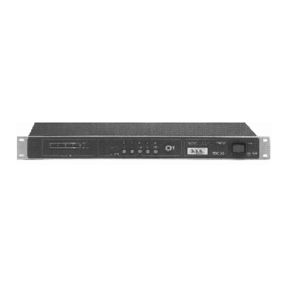
SDC20 STEREO DIGITAL CODER DESCRIPTION 1.1 EXTERNAL DESCRIPTION The SDC20 is contained in 19" 1U rack. This stereo digital coder is engineered for high performance stereo FM broadcasting. It's an equipment that integrates in a cheap model, but without quality compromises, all technical characteristics of the expansive Coders. -
Page 10: Technical Specification
SDC20 Stereo Digital Coder TABLE A TECHNICAL SPECIFICATION AUDIO INPUT (L & R) Input Level Adjustable from 0 to 12 dB Input Sensitivity 194 mVrms (-12 dBm) Input Impedance > 6 Kohm (balanced) Frequency Response from 20 Hz to 15 KHz... -
Page 11: Environmental Specifications
SDC20 Stereo Digital Coder TABLE B DIMENSIONAL AND ENVIRONMENTAL SPECIFICATIONS Operating Temperature -10°C to +50°C Humidity 95% Max, Non Condensing Weight 3.2 Kg (7 Lbs) Panel Size 483 mm (19") W mm (1.7") H 164 mm (6.45") D R.V.R. Elettronica S.r.l. (Bo) - Page 12 SDC20 Stereo Digital Coder FRONT PANEL (FIG.1) LEFT Left channel peak level meter by "Led Diode Bar" RIGHT Right channel peak level meter by "Led Diode Bar" PREEMPHASIS Pre-emphasis ON/OFF selector Left channel ON/OFF selector L=R / L=-R Channels phase selector...
- Page 13 SDC20 Stereo Digital Coder FIG.1 R.V.R. Elettronica S.r.l. (Bo) Pag. 13...
- Page 14 SDC20 Stereo Digital Coder REAR PANEL (FIG.2) XLR VERSION A.C. IN A.C. Line inlet MPX output channel connector (XLR male) MPX LEV MPX channel level selector RDS input channel (XLR female) SCA input channel (XLR female) LEFT LEFT input channel (XLR female)
- Page 15 SDC20 Stereo Digital Coder FIG.2 (XLR VERSION) R.V.R. Elettronica S.r.l. (Bo) Pag. 15...
- Page 16 SDC20 Stereo Digital Coder REAR PANEL (FIG.3) SOCKET VERSION A.C. IN A.C. Line inlet MPX output channel connector (Socket) MPX LEV MPX channel level selector RDS input channel (Socket) SCA input channel (Socket) LEFT LEFT input channel (Socket) LEFT LEV...
- Page 17 SDC20 Stereo Digital Coder FIG.3 (SOCKET VERSION) R.V.R. Elettronica S.r.l. (Bo) Pag. 17...
-
Page 18: Electrical Description
SDC20 Stereo Digital Coder S E C T I O N 2 ELECTRICAL DESCRIPTION 2.1 PANEL CARD This card is fixed on the left side of the front panel (1 Fig.4). The Panel card allows to display the Left and Right input signals level through a level meter on a scale from -20 dBm to + 15 dBm. -
Page 19: Installation Procedures
Verify that SDC20 coder is switch off. Connect the output connector of the mixer or of the last transmitter to R and L input connectors. The SDC20 coder input is balanced and can be of XLR type or socket type. Respect pins position showed in technical specifications of the connectors (Fig.5). - Page 20 NOTE: However the tuner used for the adjustments can be of good quality, the performances as separation of this equipment and of all transmitting system, improbably can be compared with SDC20 ones, therefore the results don't reflect quantitatively SDC20 characteristics.
- Page 21 SDC20 Stereo Digital Coder TOP VIEW DESCRIPTION (FIG.4) Panel card Main card Power switch Mains voltage inlet Mains voltage transformer Voltage switch 117 V - 230 V R.V.R. Elettronica S.r.l. (Bo) Pag. 21...
- Page 22 SDC20 Stereo Digital Coder TOP VIEW (FIG.4) R.V.R. Elettronica S.r.l. (Bo) Pag. 22...
- Page 23 SDC20 Stereo Digital Coder L & R INPUTS 1 - Ground 2 - Inphase (+) 3 - Return (-) With unbalanced signals ground terminal Return (3) connecting to terminal Ground (1). MPX OUTPUT 1 - Ground 2 - Output 3 - Ground RDS &...
- Page 24 SDC20 Stereo Digital Coder BALANCED INPUTS CONNECTION (FIG.6) STEREO CODER SDC20 CABLE END 1st Case 2nd Case XLR CABLE XLR CABLE L & R L & R CABLE END OTHER EQUIPMENT NOTE: In case of hum noise presence, disconnect the braide wire on connectors both of right channel and left channel of the XLR cable end connected on Stereo Coder (1st Case).
- Page 25 SDC20 Stereo Digital Coder APPENDIX A CIRCUIT DIAGRAMS, LAYOUTS AND BILLS OF MATERIAL This section contains circuit diagrams, layouts and bills of material of the modules which composing the equipment. For more information about each module see as reference Section 2.
- Page 26 SDC20 Stereo Digital Coder MAIN CARD Circuit Diagram Sheet 1 of 2 Pag. 27 Bill of Materials Sheet 1 of 2 Pag. 28 Circuit Diagram Sheet 2 of 2 Pag. 30 Bill of Materials Sheet 2 of 2 Pag. 31 Component Layout Pag.
- Page 27 SDC20 Stereo Digital Coder R.V.R. Elettronica S.r.l. (Bo) Pag. 27...
- Page 28 SDC20 Stereo Digital Coder MAIN CARD SDC20 Bill Of Materials Page Item Quantity Reference Part Description Part Order Code ________________________________________________________________________________________________ R12,R25 750 1% RESISTOR 1/4W 1% RSM1/4FH0750 R4,R11, 4K64 1% RESISTOR 1/4W 1% RSM1/4FK4,64 R18,R24 R6,R20 7K5 1% RESISTOR 1/4W 1%...
- Page 29 SDC20 Stereo Digital Coder MAIN CARD SDC20 Bill Of Materials Page Item Quantity Reference Part Description Part Order Code ________________________________________________________________________________________________ J10,J11 MORS.CS 2 MORS. C.S. 2 CONT MORSKB02PPO J4,J5 MORS.CS 4 MORS. C.S. 4 CONT. MORSKB04PPO J7,J8 MORS.CS 6 MORS. C.S. 6 CONT.
- Page 30 SDC20 Stereo Digital Coder R.V.R. Elettronica S.r.l. (Bo) Pag. 30...
- Page 31 SDC20 Stereo Digital Coder MAIN CARD SDC20 Bill Of Materials Page Item Quantity Reference Part Description Part Order Code ________________________________________________________________________________________________ RESISTOR 1/4W 5% RSC1/4JH0047 RESISTOR 1/4W 5% RSC1/4JH0100 R29,R33 200 1% RESISTOR 1/4W 1% RSC1/4FH0200 RESISTOR 1/4W 5% RSC1/4JH0330 R39,R45...
- Page 32 SDC20 Stereo Digital Coder MAIN CARD SDC20 Bill Of Materials Page Item Quantity Reference Part Description Part Order Code ________________________________________________________________________________________________ M10K TRIMMER MULTIGIRI RVTMULAK0010 POT50KX2 DOUBLE POTENT. 50K RVP0650K CERAMIC CAPACITOR NP0 CKM8,2BJ600C 27PF CERAMIC CAPACITOR NP0 CKM270BJ600C C19,C21, 47PF...
- Page 33 SDC20 Stereo Digital Coder MAIN CARD SDC20 Bill Of Materials Page Item Quantity Reference Part Description Part Order Code ________________________________________________________________________________________________ IC14 LF347N QUAD JFET IN.OP.AMP. CILLF347N LF353 DOUBLE OP. AMP. CILLF353 IC5,IC6, LF356 JPFET IN.OP.AMPLIFIER CILLF356 IC11 IC13,IC15 4015 SHIFT REGISTER...
- Page 34 SDC20 Stereo Digital Coder R.V.R. Elettronica S.r.l. (Bo) Pag. 34...
-
Page 35: Panel Card
SDC20 Stereo Digital Coder PANEL CARD Circuit Diagram Pag. 35 Bill of Materials Pag. 37 Component Layout Pag. 38 R.V.R. Elettronica S.r.l. (Bo) Pag. 35... - Page 36 SDC20 Stereo Digital Coder R.V.R. Elettronica S.r.l. (Bo) Pag. 36...
- Page 37 SDC20 Stereo Digital Coder SDC20 PANEL CARD Bill Of Materials Page Item Quantity Reference Part Description Part Order Code ________________________________________________________________________________________________ RESISTOR 1/4W 5% RSC1/4JK01,5 RESISTOR 1/4W 5% RSC1/4JK04,7 RESISTOR 1/4W 5% RSC1/4JK08,2 R2,R3,R6,R8 47K RESISTOR 1/4W 5% RSC1/4JK0047 R1,R5 RESISTOR 1/4W 5%...
- Page 38 SDC20 Stereo Digital Coder R.V.R. Elettronica S.r.l. (Bo) Pag. 38...
- Page 39 SDC20 Stereo Digital Coder LIMITER CARD (OPTIONAL) Circuit Diagram Pag. 40 Bill of Materials Pag. 41 Component Layout Pag. 42 R.V.R. Elettronica S.r.l. (Bo) Pag. 39...
- Page 40 SDC20 Stereo Digital Coder R.V.R. Elettronica S.r.l. (Bo) Pag. 40...
- Page 41 SDC20 Stereo Digital Coder SDC20 LIMITER CARD Bill Of Materials Page Item Quantity Reference Part Description Part Order Code ________________________________________________________________________________________________ R18,R36 RESISTOR 1/4W 5% RSC1/4JH0100 R2,R20 499 1% RESISTOR 1/4W 1% RSM1/4FH0499 R8,R26 1K5 1% RESISTOR 1/4W 1% RSC1/4FK01,5 R3,R21...
- Page 42 SDC20 Stereo Digital Coder SDC20 LIMITER CARD Bill Of Materials Page Item Quantity Reference Part Description Part Order Code ________________________________________________________________________________________________ NE570 IC 2 COMPANDOR CILNE570 C9,C19 N.C. NOT CONNECTED R.V.R. Elettronica S.r.l. (Bo) Pag. 42...
- Page 43 SDC20 Stereo Digital Coder R.V.R. Elettronica S.r.l. (Bo) Pag. 43...
- Page 44 SDC20 Stereo Digital Coder © Copyright 1994 Second Edition - July '96 Created By D’Alessio D. R.V.R. Elettronica S.r.l. (Bo) Via del Fonditore 2/2c - 40138 - Bologna (Italy) N a t io n al : P h o n e 0 5 1 / 6 0 1 . 0 5 . 0 6 r . a . F a x 0 5 1 / 6 0 1 . 1 1 . 0 4 I n t er na ti on a l : P h o n e + 3 9 - 5 1 - 6 0 1 .0 5.
Need help?
Do you have a question about the SDC20 and is the answer not in the manual?
Questions and answers