Table of Contents
Advertisement
Quick Links
Advertisement
Table of Contents

Subscribe to Our Youtube Channel
Related Manuals for R.V.R. Elettronica PJ10KPS-CA


Summary of Contents for R.V.R. Elettronica PJ10KPS-CA
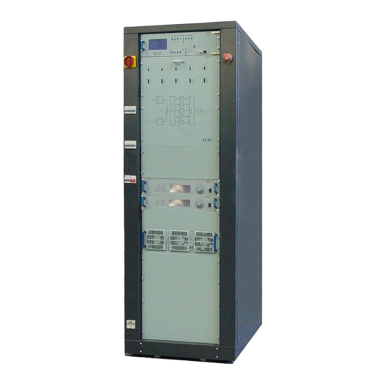
- Page 1 PJ10KPS-CA User & Technical Manual Rev. 2.1...
- Page 2 EC Declaration of conformity R.V.R. Elettronica S.p.A. declares that this transmitter is in conformity to the essential requi- rements and to other relevant regulations settled by the 1999/5/CE directive. Validity of the EC declaration of conformity. WARNING: the conformity of this product is not valid if the product is used in conditions not authorized by R.V.R.
- Page 3 Waste Electrical or Electronic Equipment (WEEE) This symbol indicates that you should not discard waste electrical or electro- nic equipment (WEEE) in the trash. For proper disposal, contact your local recycling/reuse or hazardous waste center. CAUTION Do discard waste electrical or electronic equipment (WEEE) in the trash. For proper disposal, contact your local recycling/reuse or hazardous waste center.
-
Page 4: Table Of Contents
PJ10KPS-CA Index Introduction..................Warranty....................First Aid....................Treatment of electrical shocks............. 3.1.1 If the victim is not responsive.............. 3.1.2 If victim is responsive................Treatment of electrical Burns.............. 3.2.1 Extensive burned and broken skin............3.2.2 Less severe burns................General Description................Composition..................Technical specifications.............. - Page 5 6.6.2.1 Splitter board trimmers............... 6.6.3 Directional coupler (SL042MT1001)........... 6.6.4 Combiner (PF1HC510KWPJ-158)............Emergency CCU Board (SLCCUEMPJ5K1)........6.7.1 Installation emergency CCU Board............ Services supply................... PJ10KPS-CA Ventilation..............6.10 Input socket..................6.11 Dummy load..................6.11.1 Absorber misure board (SLADKDIPK5K2)......... 6.11.1.1 Settings....................6.11.2 Absorber measure (SLPWRSEBHC52)..........
- Page 6 PJ10KPS-CA 8.6.3 Automatic changeover................ 8.6.4 Phase from ON to OFF............... 8.6.5 Start-up with exciters in automatic mode..........8.6.6 Audio alarm..................8.6.7 Protection and alarms................. User & Technical Manual...
-
Page 7: Introduction
PJ10KPS-CA 1. Introduction This manual describes the PJ10KPS-CA, a solid-state RF amplifier designed for frequency modulation sound broadcasting, manufactured by R.V.R. Elettronica S.p.A..A control system for the exciters is built into the machine so that in order to have a system with redundant exci- ters, all that needs to be done is to include two exciters in the transmitter such as, for exam- ple, the PTX30LCD exciters made by R.V.R. -
Page 8: Warranty
Very often installing errors are discovered by dealers. If your dealer cannot help you, contact R.V.R. Elettronica and explain the problem. If it is decided to return the unit to the factory, R.V.R. Elettronica will mail you a regular authori- zation with all the necessary instructions to send back the goods. - Page 9 PJ10KPS-CA Replacement and warranty parts may be ordered from the following address. Be sure to inclu- de the equipment model and serial number as well as part description and part number. R.V.R. Elettronica SpA Via del Fonditore, 2/2c 40138 BOLOGNA ITALY Tel.
-
Page 10: First Aid
PJ10KPS-CA 3. First Aid The personnel employed in the installation, use and maintenance of the device, shall be familiar with theory and practice of first aid.. Treatment of electrical shocks 3.1.1 If the victim is not responsive Follow the A-B-C’s of basic life support •... -
Page 11: If Victim Is Responsive
PJ10KPS-CA 3.1.2 If victim is responsive • Keep them warm • Keep them as quiet as possible • Loosen their clothing (a reclining position is recommended) • Call for medical help as soon as possible Treatment of electrical Burns 3.2.1 Extensive burned and broken skin •... -
Page 12: General Description
MOSFET as active components in the FM amplifying modules. This chapter briefly describes the machine’s main features. Composition The PJ10KPS-CA transmitter is made up of modules inserted in a 19” rack. The main appara- tuses are: • 5 RF amplifier modules at 2.2 kW nominal •... -
Page 13: Technical Specifications
PJ10KPS-CA The amplifier is supplied complete with all its parts, not really "modules", essential for its operation such as the fans for dissipating the heat generated by the machine inside the room and all the accessories for the electrical and RF wiring. As a rule, the amplifier is supplied as a complete transmitter therefore the two FM exciters that it manages will be provided and connected (a service exciter and a spare exciter). -
Page 14: Options
PJ10KPS-CA Typical power consumption of the machine: Transmitter Phase Current Phase Current Phase Current Neutral Current Power (KW) ) Amp. ) Amp. ) Amp. ) Amp. 12.3 10.9 14.2 11.8 11.9 16.1 12.9 14.3 18.1 13.8 16.7 20.1 14.9 19.3 21.6... -
Page 15: Opertaing Principles
220 V RS485 Figure 4-1 Block diagram of PJ10KPS-CA The RF signals generated by two exciters (in the redundant configuration) are first attenuated by 6 dB to improve the uncoupling among the stages and then connected to a coaxial relay commanded by the control unit. - Page 16 PJ10KPS-CA The system contains five RF sub-amplifier modules each of which is capable of supplying a maximum of 2.2 kW RF. Each RF sub-amplifier module incorporate a PFC (Power Factor Corrector) power supply that provides the utmost power efficiency for enhanced energy savings and environmental protection.
- Page 17 PJ10KPS-CA Figure 4-3 Internal view of module RF sub-amplifier User & Technical Manual...
-
Page 18: Datasheet Of Mrf6Vp11Khr5
PJ10KPS-CA Datasheet of MRF6VP11KHR5 ... - Page 19 PJ10KPS-CA ° ...
- Page 20 PJ10KPS-CA ° ° ° ± °...
- Page 21 PJ10KPS-CA η ...
- Page 22 PJ10KPS-CA Ω ...
- Page 23 PJ10KPS-CA User & Technical Manual ...
- Page 24 PJ10KPS-CA User & Technical Manual ...
-
Page 25: Control Unit (Cu)
PJ10KPS-CA 5. Control unit (CU) The operator controls and checks the status of the PJ10KPS-CA by means of the control unit (CU). Two control groups are present on this unit: • LCD and scroll buttons • Buttons, selector switches and LEDs... -
Page 26: Lcd Display
PJ10KPS-CA LCD Display The operator uses the control software of the transmitter by means of a series of menus that are displayed on the LCD. Four specific keys are provided for scrolling through the menus, performing the settings and giving the commands:... -
Page 27: Overall Status Menù
PJ10KPS-CA 5.1.1 Overall Status Menu This menu includes only indications, therefore the user cannot insert any input in its different lines.(Figure 5-2). Menù Line Description Timer (when Indication of the start and stop times of the automatic power enabled) reduction feature - see “Settings” menù... -
Page 28: Select Menù
Setting of the parameters (i.e. Power levels) Exciters Parameters of the exciters (i.e. output power, on air exciter) Info Information concerning the configuration of the PJ10KPS-CA Release Information concerning the hardware and software versions of the modules composing the unit... -
Page 29: Power Supply Menù
“Stand by” output line status from the control unit Total Eff Total efficiency of the machine Figure 5-4 5.1.4 Power supply menu informative menu of PJ10KPS-CA of the machine (Figure 5-5). Menu Line Description Bus Fan Supply voltage of the fans input Room T... -
Page 30: Combiner Menù
PJ10KPS-CA Figure 5-5 * The threephase control and the relative fuses are found on electromechanical section. 5.1.5 R.F. Combiner menu This menu contains the information related to the RF part of the complete transmitter. (Figure 5-6). Menu Line Description Overall emitted RF power of the transmitter... -
Page 31: Units Menù
PJ10KPS-CA Figure 5-6 5.1.6 R.F. Units menu Information menu showing the status of the RF power amplifier modules. (Figure 5-8). It is composed of 5 screens, one for each module, that can be scrolled using the arrow buttons. Menu Line... -
Page 32: Alarms Menù
PJ10KPS-CA 5.1.7 Alarms menu This screen describes all the registered events which are relevant to determine the pro- bable causes of any dysfunction. The screen is composed of a variable number of pages (up to 10) in function of the number of events occurred (Figure 5-9). The last events in chronological order are shown in the first page and so on. -
Page 33: Settings Menù
Description Nominal Pwr Setting of the level of nominal power, expressed as a percentage of the maximum power level. This is the level that the PJ10KPS-CA must reach when the Power Nominal button is pressed, except in case of dysfunction... -
Page 34: Exciters Menù
PJ10KPS-CA Figure 5-11 5.1.10 Exciters menu This menu is used to configure the settings of the exciters (Figure 5-12). Menu Line Description Main Exc Output power of the exciter currently on air Stdby Exc Output power of the exciter currently on the internal dummy load Main Exciter Visualization of the “on air”... -
Page 35: Info Menù
PJ10KPS-CA 5.1.11 Info menu This screen informs the user about the configuration of the transmitter. (Figure 5-13). Menu Line Description S.N. Serial number of the transmitter Talk Addr. Address of the RS485 port of the transmitter,it must be obligatorily 3... - Page 36 PJ10KPS-CA Menu Line Description S.N. -1 Year of production of the module S.N. -2 Serial number of the module Figure 5-14 Figure 5-14a User & Technical Manual...
-
Page 37: Modem Menù
PJ10KPS-CA 5.1.13 Modem menu This screen informs the user about the configuration of the optional telemetry GSM (Fi- gure 5-15). The parameters on this screen can be displayed only if the selector switch on the CU is located at a REMOTE location, if it is placed in the LOCAL screen appears as in Figure 5-15a. -
Page 38: Buttons, Selector Switches And Leds
PJ10KPS-CA Buttons, selector switches and LEDs The typical machine-control operations are performed using the buttons of the control unit’s panel. Specific LEDs correspond to each button and selector switch for indicating the machine’s status.(Figure 5-16). Figure 5-16 The functions performed by the controls are as follows:... - Page 39 PJ10KPS-CA LOC/REM Selector switch for setting the transmitter in remote or local mode. In local mode the buttons and the controls via the me- nus are active. In remote mode the buttons and the controls via the menus are inhibited and the commands may be given only remotely via the parallel interface or via the remote con- trol software.
-
Page 40: Alarms
PJ10KPS-CA Alarms The menu Alarms of the control unit reports all the events connected to possible malfunctioning of the equipment or due to external causes. Each registration contains the reference to the concerned module, the kind of event and its date and hour. - Page 41 PJ10KPS-CA Combiner -Fwd forward power above its limit -Rfl reflected power above its limit -O.dvr In overdrive (main exciter) -O.dvr Ld Too much power dissipated on the internal dummy load (stand by exciter) -Unbal Unbalancement power above its limit -Rej.l.T...
-
Page 42: Wiring Diagrams
PJ10KPS-CA Wiring diagrams GENERAL VIEW Control Unit RF module Emergency button Main switch Breaker module 1 and 2 Breaker module 3 and 4 Breaker module Electromechanical 5 and Services section (sliding) Exciter 1 Exciter 2 Dummy load Shuko socket with fuse... - Page 43 PJ10KPS-CA Splitter Module box Combiner Power supply board tray fans Threephase transformer Switching transformer for tray fans User & Technical Manual...
- Page 44 PJ10KPS-CA GSM telemetry Input socket RF output (opz.) Parallel interface Power supply (opz.) input Services supply IF YOU DO NOT ENTER THE BRIDGE, THE TRANSMITTER WILL NOT TURN ON (SEE CAP. 6.8) Slot for the passage of cables Air hole output Ø=300mm...
-
Page 45: Control Unit (Cu)
PJ10KPS-CA Control unit (CU) CCU board (SLCCUPJ5KM2) CCU motherboard (SLCCU1PJ5KM2) User & Technical Manual... -
Page 46: Ccu Board (Slccupj5Km2)
PJ10KPS-CA 6.1.1 CCU board (SLCCUPJ5KM2) User & Technical Manual... - Page 47 PJ10KPS-CA +12V R S T U 2 D U 2 B C S D 8 7 W -20K + 5 V B A V99B R D _ D IS +12V C 2 C M 2 2 p F C M 1 0 pF...
- Page 48 PJ10KPS-CA R 3 5 U 1 3 E U 1 4 D T L P 5 2 1-4 R 3 7 O N _ R EM R 3 6 R 3 8 P B _ ON U 1 7 A...
- Page 49 PJ10KPS-CA +12V C 6 1 R 1 2 3 U 2 2 A U L N 2 0 0 4 A +12V R 1 2 4 1 0 0 R U 2 6 E R 1 2 8 R 1 2 9...
- Page 50 PJ10KPS-CA User & Technical Manual...
-
Page 51: Ccu Motherboard (Slccu1Pj5Km2)
PJ10KPS-CA 6.1.2 CCU motherboard (SLCCU1PJ5KM2) User & Technical Manual... - Page 52 PJ10KPS-CA M U T _ C L O A D+ I N P + M U T E 1 _OC M A I N _ E X CT_OC P B OK_TST O N _ T ST D A C 1 _ O U T...
- Page 53 PJ10KPS-CA User & Technical Manual...
-
Page 54: Settings
PJ10KPS-CA 6.1.3 Settings PTX-LCD Leaving the jumpers as shown in the figure, the audio alarm is active, 13.7 Scheda pannello that is, when the audio is no longer present at the exciter, at the time of on air, the system automatically switches on the other exciter. - Page 55 PJ10KPS-CA Meaning Jump JP8 with 8-bit CPU Meaning Jump JP8 with 16-bit CPU AC 18V Power supply pinout AC 18V - RELE + RELE User & Technical Manual...
-
Page 56: Rf Module
PJ10KPS-CA RF module Note 1 Note 2 (below 5) (below 5) Internal view User & Technical Manual... - Page 57 PJ10KPS-CA N° Description Code Chapter 3-way combiner CSCMBMOD2KPJ 6.2.1 Pallet mosfet KKFIN237C 6.2.2 Temperature probe SLSNDTMPJ5K 6.2.3 Splitter CSSPLTEX1KL1 6.2.4 Fuses board CSFU0359R1 6.2.5 Driver board SLDRVRFPJ5M 6.2.6 Db-15 connector filtered SLDB15FFILF1 Pass through board CSFI0368R1 6.2.7 Db-9 connector filtered...
- Page 58 PJ10KPS-CA Function Description PWR ADJ Trimmer adjustment of the output power of a single mo- dule, this control operates by varying the VPA pallet mo- sfet PHASE ADJ ip-switch for the regulation of the phase of the RF signal generated. The phase of each RF module could be modi- fied independently to steps of 1.6°...
- Page 59 PJ10KPS-CA DB-37 connector RF input connector (“N” type) Power supply connector Pin 1= Neutral Pin 2= NC Pin 3= NC Pin 4= Phase Pin 5= GND Ground connector RF output connector (7/16” EIA) Rear view User & Technical Manual...
-
Page 60: 3-Way Combiner (Cscmbmod2Kpj)
PJ10KPS-CA 6.2.1 3-way combiner (CSCMBMOD2KPJ) User & Technical Manual... -
Page 61: Pallet Mosfet (Kkfin237C)
PJ10KPS-CA 6.2.2 Pallet mosfet (KKFIN237C) User & Technical Manual... - Page 62 PJ10KPS-CA PAD4 PAD4 +50V Input +50V Input Bias input Bias input PAD1 PAD1 470n 470n FIX9 FIX9 R9 1K R9 1K FIX55 FIX55 BIAS Input BIAS Input R10 1K R10 1K RV1 1K RV1 1K R11 NC R11 NC 470p...
- Page 63 PJ10KPS-CA PALLET FM 800 W Revised: 20/01/2012 SL237RF1001 Revision: 1.1 Exciter High Efficienty Luca Gasperini Item Quantity Reference Part {description} COAX1 RG178 60mm in binocolo ferrite Cavo RG178 60mm calza/calza in binocolo ferrite (73mm tot.) COAX2, COAX3 Cavo RG316/25 - 80mm Cavo RG316/25 80mm calza/calza (91mm tot.)
-
Page 64: Temperature Probe
PJ10KPS-CA 6.2.3 Temperature probe (SLSNDTMPJ5K) User & Technical Manual... -
Page 65: Spliter (Csspltex1Kl1)
PJ10KPS-CA 6.2.4 Splitter (CSSPLTEX1KL1) User & Technical Manual... -
Page 66: Fuse Board (Csfu0359R1)
PJ10KPS-CA 6.2.5 Fuses board (CSFU0359R1) User & Technical Manual... - Page 67 PJ10KPS-CA User & Technical Manual...
- Page 68 PJ10KPS-CA Scheda Fusibili Revised: Wednesday, July 18, 2012 SLFU0359R01V01 Revision: 1.0 10KW Plugin\ RVR243 Item Quantity Reference Part Description Code ______________________________________________ 1 CN1 CN03PS Connettore 3 poli Mascon CNTMASM20PCS Spezzato 1 CS1 CSFU0359R1 Circuito stampato CSFU0359R1 11 C1,C2,C3,C4,C5,C6,C7,C8, 1nF/100V Cond. ceramico p 5mm...
-
Page 69: Driver Board (Sldrvrfpj5M)
PJ10KPS-CA 6.2.6 Driver board (SLDRVRFPJ5M) User & Technical Manual... - Page 70 PJ10KPS-CA User & Technical Manual...
- Page 71 PJ10KPS-CA DRIVER2KW.BOM RF Driver 2KW Unit Revised: Thursday, April 22, 2013 CSDRVRFPJ5KM Revision: 1.1 PJ5000MC PJ5000MC_Code /Driver2KW.dsn Mauro Ucelli 07/06/01 Bill Of Materials May 2,2002 17:52:38 Page1 Item Quantity Reference Part ______________________________________________ C1,C5,C17,C25,C27,C39, 680p_HQ ;(Condensarore chip HQ 680pF) C43,C44 C11,C2 100n_63V ;(Condensatore Multistrato 100nF...
-
Page 72: Pass Throught Board (Csfi0368R1)
PJ10KPS-CA 6.2.7 Pass through board (CSFI0368R1) User & Technical Manual... - Page 73 PJ10KPS-CA User & Technical Manual...
- Page 74 PJ10KPS-CA Scheda passaparete Revised: Wednesday, July 11, 2012 SLFI0368R01V01 Revision: Amplifiucatore 10KW Plugin RVR243 Item Quantity Reference Part Description Code ______________________________________________ 1 CS1 CSFI0368R1 Circuito stampato CSFI0368R1 8 C1,C2,C3,C4,C5,C6,C7,C8 680pF Cond. SMD 1212 HQ CHQ681JA101 6 FIX1,FIX2,FIX3,FIX4,FIX5, FIX35 Foro fissaggio 3.5mm...
-
Page 75: Shunt Board (Csmt0367R1)
PJ10KPS-CA 6.2.8 Shunt board (CSMT0367R1) User & Technical Manual... - Page 76 PJ10KPS-CA User & Technical Manual...
- Page 77 PJ10KPS-CA Scheda Shunt Misura IPA Revised: Wednesday, July 11, 2012 SLMT0367R01V01 Revision: 1.0 10KW FM Plugin RVR243 Tommasi A. Bill Of Materials Page1 July 11,2012 12:29:25 Item Quantity Reference Part Description Code ______________________________________________ 1 CS1 CSMT0367R1 Circuito stampato CSMT0367R1 8 FIX1,FIX2,FIX3,FIX4,FIX5, FIX45 Foro fissaggio 4.5mm...
-
Page 78: Bias Board (Csbi0358R1)
PJ10KPS-CA 6.2.9 Bias board (SLBI0358R01V01) User & Technical Manual... - Page 79 PJ10KPS-CA IN_GFB_S V_DRV IN_CH0 IN_IN1 BIAS_D FIX14 FIX14 FIX15 FIX15 PWR_DIR UNBAL IN_CH1 +12V FIX35 FIX35 FIX35 FIX35 PWR_RFL IN IN2 +12V 1nF/100V 1nF/100V IN_CH2 IN_IN3 -12V PWR_INP FUSE_5040 -12V IN_CH3 I_PAL2 IN IN4 IN_CH4 1nF/100V 1nF/100V I_PAL3 IN IN5...
- Page 80 PJ10KPS-CA C115 100pF C115 100pF BC857 BC857 +12V -12V BAS32 BAS32 10K0 10K0 100nF 100nF TP10 TP10 22uF/16V 22uF/16V 4K70 4K70 4K99 4K99 TP05 TP05 OC_BIAS_OUT BAS32 BAS32 4K70 4K70 +12V +12V +12V +12V +12V TL072SMD TL072SMD BAS32 BAS32 Q13A...
- Page 81 PJ10KPS-CA 100uF/16V 100uF/16V 100uF/16V 100uF/16V V_DRV 51H0 51H0 51H0 51H0 51H0 51H0 V_DRV PFS520 PFS520 R79 0H047 R79 0H047 VDRV Z12V Z12V Z12V Z12V R161 NC R161 NC 10K0 10K0 10K0 10K0 10K0 10K0 10K0 10K0 10K0 10K0 10K0 10K0...
- Page 82 PJ10KPS-CA Adattatore CPU per sez. BIAS Revised: Wednesday, July 18, 2012 SLBI0358R01V01 Revision: 1.0 10KW Plugin amplifier RVR243 Item Quantity Reference Part Description Code ______________________________________________ 2 CN1,CN7 CN02PS Connettore 2 poli Mascon CNTMASM20PCS Spezzato 1 CN2 CN04PS Connettore 4 poli Mascon...
- Page 83 PJ10KPS-CA 1 JP4 CN40PD Conn.M.C.S.Dritto 40P CNTMCS40A 1 JP5 CN16PD Conn.M.C.S.Dritto 16P alette. CNTMCS16A 2 JP6,JP9 STM03S Strip maschio 3 pin CNTSTM40DDA Spezzata 1 JP7 CN10PD Connettore 10 poli Flat cs con alette CNTMCS10A 3 JP8,JP10,JP11 STF02S Strip femmina 2 pin...
- Page 84 PJ10KPS-CA 6 U1,U7,U8,U9,U10,U11 TL074 Quad Op. SMD SO14 CILTL074SMD 1 U2 LM7812 Stabilizzatore TO220 CIL7812P 1 U3 LM7912 Stabilizzatore TO220 CIL7912P 1 U4 Temperature sensor 1 U5 Dual Op. SMD SO8 1 U6 TL072SMD Dual Op. SMD SO8 CILTL072SMD 6 U12,U13,U14,U15,U16,U17 TL071/SO Single Op.
-
Page 85: Settings
PJ10KPS-CA 6.2.9.1 Settings User & Technical Manual... -
Page 86: Cpu Board (Cpupj2Kmc)
PJ10KPS-CA 6.2.10 CPU board (CPUPJ5KMC2) User & Technical Manual... - Page 87 PJ10KPS-CA User & Technical Manual...
- Page 88 PJ10KPS-CA User & Technical Manual...
- Page 89 PJ10KPS-CA User & Technical Manual...
- Page 90 PJ10KPS-CA User & Technical Manual...
- Page 91 PJ10KPS-CA Revised: Monday, July 01, 2013 JP6,JP7,JP8 STRIP 2 U5,U6,U7,U8 TL074 Revision: 1.1 OC1,OC2 TLP521-1 U10,U12,U14 40106 BC237 U11,U13 ULN2004A R1,R2,R3,R4,R5,R21,R22, 1K MC68HC908GP32-QFP R23,R24,R25,R41,R45,R46, 74HC273 R47,R59,R105,R108,R109, 74HC574 R118,R119 TLV5625 R6,R7,R8,R9,R10,R26,R27, 100R 74HC244 R28,R29,R30,R42,R54,R55, SN75176AP Bill Of Materials July 1,2013 11:30:32 Page1...
-
Page 92: Settings
6.2.10.1 Settings In the PJ10KPS-CA are present microcontrol boards, one for each 2.2 kW module, one for the control of the power supply and one for the control of the combiner. The boards are identical, but in each the trimmers have diverged meaning. In figure, “RFM” refers to the RF module, “PS” to the power supply and “CMB”... -
Page 93: Pfc (Kpfc154)
PJ10KPS-CA 6.2.11 PFC (KPFC154) User & Technical Manual... - Page 94 PJ10KPS-CA User & Technical Manual...
- Page 95 PJ10KPS-CA User & Technical Manual...
- Page 96 PJ10KPS-CA 9K76 330K CP.22uF CD470pF CP.22uF +15V CD.1UF CM1uF MOLEX 4 PUVLO CT1/25 20K0 470K 47K0 47K0 CP.22uF 330K0 CP.1uF 3106X-10K VAOUT CP1uF 4K99 +15V L4981A GDRV CD470pF CD10KpF 13K3 BYV27-200 MOUT 6V8-0.5W CD.1uF IRFD9120 BYV27-200 9K76 CD100pF 22/25 OUTA...
- Page 97 PJ10KPS-CA ...
- Page 98 PJ10KPS-CA MKP 0.047uF 400 MKP 0.047uF 400 100pF-1kV 100pF-1kV 100R-2W 100R-2W T94-2 6uH T94-2 6uH TPFC5060 HFA50PAC HFA50PAC 13uH 13uH 0,2mH 0,2mH 20ETS08 20ETS08 STTA806D STTA806D MOLEX 4 MOLEX 4 5R6-2W 5R6-2W UF4006 UF4006 470uF-400 470uF-400 GBPC2508W GBPC2508W MKP2.2uF/400 MKP2.2uF/400...
- Page 99 PJ10KPS-CA ...
- Page 100 PJ10KPS-CA ...
- Page 101 PJ10KPS-CA ...
-
Page 102: Power Supply (Psl4280)
PJ10KPS-CA 6.2.12 Power supply (PSL4280) User & Technical Manual... - Page 103 PJ10KPS-CA User & Technical Manual...
- Page 104 PJ10KPS-CA 5V-REF C122 +13V 59K0 SMD .1uF SMD R165 1K5 SMD VSENSE +13V VGOOD +13V +13V VOLTAGE TO CURRENTE 10K SMD 2N7002 SMD 1uF SMD .1uF SMD MODE VREF NTC_D NTC_D .1uF SMD CS_OUT LL4148 10K SMD R172 40K2 SMD...
- Page 105 PJ10KPS-CA 5V-REF .1uF SMD 100R SMD 10K SMD 1uF SMD LL4148 LL4148 LL4148 CD40106 SOIC .1uF SMD 6K65 SMD VSENSE BCR135 VSENSE 10uF SMD 56K SMD VGOOD QA461-14.7456MHz VGOOD R176 C66 27pF SMD CC_IN 10R SMD CC_IN 10K SMD CS_OUT...
- Page 106 PJ10KPS-CA GND_SOUT OUT MAX 600mA @ 13V => 500mA@24V 1N4004 SMD ZLH220/35 CP1KP-100V .1uF SMD GND_SOUT GND_SOUT BL02 R111 C100 .1uF SMD .1uF SMD 1K 1/4W PX470/35 N.B. Stellare la +13V_D 100v 1N4004 SMD +13V_D .1uF SMD .1uF SMD +13V_D...
- Page 107 PJ10KPS-CA PSL4280 PWM CONTROLLER Revised: 1uF SMD Friday, May 24, 2013 1uF SMD PSL4280CNT Revision: 1 1uF SMD 1uF SMD 1uF SMD 1uF SMD 1uF SMD 1uF SMD 1UF SMD 1uF SMD Bill Of Materials June C106 1uF SMD 27,2013...
- Page 108 PJ10KPS-CA ZLH220/35 LUNENO ZLH220/35 2N7002 SMD CE100/25 2N7002 SMD C100 PX470/35 BCR135 C109 CP .47uF BCR135 ROSSO 0805 BCR135 ROSSO 0805 BCR135 ROSSO 0805 BCR135 ROSSO 0805 BCR135 5V1-0.5W SMD IRLL110BF 5V1-0.5W SMD 1K5 SMD DZ10 5V1-0.5W SMD 1K5 SMD...
- Page 109 PJ10KPS-CA R122 5K60 SMD R148 4K7 SMD 68K SMD 5K6 SMD 68K SMD 56K SMD 22K SMD 56K SMD 22K SMD 56K SMD 22K SMD 56K SMD 6K8 SMD R138 56K SMD 6K8 SMD R176 56K SMD 6K8 SMD 2K2 SMD...
- Page 110 PJ10KPS-CA User & Technical Manual...
- Page 111 PJ10KPS-CA +15V CM.1uF SMD CM1uF SMD +15V TC4422 BYM13-40 SMD GATE_B 22R SMD 10R-2W CM1uF SMD 22R SMD CM1uF 5R6 SMD CM1uF +400VDC BYM13-40 SMD Gate +15V SourceB 16V-1W SMD 16V-1W SMD GateB +400VDC CM.1uF SMD CM1uF SMD +400VDC +15V...
- Page 112 PJ10KPS-CA DRIVER PSL4280 Revised: Tuesday, 10R-2W April 30, 2013 5R6 SMD CS4280_DRV.DSN Revision: 1 5R6 SMD 5R6 SMD 5R6 SMD 22R SMD 22R SMD 22R SMD 22R SMD 22R SMD Bill Of Materials June 22R SMD 27,2013 7:58:16 Page1 T6-GDRV...
- Page 113 PJ10KPS-CA User & Technical Manual...
- Page 114 PJ10KPS-CA User & Technical Manual...
- Page 115 PJ10KPS-CA SEZIONE DI POTENZA INGRESSO Revised: Thursday, May 16, 2013 PSL4280_PWRIN.DSN Revision: 1 Bill Of Materials June 27,2013 7:58:32 Page1 Item Quantity Reference Part ______________________________________________ PE-51718 Y2K2pF Y2K2pF 470/400 CP2.2/400 CP2.2/400 CD10KpF-1KV CD10KpF-1KV CP.1uF-400'V 1KpF 1KpF 1KpF 1KpF STTH8R06D-RHRP860 STTH8R06D-RHRP860...
- Page 116 PJ10KPS-CA User & Technical Manual...
- Page 117 PJ10KPS-CA User & Technical Manual...
- Page 118 PJ10KPS-CA SEZIONE DI POTENZA USCITA Revised: Monday, June 10, 2013 CS4280_PWROUT.DSN Revision: 1 Bill Of Materials June 27,2013 7:58:47 Page1 Item Quantity Reference Part ______________________________________________ LA 100-P/SP13 HTP100-S CP.1uF CP.1uF CP.1uF CP.1uF CP.1uF CP.1uF CP.1uF CP.1uF CP.1uF CP.1uF CP.1uF CP.1uF CP.1uF...
- Page 119 PJ10KPS-CA User & Technical Manual...
- Page 120 PJ10KPS-CA User & Technical Manual...
- Page 121 PJ10KPS-CA CONNECT TA NTC INPUT Revised: Monday, June 10, 2013 CSPSL4280_TA.DSN Revision: 1 Bill Of Materials June 27,2013 7:57:43 Page1 Item Quantity Reference Part ______________________________________________ CM.1uF BYV27-200 MICS6 STRIP-6 90GR JUMP 2P 27R-2W 330R-1/4W 470R 560R-1/4W User & Technical Manual...
- Page 122 PJ10KPS-CA User & Technical Manual...
- Page 123 PJ10KPS-CA CONNECT TA NTC OUT Revised: Monday, June 10, 2013 CS4280CSOUR0.DSN Revision: 1 Bill Of Materials June 27,2013 7:58:00 Page1 Item Quantity Reference Part ______________________________________________ CM.1uF CM.1uF MICS6 STRIP7-90GR JUMP 2P 10R-1/4W User & Technical Manual...
- Page 124 PJ10KPS-CA User & Technical Manual...
- Page 125 PJ10KPS-CA SNUBBER DIODE OUT Revised: Monday, June 10, 2013 CS4280SNUBR0.DSN Revision: 1 Bill Of Materials June 27,2013 7:59:07 Page1 Item Quantity Reference Part ______________________________________________ CP1KpF-1KV FIX1 FIX45 FIX2 FIX45 3R3-2W 3R3-2W 3R3-2W User & Technical Manual...
-
Page 126: Directional Coupler (Csdclpfpj1Km)
PJ10KPS-CA 6.2.13 Directional coupler (CSDCLPFPJ1KM) Reflex Foward User & Technical Manual... - Page 127 PJ10KPS-CA User & Technical Manual...
- Page 128 PJ10KPS-CA Dir. Coupler Module 1KW Revised: Tuesday, February 26, 2002 Revision: 1.0 PJ5000MC PJ5000MC Testina1k Ucelli Mauro 24/10/2001 Bill Of Materials June 26,2002 11:00:00 Page1 Item Quantity Reference Part ______________________________________________ C5,C1 47p C2,C4,C6,C7 4n7 470n D2,D1 BAT83 RV2,RV1 200R R3,R1 100k...
-
Page 129: Low Pass Filter 1 (Cslpf1Mod2K)
PJ10KPS-CA 6.2.14 Low pass filter 1 (CSLPF1MOD2KW) User & Technical Manual... -
Page 130: Capacitor 1 (Csb1Lpfpj1Km)
PJ10KPS-CA 6.2.15 Capacitor 1 (CSB1LPFPJ1KM) 6.2.16 Card outlet connector (SLOUTRFPJ5K1) User & Technical Manual... -
Page 131: First Capacitance Low Pass Filter (Cslp03721)
PJ10KPS-CA 6.2.17 First capacitance low pass filter (CSLP0372R1) 6.2.18 Low pass filter 2 (CSLPF2MOD2KW) User & Technical Manual... -
Page 132: Electromechanical Section
PJ10KPS-CA Electromechanical section N° Description Code Chapter Relay interface board CSRLYCPROTVJ 6.3.3 Service transformer SLADPPSPJ5K2 6.3.4 P.S. combiner PF1ADPSPJ5KM CPUPJ5KMC 6.2.10 User & Technical Manual... - Page 133 PJ10KPS-CA User & Technical Manual...
-
Page 134: 220/380 V Wiring Diagram
PJ10KPS-CA 6.3.1 220/380 v wiring diagram User & Technical Manual... -
Page 135: Low Tension And Signal Wiring Diagram
PJ10KPS-CA 6.3.2 Low tension and signal wiring diagram User & Technical Manual... - Page 136 PJ10KPS-CA NOTE (1) User & Technical Manual...
- Page 137 PJ10KPS-CA NOTE (2) User & Technical Manual...
- Page 138 PJ10KPS-CA NOTE (3) User & Technical Manual...
- Page 139 PJ10KPS-CA NOTE (4) User & Technical Manual...
- Page 140 PJ10KPS-CA SWITCHING TRANFORMER FOR TRAY FANS R S P - 1 0 0 0 1000W Single Output Power Supply s e r i e s Mechanical Specification Case No. 952B Unit:mm 277.7 3-M4 L=6 34.5 Air flow SVR51 direction CN50...
-
Page 141: Relay Interface Board (Csrlycprotvj)
PJ10KPS-CA 6.3.3 Relay interface board (CSRLYCPROTVJ) User & Technical Manual... - Page 142 PJ10KPS-CA User & Technical Manual...
- Page 143 PJ10KPS-CA SLRLYCPROTVJ Bill Of Materials Page1 Item Q.ty Reference Part _____________________________________________________________________________ _______________ CN18 DB9-CS-M C1, C2, C3, C4, C5, C6, C7 CE10/25 DL1, DL2, DL3, DL4, DL5, DL6, DL7 LED D3V LED D3R D1, D2, D3, D4, D5, D6, D7, D8...
-
Page 144: Combiner Adapter (Sladpppspj5K2)
PJ10KPS-CA 6.3.4 P.S. combiner adapter (SLADPPSPJ5K2) +105° +105° User & Technical Manual... - Page 145 PJ10KPS-CA 1 N 4 1 48 +12V C D 1 K p F 1 N 4 1 48 +12V C D 1 K p F 1 N 4 1 4 8 +12V R 4 5 R 4 6 C N 6...
- Page 146 PJ10KPS-CA CSRLYCPROTVJ O C _ O U T 0 O C _ O U T 1 O C _ O U T 2 O C _ O U T 3 C _ F A N O C _ O U T 7 DISS.
- Page 147 PJ10KPS-CA SLADPPSPJ5KM2 R5,R9 RXE110 Bill Of Materials Page1 R6,R31,R38,R63,R67,R101, RXE020 R102,R117,R118,R121,R126 Item Q.ty Reference Part R7,R32,R39 5R6/2W ________________________________________________________________________________ R27,R12 ____________ R13,R24,R45,R46,R47,R64, R65,R66,R68,R69,R70,R86, DB9 FEM. R87,R88,R89,R103,R105, DB25 MASC R106,R119,R120 FLAT16 R15,R17,R18,R30,R48,R50, 100R CN4,CN5,CN7,CN9 DB9 MASC R52,R54,R55,R56,R57,R59, CN6,CN8 DB9 FEM R61,R71,R73,R74,R76,R78, CN10...
-
Page 148: P.s. Combiner Trimmer
6.3.4.1 P.S. combiner trimmer In the PJ10KPS-CA are present microcontrol boards, one for each 2.2 kW module, one for the control of the power supply and one for the control of the combiner. The boards are identical, but in each the trimmers have diverged meaning. In figure, “RFM” refers to the RF module, “PS” to the power supply and “CMB”... -
Page 149: Parallel Interface (Csintrempj5K)
PJ10KPS-CA Parallel interface (opz.)(CSINTREMPJ5K) A parallel-type interface is mounted on the top of the PJ10KPS-CA, in which the different signals are available through terminal blocks (Figure 6.4.1). This interface is connected to the CU from which it receives the different signals and to which the eventual commands are forwarded. - Page 150 Corresponds to the OFF button of the control unit JP4/4 EXT INH External inhibition jumper. It is a “N.C.” type jumper, which means that it must be active for the PJ10KPS-CA to work. Upon delivery, this terminal is closed to ground by a jumper. JP4/5 AUX INH Auxiliary external inhibition jumper.
- Page 151 Audio alarm of exciter 1. This input, when active, indica- EXC. 1 tes an alarm on exciter 1. If the PJ10KPS-CA is in automa- tic changeover modality, if the exciter 1 is on air and if this signal remains active for a time lag equivalent to the time setted in the Settings menu at line Exc.
- Page 152 PJ10KPS-CA JP22/2 I/O TX/RX - Bus RS 485 JP22/3 / LINE TRM Line termination for bus RS 485 JP22/4 / LINE TRM Line termination for bus RS 485 JP48/1 / Ground JP48/2 / Ground JP48/3 Out FWD PWR Forward power. Analogical output, 3.9V for 5000W...
- Page 153 The common contact of this output is RL3 (JP47/3). JP38/3 LOWER PO- Digital output, active when the PJ10KPS-CA is set for the lower power level. Common contact of this output is the (JP47/3). JP38/4...
- Page 154 PJ10KPS-CA User & Technical Manual...
- Page 155 PJ10KPS-CA J P 4 +12V C _ A U D _ A L A R M +12V +12V +12V M A I N S _ B U S J U M P E R 3 J U M P E R 3...
- Page 156 PJ10KPS-CA DAC5_OUT C _ R L 4 C _ R L 3 C _ R L 3 +12V +12V C 4 3 4 K 7 p F A C K _ R I S 1 R R 9 A R R 1 3 D...
- Page 157 PJ10KPS-CA SLINTREMPJ5KM Bill Of Materials Page1 Item Q.ty Reference Part _______________________________________________________________________________________ _____ C1,C45 47/25 C2,C3,C4,C5,C6,C7,C8,C9, 4K7pF C10,C11,C12,C13,C14,C15, C16,C17,C18,C19,C20,C21, C22,C23,C24,C25,C26,C27, C28,C29,C30,C31,C32,C33, C34,C35,C36,C37,C38,C39, C40,C41,C42,C43,C44,C46, C47,C48,C49,C50,C51,C52, C53,C54,C55,C56,C57,C58, C59,C60,C61,C62,C63,C64, C65,C66,C67,C68,C69,C70, C71,C72 DL1,DL2,DL3,DL4,DL5,DL6, D3-V DL7,DL8,DL9,DL10,DL11, DL12,DL13,DL14,DL15,DL16, DL17,DL18,DL19,DL20,DL21, DL22,DL23,DL24,DL25,DL26, DL27,DL28,DL29,DL30,DL31, DL32,DL33,DL34,DL35,DL36, DL37,DL38,DL39 DZ2,DZ1 12V-1W DZ4,DZ3 5V6-1W...
-
Page 158: Module Box
PJ10KPS-CA Module box N° Description Chapter RF module (N° 1 from left) Tray fans 6.5.1 RF module I/O 6.5.2 interface Presence module switch Power supply bo- 6.5.3 ard tray fans User & Technical Manual... -
Page 159: Tray Fans (Casvtlmpj10Kvc)
PJ10KPS-CA 6.5.1 Tray fans (CASVTLMPJ10KCV) FAN 80x80 48v POWER CONNECTOR ILME Pinout ilme male power supply Cable color Description + (48V DC) Purple Speed control Black - (0 V) Black - (0 V) User & Technical Manual... - Page 160 PJ10KPS-CA User & Technical Manual...
- Page 161 PJ10KPS-CA CSALVTL2KWPJA/CSALVTL2KWPJB - Bill of material Item Qty Reference Part Description Conn. Ilme 4 poli maschio + supporto 220 ohm Resistenza 1/4W 4,7 kohm Resistenza 1W Led verde Diodo led 5mm C1,C3,C5,C7,C9 100nF 60V Condensatore a disco C2,C4,C6,C8 1000uF 63V Condensatore elettr.
-
Page 162: Rf Module I/O Interface (Sliorfpj5Km2)
PJ10KPS-CA 6.5.2 RF module I/O interface (SLIORFPJ5KM2) User & Technical Manual... - Page 163 PJ10KPS-CA User & Technical Manual...
-
Page 164: Rf Module Address
PJ10KPS-CA CSIORFPJ5KM2 Bill Of Materials Page1 Item Q.ty Reference Part ________________________________________________________________________________ ____________ FIX1,FIX2,FIX3,FIX4 FIX35 HEADER HEADER R2,R1 RXE110 PTC_1 SW DIP-6 6.5.2.1 RF module address The address assigned to the module is mailed by a dip-switch on the interface board (SW1). -
Page 165: Power Supply Board Tray Fans (Csalvtl2Kwpj)
PJ10KPS-CA 6.5.3 Power supply board tray fans (CSALVTL2KWPJ) User & Technical Manual... - Page 166 PJ10KPS-CA CSALVTL2KWPJ - Bill of material Item Qty Reference Part Description JP1,JP2,JP3,JP4,JP5,JP6 Morsetto a 2 poli a saldare per stampato 24 J1,………...,J24 Faston maschio a saldare F1,F2,F3,F4,F5,F6,F7,F8 Portafusibile da stampato Coperchio per portafusibile R1,R2 4,7 kohm Resistenza 1W C1,C2,C3,C4,C5,C6 100nF 63V...
-
Page 167: Combiner And Splitter
PJ10KPS-CA Combiner and splitter N° Description Code SLSPLMEA5KW1 PF1SPLNPJ5KM Splitter SLSPLINP5KW1 Directional coupler SL042MT1001 RF probe Combiner PF1HC510KWPJ-158 RF output EIA 1+5/8” (optional EIA 3+1/8”) Connection to dummy load / RF input from module User & Technical Manual... -
Page 168: Splitter - Card Measures Splitter (Slsplmea5Kw1)
PJ10KPS-CA 6.6.1 Splitter - Card measures splitter (SLSPLMEA5KW1) User & Technical Manual... - Page 169 PJ10KPS-CA User & Technical Manual...
- Page 170 PJ10KPS-CA CSSPLMEA5KW1 Bill Of Materials Page1 Item Q.ty Reference Part ________________________________________________________________________________ _____________ CN2,CN1 DB9FSO C6,C1 100p C11,C2 C3,C4,C5,C8,C9,C12,C13, C14,C15,C16,C17,C18 C7,C10 100uF_35V C19,C20 100n D1,D2 SM4004 FIX1,FIX2,FIX3,FIX4,FIX5 FIX35 PD1,PD2,PD3,PD4 BC857BL RV2,RV1 50k_Trim R1,R10,R20 R2,R3,R8,R9,R11,R12,R15, R4,R5,R17,R18 100R R13,R6 R7,R14,R19 TL074_SMD User & Technical Manual...
-
Page 171: Splitter - Input Splitter (Slsplinp5Kw1)
PJ10KPS-CA 6.6.2 Splitter - input splitter (SLSPLINP5KW1) User & Technical Manual... - Page 172 PJ10KPS-CA User & Technical Manual...
- Page 173 PJ10KPS-CA CSSPLINP5KW1 Bill Of Materials Page1 Item Q.ty Reference Part ________________________________________________________________________________ ____________ CN1,CN2,CN3,CN4,CN5,CN6, COAX_CN C1,C17 CVAR C2,C15 C3,C4,C5,C6,C11,C12,C13, C14,C16 C7,C8,C9,C10 C18,C19,C20 C22,C21 220uF_25V DCPLR1,DCPLR2 DIR_CPLR D1,D2,D3,D4 HSMS2800 JP1,JP2,JP3,JP4 WIRE K1,K2 TQ2-12V PD1,PD2,PD3,PD4,PD5,PD6 R1,R9,R10,R11,R12,R13, 50_PPR R14,R15,R16 R2,R3,R21,R22 R4,R6,R17,R19 R20,R5 R7,R8,R18,R23 R24,R25,R26,R27,R28,R29,...
-
Page 174: Splitter Board Trimmers
PJ10KPS-CA 6.6.2.1 Splitter board trimmers On the entry splitter board are present two trimmers for the regulation of the measure of the emitted power from the two exciters. These measures are those visible in the EXCITERS menu. Load On Air On the circuits of power measure of the exciters there are two compensators to maximize the directive and minimize the operation error measure of the frequency of operation. -
Page 175: Directional Coupler (Sl042Mt1001)
PJ10KPS-CA 6.6.3 Directional coupler (SL042MT1001) User & Technical Manual... - Page 176 PJ10KPS-CA User & Technical Manual...
- Page 177 PJ10KPS-CA RF Power measure board PJ10KPS-CA SL042MT1001 Revision: 0.1 Generic RF PWR Measurement Mauro Ucelli 05/05/2005 Item Quantity Reference Part Description Code1 CSMT0037R1 Circuito stampato CSMT0037R1 Cond. SMD 0805 COG CCC085330JCC Cond. SMD 0805 COG CCC085150JCC C3,C4,C7 Cond. SMD 0805...
-
Page 178: Combiner (Pf1Hc510Kwpj-158)
PJ10KPS-CA 6.6.4 Combiner (PF1HC510KWPJ-158) User & Technical Manual... -
Page 179: Emergency Ccu Board (Slccuempj5K1)
PJ10KPS-CA Emergency CCU Board (SLCCUEMPJ5K1) User & Technical Manual... - Page 180 PJ10KPS-CA User & Technical Manual...
- Page 181 PJ10KPS-CA SLCCUEMPJ5K1 Revision: 1 Andrea Tommasi / Griptech Item Quantity Reference Part Description _______________________________________________________________________ 1 CN1 CN06MSTB Conn. Phoenix MSTB a 6 poli 1 CN2 DB25MSO Connettore DB25 mas. cs 90° 1 CS1 CSCCUEMPJ5K1 Circuito stampato 1 C1 220uF 35V Cond.
-
Page 182: Installation Emergency Ccu Board
PJ10KPS-CA 6.7.1 Installation emergency CCU Board In the case the control unit presents a damage, it is possible assure the correct operation replacing, temporarily, the control panel with the card furnished together with the PJ10KPS- To effect the substitution, execute the following instructions: 1) Switch-OFF the amplifier. - Page 183 PJ10KPS-CA Unscrew the crews that fix the board to the rack and remove the panel from his place. Connect the three connectors precedentely identified to the entries of the board, like represented in the photo. User & Technical Manual...
- Page 184 PJ10KPS-CA Fix the board to the rack, in the same position in which previously had fixed the cen- tral panel of control. Do attention to fix the side of the card from which the interrupter sticks out toward the outside of the amplier.
- Page 185 PJ10KPS-CA Now the emergency board is operative. When be used the emergency board, the amplifier acts with the parameters previously adjusted (for example: the level of power). To modify the parameters is necessary use the unit control. User & Technical Manual...
-
Page 186: Services Supply
Between the services, are included the microcontroller cards of RF modules, those of the combiner and power supply and the control unit. Supplying the services of the PJ10KPS-CA with an UPS (Uninterruptable Power Supply), the machine also in case of absence of mains power can be managed, naturally limitedly to the functions available (for example configuration or interrogation of the alarms registry). -
Page 187: Pj10Kps-Ca Ventilation
PJ10KPS-CA PJ10KPS-CA Ventilation The input hole of the air is situated on the back cover of the rack. Input air Input air The output hole of the air is situated on the top cover of the rack. The current of output air is equal to 800 m3/ h. The diameter of the output is 300mm. -
Page 188: Input Socket
PJ10KPS-CA 6.10 Input socket User & Technical Manual... -
Page 189: Dummy Load
PJ10KPS-CA 6.11 Dummy load 14 13 11 10 N° Description Code Supply voltage presence indicator. Fan air inlet VTL4114NH3 Not presnt DB-9 unbal power measure Blower dummy load enable Fuse out 10 A Fuse in (mains) VDE mains Fan air outlet VTL4114NH3 Input 1 RF (7/16”) to KDI 1... - Page 190 PJ10KPS-CA TOP VIEW (KDI MASTER) BOTTOM VIEW (KDI SLAVE) N° Description Code Absorber misure board (master) SLADKDIPK5K2 Absorber misure board (slave) SLADKDIPK5K2 Clickson 50° NA SETBMET50NA KDI resistor 100 Ω 800 W (termination) RDT800J0100 Absorber measure SLPWRSEBHC52 DB-15 board SLDB15FFILF1...
-
Page 191: Absorber Misure Board (Sladkdipk5K2)
PJ10KPS-CA 6.11.1 Absorber misure board (SLADKDIPK5K2) User & Technical Manual... - Page 192 PJ10KPS-CA C 6 9 + C 6 8 100n 100n 1uF_35V C 6 5 C 6 6 S W 1 T L 0 7 2 S MD 100n 100n SYNC_I SINCRO IN IRQ* P T A 0 R S T...
- Page 193 PJ10KPS-CA CSADKDIPJ5K2 Bill Of Materials Page1 Item Q.ty Reference Part ________________________________________________________________________________ ____________ CN1,CN2 DB9MSO DB9FSO C1,C3,C6,C7,C8,C9,C10, 100n C15,C24,C33,C34,C35,C65, C66,C67,C69 C2,C5,C11,C17,C18,C29, C30,C36,C37,C44,C45,C51, C52,C57,C58,C59 C4,C12,C13,C14,C19,C20, C21,C22,C25,C31,C32,C38, C39,C40,C41,C42,C43,C46, C47,C48,C49,C50,C53,C54, C55,C56,C60,C61,C62,C63, 10uF_35V C26,C27,C28 100uF_35V 1uF_35V DZ1,DZ2,DZ3 5V1SMD D1,D2,D4,D5,D6,D8,D9,D14, BAV99 D15,D18,D19,D20,D21 LM336-5.0V D7,D10,D11,D12,D13,D16, HSMS2800 FIX1,FIX2,FIX3,FIX4...
-
Page 194: Settings
PJ10KPS-CA 6.11.1.1 Settings In the dummy load, there are two tabs, one master and one slave. To make sure they are configured correctly you have to set them through the switch SW1 and jumper JP2. User & Technical Manual... -
Page 195: Absorber Measure (Slpwrsebhc52)
PJ10KPS-CA 6.11.2 Absorber measure (SLPWRSEBHC52) User & Technical Manual... - Page 196 PJ10KPS-CA User & Technical Manual...
- Page 197 PJ10KPS-CA CSPWRSENHC52 Bill Of Materials Page1 Item Q.ty Reference Part ________________________________________________________________________________ ____________ 2p2_HQ C3,C5,C8,C9,C11,C13,C14, C12,C4 100n C6,C7,C16 100uF_35V HSMS2800 5V1_SMD FIX1,FIX2,FIX3,FIX4,FIX5, FIX35 FIX6,FIX7,FIX8,FIX9 FLAT16V J1,J2,J3,J4,J5,J6,J7,J8, JSMD J9,J10 PD1,PD2,PD3,PD4 R1,R3,R9 R6,R2 2.2k 64k9 R8,R10 10k0 4k99 TL1,TL2,TL3 TLINE_L TLINE_M LM358SMD LM50C...
-
Page 198: Wiring Diagram
PJ10KPS-CA 6.11.3 Wiring diagram User & Technical Manual... - Page 199 PJ10KPS-CA User & Technical Manual...
- Page 200 PJ10KPS-CA User & Technical Manual...
-
Page 201: Gsm Telemetry
PJ10KPS-CA GSM Telemetry R.V.R. Elettronica’s plug-in series transmitters, may be optionally fitted with the telemetry device that enables the user to remotely check all the machine’s working parameters and control some of them, and provides the transmitter with the ability to trigger “alarms” when problems arise while the transmitter is on air, possibly sending GSM Short Messages (SMS) to the maintainer’s cellular phone or to any other number stored in the machine’s memory. - Page 202 PJ10KPS-CA The top of the telemetry contains the following connectors: Bridge to connect SMA connector for GSM an- the GSM modem tenna or external directional antenna Insert the SIM card slot MODEM RS-232 RESET FUSE FUSE /PRG Modem DB 9 female connector connected to the modem internal GSM...
- Page 203 PJ10KPS-CA The use of the telemetry system requires the correct setting of the addresse in the con- nected pieces of equipment, since they communicate on a shared bus. Set the Uart address of exciter 1 to “1”, exciter 2 to “2”.
-
Page 204: Dial-Up Via Mobile
PJ10KPS-CA Dial-up via mobile The commands that can be sent to the transmitter using SMS messages are as follows: Description Command Reply Comando Risposta Descrizione “station name”- Station: “nome stazione”- ID: “numero identificativo”- “ID number”- “value”- FWD: “valore assoluto”- “value”... -
Page 205: Alarms
PJ10KPS-CA Alarms These are the alarms that the transmitter can send: Foward Power The power has dropped below the value set in SET2 (menu settings of the CU) Reflected Power The power has risen above the value set in SET4 (menu settings of the CU) -
Page 206: Installation And Use
PJ10KPS-CA Installation and use This chapter contains the basic instructions for installing and using the PJ10KPS-CA ampli- fier. If necessary, more in-depth information about the operating principles may be traced in the next chapters. Assembly For practical reasons and for transport safety, the machine is usually supplied disas-sembled to the customer. - Page 207 PJ10KPS-CA 3 Insert the first amplifying module into the RF modules compartment [Figure 5-2]. Figure 5.2 The modules have a groove at the top and one at the bottom: insert the modules so that the guides in the compartment fit into these grooves. Slide the module until the two fixing screws fit into their seats.
-
Page 208: First Start
It is reccomended not to turn on the machine without first have connected the RF exit to the antenna or to the dummy load! The PJ10KPS-CA requires a three power supply 3F (black, brown and grey) + N (blue) + GND (green yellow) able to give 50A for phase. Keep this requirement in mind in connecting to the personal distribution board. -
Page 209: Power-On
The current exciter is activated (the interlock is released from the exciter) and its power emission is enabled. The power emitted by the PJ10KPS-CA amplifier increases gradually until it attains the level that had been set previously as “Reduced power”. Check the emitted power... - Page 210 PJ10KPS-CA Figure 5-7 Figure 5-8 On having accessed the Settings menu, use the arrow keys to select the nominal power line (Pwr. Out) and click OK. Use the arrow keys to decrease or increase the indicated percentage value up to the required level. Click OK again to set this value.
-
Page 211: Management Of The Exciters
In order to enable it, click the EXCITER CHANGEOVER button and check that the LED turns off. In function of the state of the PJ10KPS-CA automatism, the behavior of the machine will be various. In this chapter are described the different cases. -
Page 212: Automatic Changeover
If the mains signal is not OK, the exciters turn off automatically. If the piloting power exceeds the limit during operations, the PJ10KPS-CA is set to the FAULT status and the power supply of the exciters is turned off. A message in the alarms menu signals the fault. -
Page 213: Start-Up With Exciters In Automatic Mode
8.6.5 Start-up with exciters in automatic mode The sequence run by the PJ10KPS-CA, when the power supply is activated while it is already in ON status and the exciters are in automatic mode, is identical to the one run for switching from OFF to ON. The only difference is that a screenful displays the countdown for determining the fault of the exciters. -
Page 214: Protection And Alarms
The associated information is communicated to the control unit for displaying and storing the events and for the centralized management of the events that require it. Certain LEDs of the PJ10KPS-CA panel are dedicated to the management of the alarms: Description... - Page 215 PJ10KPS-CA User & Technical Manual...
- Page 216 PJ10KPS-CA User & Technical Manual...
- Page 217 30/05/2013 New version Nicolini D. 18/07/2013 Updating Nicolini D. © Copyright 2013 R.V.R. Elettronica S.p.A. Via del Fonditore 2/2c – 40138 Bologna Italia Telephone: +39 051 6010506 Fax: +39 051 6011104 E-mail: info@rvr.it Web: www.rvr.it All rights reserved Printed and bound in Italy. No part of this manual may be reproduced, memori-...
- Page 218 ISO 9001:2000 certifi ed since 2000 R.V.R Elettronica S.p.A. Via del Fonditore, 2 / 2c Zona Industriale Roveri · 40138 Bologna · Italy Phone: +39 051 6010506 · Fax: +39 051 6011104 e-mail: info@rvr.it ·web: http://www-rvr-it The RVR Logo, and others referenced RVR products and services are trademarks of RVR Elettronica S.p.A. in Italy, other countries or both. RVR ® 1998 all rights reserved. All other trademarks, trade names or logos used are property of their respective owners.
Need help?
Do you have a question about the PJ10KPS-CA and is the answer not in the manual?
Questions and answers