
Subscribe to Our Youtube Channel
Related Manuals for Festo CMMT-AS-C2-11A-P3 Series


Summary of Contents for Festo CMMT-AS-C2-11A-P3 Series
- Page 1 CMMT-AS-C2/3/5/7/12-11A-P3-... Servo drive Manual | Assembly, Installation 8165079 2021-12e [8165081]...
- Page 2 Translation of the original instructions BiSS , CiA , EnDat , EtherCAT , EtherNet/IP , HEIDENHAIN , Hiperface , MODBUS , PHOENIX CON- ® ® ® ® ® ® ® ® TACT , PI PROFIBUS PROFINET , TORX are registered trademarks of the respective trademark owners ®...
-
Page 3: Table Of Contents
[X18], standard Ethernet..........60 7.8.7 [X19], Real-time Ethernet (RTE) port 1 and port 2 ..... . . 62 Festo — CMMT-AS-C2/3/5/7/12-11A-P3-... — 2021-12e... - Page 4 10.4 Operation of the servo drive in the system ........127 10.4.1 Cable lengths in combination with Festo motors..... . . 127 10.4.2 Power loss .
-
Page 5: About This Document
The document is targeted towards individuals who perform assembly, installation and service work on the product. Applicable documents All available documents for the product è www.festo.com/sp. The user documentation for the product also includes the following documents: Identifier Table of contents... -
Page 6: Product Labelling
YYYY = production year, plant number), revision (Rev) Main input: 3 x 200 V AC - 10% … 480 V AC + 10% Technical data on power supply (alternating 48 … 62 Hz 2 A current supply connection) Festo — CMMT-AS-C2/3/5/7/12-11A-P3-... — 2021-12e... - Page 7 Data matrix code 123456789AB Product key as a data matrix code and an 11- character alphanumeric code Festo SE & Co. KG Manufacturer DE-73734 Esslingen Manufacturer’s address Made in Germany...
- Page 8 5 minutes after the power supply is switched off. After the power supply is switched off, wait at least 5 minutes until the DC link capaci- tors have discharged. Tab. 4: Meaning of the warning symbols Festo — CMMT-AS-C2/3/5/7/12-11A-P3-... — 2021-12e...
-
Page 9: Specified Standards
– Only use the product if it is in perfect technical condition. – Only use the product in its original condition without unauthorised modifications. – Do not carry out repairs on the product. If defective, replace the product immediately. – Observe the identifications on the product. Festo — CMMT-AS-C2/3/5/7/12-11A-P3-... — 2021-12e... -
Page 10: Intended Use
(current), rotational speed and position. Use exclusively: – in perfect technical condition – in original condition without unauthorised modifications; only the extensions described in the documentation supplied with the product are permitted Festo — CMMT-AS-C2/3/5/7/12-11A-P3-... — 2021-12e... -
Page 11: Application Areas
– Annex D.3.1 for motor and brake cables – Annex D.3.4 for mating plugs Components approved by Festo for the CMMT-AS fulfil these requirements. Training of qualified personnel The product may be installed and placed in operation only by a qualified electro technician, who is familiar with the topics: –... -
Page 12: Ul/Csa Certification
Underwriters Laboratories Inc. (UL) certification requirements for the USA and Canada. Deviating values è 10.3 Technical data UL/CSA certification. Additional information – Contact the regional Festo contact if you have technical problems è www.festo.com. – Accessories and spare parts è www.festo.com/catalogue. Firmware, software or configuration files è www.festo.com/sp. - Page 13 I/O signals of the devices can be linked through cross-wiring. The DC link coupling can increase the energy efficiency of the device compound. Festo recommends use of servo motors, electromechanical drives, lines and accessories from the Festo accessory programme.
- Page 14 Servo drive CMMT-AS Automatic circuit breaker/fuses and all-cur- Servo motor (here EMME-AS) rent-sensitive RCD (residual current device) PC with Ethernet connection for parameteri- (optional) sation Fixed power supply for logic voltage supply 24 V DC (PELV) Festo — CMMT-AS-C2/3/5/7/12-11A-P3-... — 2021-12e...
-
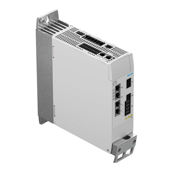
Page 15: Product Design
The cooling element has one slot each on the top and bottom for mounting the device on the rear wall of the control cabinet. If an operator unit is not required, the upper area is covered with a blind plate. Festo — CMMT-AS-C2/3/5/7/12-11A-P3-... — 2021-12e... - Page 16 The air picks up heat from the profile in the process. Top slot (keyhole shape) Retaining screw for braking resistor (2x) Braking resistor Bottom slot Fan (CMMT-AS-C5/C7/C12-11A-P3 only) Fig. 3: Back Festo — CMMT-AS-C2/3/5/7/12-11A-P3-... — 2021-12e...
-
Page 17: Overview Of Connection Technology
[XF1 IN] RTE interface port 1 [X18] standard Ethernet [X1C] inputs/outputs for the axis [X5] connection for operator unit (behind the blind plate) [X6B] motor auxiliary connection [X1A] I/O interface [X6A] motor phase connection [X9B] connection for braking resistor Festo — CMMT-AS-C2/3/5/7/12-11A-P3-... — 2021-12e... - Page 18 [XF1 IN] RTE interface port 1 [X18] standard Ethernet [X1C] inputs/outputs for the axis [X5] connection for operator unit (behind the blind plate) [X6B] motor auxiliary connection [X1A] I/O interface [X6A] motor phase connection [X9B] connection for braking resistor Festo — CMMT-AS-C2/3/5/7/12-11A-P3-... — 2021-12e...
-
Page 19: Set Bus Protocol
Auto (detection or parameterisation) PROFINET EtherCAT EtherNet/IP Tab. 8: Switch setting bus protocol The switches can be adjusted with a small slotted head screwdriver. The switch position is evaluated once when the device is started. Festo — CMMT-AS-C2/3/5/7/12-11A-P3-... — 2021-12e... -
Page 20: Transport And Storage
– Store and transport the product in its original packaging. The original packaging offers sufficient protection from typical stresses. Assembly Dimensions CMMT-AS-C2/C3/C5-11A-P3... Fig. 7: Dimensions Dimen- sion [mm] Approx. Tab. 9: Dimensions CMMT-AS-C2/C3/C5-11A-P3... Part 1 Festo — CMMT-AS-C2/3/5/7/12-11A-P3-... — 2021-12e...
Need help?
Do you have a question about the CMMT-AS-C2-11A-P3 Series and is the answer not in the manual?
Questions and answers