Advertisement
Quick Links
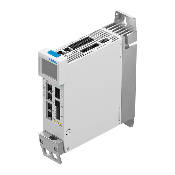
CMMT-AS-C2/3/5-11A-P3-...-S1
Servo drive
Operating instructions | Installation, Safety sub-function
8165115
2021-12c
[8165117]
Translation of the original instructions
© 2021 all rights reserved to Festo SE & Co. KG
BiSS®, EnDat®, EtherCAT®, EtherNet/IP®, HEIDENHAIN®, Hiperface®,
MODBUS®, PI PROFIBUS PROFINET®, TORX® are registered trademarks of the
respective trademark owners in certain countries.
1
About this document
1.1
Target group
The document is targeted towards persons who mount and operate the product.
It is additionally targeted towards individuals who are entrusted with the plan-
ning and application of the product in a safety-related system (safety manual in
accordance with EN 61508).
1.2
Applicable documents
All available documents for the product è www.festo.com/sp.
The user documentation for the product also includes the following documents:
Identifier
Table of contents
Operating instructions for the
Installation, safety sub-function
product
Manuals for the product
Detailed description of assembly, installation
Detailed description of safety sub-function
Manual/online help plug-in
Plug-in:
– Functions and operation of the software
– Initial commissioning wizard
Firmware functions:
– Configuration and parameterisation
– Operating modes and operational functions
– Diagnostics and optimisation
Bus protocol/control:
– Device profile
– Controller and parameterisation
– Function of the Festo Automation Suite
Festo Automation Suite online
– Management and integration of device-specific plug-ins
help
Operating instructions CDSB
General functions of the operator unit
Tab. 1: User documentation for the product
1.3
Product version
This documentation refers to the following version of the device:
– Servo drive CMMT-AS-...-S1, revision R01 and higher, see product labelling
1.4
Product labelling
•
Observe the specifications on the product.
The product labelling is located on the right side of the device. The product label-
ling enables identification of the product and shows the following information,
for example:
Product labelling (example)
CMMT-AS-C2-11A-P3-MP-S1
5340821 MM-YYYY : J302 Rev 00
Main input: 3 x 200 V AC - 10% ... 480 V AC + 10%
48 ... 62 Hz 2 A
RMS
Motor out: 3 x 0 ... Input V AC 0 ... 599 Hz
1.7 A
0.8 kW
RMS
T
: max. 40 °C
AMB
IP10/20 PD2
Festo SE & Co. KG
Ruiter Straße 82
73734 Esslingen
Deutschland
+49 711 347-0
www.festo.com
Meaning
Order code
Part number, serial number (MM = produc-
tion month, YYYY = production year, plant
number), revision (Rev)
Technical data on power supply (alternating
current supply connection)
Technical data for the motor output (output
voltage, max. output frequency, nominal cur-
rent, nominal output power)
Ambient temperature (T
)
AMB
Degree of protection, without mating plug/
with mating plug X9A attached; pollution
degree
Product labelling (example)
SCCR: 10 kA
cUL restriction: only for use in WYE 480 V/277 V
supply sources
1)
R-R-FTO-KC-2018-1054
MAC: XX-XX-XX-XX-XX-XX
See manual for additional information
Data matrix code 123456789AB
Festo SE & Co. KG
DE-73734 Esslingen
Made in Germany
1) only for product versions with corresponding restrictions
Tab. 2: Product labelling (example)
Warning symbols on the front of the product
Warnin
Meaning with the CMMT-AS-...
g
symbol
Attention! Hot surface
Metallic housing parts of the device can reach high temperatures during operation.
In the event of a fault, internal components may become overloaded. Overloading of
components can result in high temperatures and the release of hot gases.
Attention! General danger point
The touch current in the protective earthing conductor can exceed an alternating cur-
rent of 3.5 mA or a direct current of 10 mA.
Always connect both protective earthing connections to the mains-side PE connection,
the PE pin of [X9A] and PE earthing screw on the housing.
The minimum cross section of the protective earthing conductor must comply with
the local safety regulations for protective earthing conductors for equipment with high
leakage current.
Attention! Dangerous voltage
The product is equipped with DC link capacitors, which store dangerous voltage for up
to 5 minutes after the power supply is switched off. Do not touch power connections for
5 min
5 minutes after the power supply is switched off.
After the power supply is switched off, wait at least 5 minutes until the DC link capaci-
tors have discharged.
Tab. 3: Meaning of the warning symbols
Warnings on the product
The following warnings are attached to the right side of the device:
Warnings on the product (en, fr)
CAUTION
Risk of Electric Shock! Do not touch electrical connectors for
5 minutes after switching power off! Read manual before instal-
ling! High leakage current! First connect to earth!
AVERTISSEMENT
Risque du choc électrique! Une tension dangereuse peut ètre pré-
sentée jusqu'à 5 minutes aprés avoir coupé l'alimentation ! Lire le
manuel avant installation ! Courant de défaut élevée ! Relier tout
d´abord à la terre !
DANGER
Risk of Electric Shock! Disconnect power and wait 5 minutes
before servicing.
Risque du choc électrique! Débranchez l'alimentation et attendez
5 min. avant de procéder à l'entretien.
WARNING
Hot surface - Risk of burn!
ATTENTION
Risque de temperature élevée en surface!
Tab. 4: Warnings on the product
1.5
Specified standards
Version
EN 61800-5-1:2007+A1:2017
EN ISO 13849-1:2015
EN 60204-1:2018
EN 60529:1991+A1:2000+A2/AC:2019
EN 61508 Parts 1-7:2010
Tab. 5: Standards specified in the document
2
Safety
2.1
Safety instructions
General safety instructions
– Assembly and installation should only be carried out by qualified personnel.
– Only use the product if it is in perfect technical condition.
– Only use the product in its original condition without unauthorised modifica-
tions.
– Do not carry out repairs on the product. If defective, replace the product imme-
diately.
Meaning
SCCR (short circuit current rating)
Operation on power supply systems with SCCR
£ 10 kA è 13.4 Technical data UL/CSA certifi-
cation
KC mark certificate (test mark for Korea)
first MAC address of the device for Ethernet
communication
Reference to the existing user documentation,
which contains information on overload pro-
tection and the necessary external circuit
breaker.
Product key as a data matrix code and an 11-
character alphanumeric code
Manufacturer
Manufacturer's address
Country of origin Germany
Meaning
Caution
Risk of electric shock! Do not
touch electrical connections
for 5 minutes after switching
power off! Read manual before
installing! High leakage current
after PE! First connect device to
protective earthing!
Danger
Risk of electric shock! Discon-
nect power and wait 5 minutes
before servicing.
Warning
Hot surface – danger of burns!
EN 61800-2:2015
EN IEC 61800-3:2018
EN 61800-5-2:2017
EN 62061:2005+AC:2010+A1:2013+A2:2015
–
Advertisement

Related Manuals for Festo CMMT-AS-C2-11A-P3 S1 Series


Summary of Contents for Festo CMMT-AS-C2-11A-P3 S1 Series
- Page 1 Meaning with the CMMT-AS-... Translation of the original instructions symbol © 2021 all rights reserved to Festo SE & Co. KG Attention! Hot surface Metallic housing parts of the device can reach high temperatures during operation. BiSS®, EnDat®, EtherCAT®, EtherNet/IP®, HEIDENHAIN®, Hiperface®, In the event of a fault, internal components may become overloaded.
- Page 2 The safety sub-function SBC is intended to safely hold the motor and axis in Additional information position at standstill. – Contact the regional Festo contact if you have technical problems The safety sub-function SS1 is intended for performing a rapid stop with subse- è www.festo.com.
- Page 3 Shield clamp of motor cable interface or the separate standard Ethernet interface. [X9A] Mains and DC link circuit [X2] encoder connection 1 Festo recommends use of servo motors, electromechanical drives, lines and connection [X3] encoder connection 2 accessories from the Festo accessory programme.
- Page 4 – Safe stop 1 (SS1) with use of a suitable external safety relay unit and appro- SBC feedback via SBA diagnostic contact priate wiring of the servo drive The 2-channel switching of the brake is indicated via the SBA output. SBA is –...
-
Page 5: Installation
CMMT-AS devices. • Have an authorised electrician perform the installation according to the docu- For adjacent third-party devices, Festo recommends a distance of at least 10 mm mentation. (surface temperature of third-party device max. 40°C). The double mating plug for cross-wiring of the connection [X9A] protrudes by approx. - Page 6 Mains fuse WARNING The CMMT-AS does not have an integrated fuse at the mains input or in the DC Risk of injury from electric shock in the event of incomplete insulation at the link circuit. An external fuse is required at the mains supply of the device. A device power connections [X6A], [X9A] and [X9B].
- Page 7 Always connect PE connection on the mains side (PE rail in the control cabinet) at Connection examples the following positions: Connection plan, 3-phase mains connection – PE pin of the connection [X9A] – PE connection (earthing screw) next to the upper slot of the cooling element The cross section of the PE conductors must be at least equal to the cross section of the mains conductors L at [X9A].
- Page 8 SBC connection example [X1A] Function Description The safety sub-function SBC (safe brake control) is triggered by an input device #SBC-B Control input Safe brake that makes the safety request. control, channel B – reserved, do not connect ERR-RST Error acknowledgement CTRL-EN Power stage enable AIN0...
-
Page 9: X10], Sync In/Out
Connect the connecting cable shield to the plug housings on both sides. ECN 1113/EQN 1125 ECN 1123/EQN 1135 Possible connections EnDat 2.1 Only in conjunction with Festo motors Connection possibilities Description from the series EMMS-AS that have an integrated encoder with EnDat 2.1 pro-... - Page 10 – Only use motor cables that have been approved for operation with the Festo Thermal memory in servo drive. Motor cables of other manufacturers are permitted if they meet the the event of a power supply failure specified requirements.
- Page 11 Motor cable shield support on the motor side Detailed information on the motor-side connection with motor cables from Festo Tab. 37: Tightening torque and clamping range CMMT-AS-...-C2/C3/C5-11A-P3 è Assembly instructions for the motor cable è www.festo.com/sp.
- Page 12 Requirements for the connecting cables of external braking resistors Requirements for the Single device Device compound connecting cable Wiring inside the control cabinet, shield connected to Number of insulated wires and 4 insulated wires, unshielded without DC link coupling: Tightening torque of the screw terminals on the 0.5 …...
- Page 13 – Performance of a black-box test RN/MS/SF (example CMMT-AS-...-MP) Preparation for commissioning ER/NS/NF (example CMMT-AS-...-MP) For initial commissioning, you will need to have the Festo Automation Suite software installed along with the CMMT-AS plug-in è www.festo.com/sp. Ethernet interface activated [X18] Prepare for commissioning as follows: Communication activity [X18] 1.
- Page 14 1) Safety sub-function STO tested and STA diagnostic output monitored by the safety controller at least 1 x error and application, back to Festo. every 24 h. 3. Check with your regional Festo contact person to clarify the conditions for the Tab. 53: Safety reference data for the safety sub-function STO return shipment.
- Page 15 <50% rated load in S1 opera- CE marking (declaration of conformity in accordance with EU EMC Directive tion and 40 °C ambient tem- è www.festo.com/sp) in accordance with EU Machinery Directive perature in accordance with EU RoHS Directive 1) Continuous operation under constant load 1) The device is intended for use in an industrial environment and with appropriate measures in commercial, Tab.
- Page 16 – According to the UL standard, the TT system with separate neutral conductor Electrical data, logic voltage supply and PE conductor is not permitted in the overall system. CMMT-AS- C2-11A-P3 C3-11A-P3 C5-11A-P3 – UL: The integrated semiconductor short-circuit protection does not protect the Current consumption downstream power circuit.
Need help?
Do you have a question about the CMMT-AS-C2-11A-P3 S1 Series and is the answer not in the manual?
Questions and answers