Advertisement
Quick Links
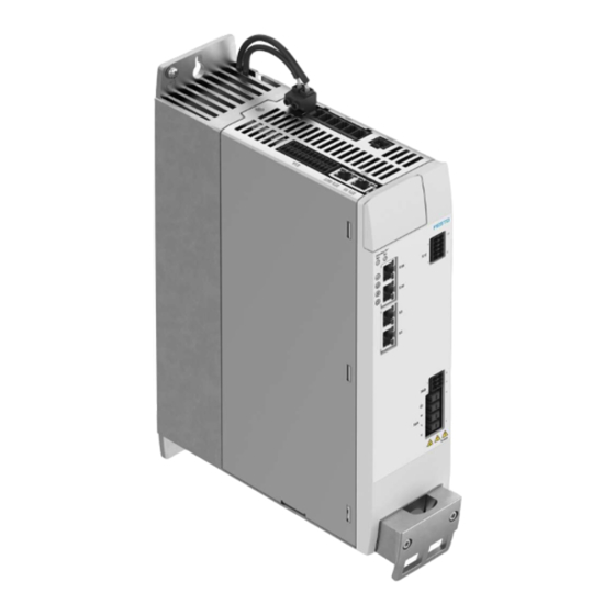
CMMT-AS-C7/12-11A-P3-S1
Servo drive
Operating instructions | Installation, Safety sub-function
8153813
2021-04b
[8153815]
Translation of the original instructions
© 2021 all rights reserved to Festo SE & Co. KG
EnDat®, EtherCAT®, EtherNet/IP®, DR. JOHANNES HEIDENHAIN®, Hiperface®,
PI PROFIBUS PROFINET®, TORX® are registered trademarks of the respective
trademark owners in certain countries.
1
About this document
1.1
Target group
The document is targeted towards persons who mount and operate the product.
It is additionally targeted towards individuals who are entrusted with the plan-
ning and application of the product in a safety-related system (safety manual in
accordance with EN 61508).
1.2
Applicable documents
All available documents for the product è www.festo.com/sp.
The user documentation for the product also includes the following documents:
Identifier
Table of contents
Operating instructions for the
Installation, safety sub-function
product
Manuals for the product
Detailed description of assembly, installation
Detailed description of safety sub-function
Manual/online help plug-in
Plug-in:
– Functions and operation of the software
– Initial commissioning wizard
Firmware functions:
– Configuration and parameterisation
– Operating modes and operational functions
– Diagnostics and optimisation
Bus protocol/control:
– Device profile
– Controller and parameterisation
– Function of the Festo Automation Suite
Festo Automation Suite online
– Management and integration of device-specific plug-ins
help
Operating instructions CDSB
General functions of the operator unit
Tab. 1: User documentation for the product
1.3
Product version
This documentation refers to the following version of the device:
– Servo drive CMMT-AS-...-S1, revision R01 and higher, see product labelling
1.4
Product labelling
•
Observe the specifications on the product.
The product labelling is located on the right side of the device. The product label-
ling enables identification of the product and shows the following information,
for example:
Product labelling (example)
CMMT-AS-C7-11A-P3-EC-S1
8101907 MM-YYYY : J302 Rev 00
Main input: 3 x 200 V AC - 10% ... 480 V AC + 10%
48 ... 62 Hz 7 A
RMS
Motor out: 3 x 0 ... Input V AC 0 ... 599 Hz 7 A
4 kW
T
: max. 40 °C
AMB
IP10/20 PD2
Festo SE & Co. KG
Ruiter Straße 82
73734 Esslingen
Deutschland
+49 711 347-0
www.festo.com
Meaning
Order code
Part number, serial number (MM = produc-
tion month, YYYY = production year, plant
number), revision (Rev)
Technical data on power supply (alternating
current supply connection)
Technical data for the motor output (output
RMS
voltage, max. output frequency, nominal cur-
rent, nominal output power)
Ambient temperature (T
)
AMB
Degree of protection, without mating plug/
with mating plug X9A attached; pollution
degree
Product labelling (example)
SCCR: 10 kA
R-R-FTO-KC-2018-1054
MAC: XX-XX-XX-XX-XX-XX
See manual for additional information
Data matrix code 123456789AB
Festo SE & Co. KG
DE-73734 Esslingen
Made in Germany
Tab. 2: Product labelling (example)
Warning symbols on the front of the product
Warnin
Meaning with the CMMT-AS-...
g
symbol
Attention! Hot surface
Metallic housing parts of the device can reach high temperatures during operation.
In the event of a fault, internal components may become overloaded. Overloading of
components can result in high temperatures and the release of hot gases.
Attention! General danger point
The touch current in the protective earthing conductor can exceed an alternating cur-
rent of 3.5 mA or a direct current of 10 mA.
Always connect both protective earthing connections to the mains-side PE connection,
the PE pin of [X9A] and PE earthing screw on the housing.
The minimum cross section of the protective earthing conductor must comply with
the local safety regulations for protective earthing conductors for equipment with high
leakage current.
Attention! Dangerous voltage
The product is equipped with DC link capacitors, which store dangerous voltage for up
to 5 minutes after the power supply is switched off. Do not touch power connections for
5 min
5 minutes after the power supply is switched off.
After the power supply is switched off, wait at least 5 minutes until the DC link capaci-
tors have discharged.
Tab. 3: Meaning of the warning symbols
Warnings on the product
The following warnings are attached to the right side of the device:
Warnings on the product (en, fr)
CAUTION
Risk of Electric Shock! Do not touch electrical connectors for
5 minutes after switching power off! Read manual before instal-
ling! High leakage current! First connect to earth!
AVERTISSEMENT
Risque du choc électrique! Une tension dangereuse peut ètre pré-
sentée jusqu'à 5 minutes aprés avoir coupé l'alimentation ! Lire le
manuel avant installation ! Courant de défaut élevée ! Relier tout
d´abord à la terre !
DANGER
Risk of Electric Shock! Disconnect power and wait 5 minutes
before servicing.
Risque du choc électrique! Débranchez l'alimentation et attendez
5 min. avant de procéder à l'entretien.
WARNING
Hot surface - Risk of burn!
ATTENTION
Risque de temperature élevée en surface!
Tab. 4: Warnings on the product
1.5
Specified standards
Version
IEC 61800-5-1:2016
EN ISO 13849-1:2015
EN 60204-1:2006+A1:2009+AC2010
EN 60529:1991+A1:2000+A2/AC:2019
EN 61508 Parts 1-7:2010
Tab. 5: Standards specified in the document
2
Safety
2.1
Safety instructions
General safety instructions
– Assembly and installation should only be carried out by qualified personnel.
– Only use the product if it is in perfect technical condition.
– Only use the product in original status without unauthorised modifications.
– Do not carry out repairs on the product. If defective, replace the product imme-
diately.
– Observe labelling on the product.
– Take into consideration the ambient conditions at the location of use.
The safety function might fail and malfunctions might occur if you do not
comply with the parameters required for the ambient and connection condi-
tions.
Meaning
SCCR (short circuit current rating)
KC mark certificate (test mark for Korea)
first MAC address of the device for Ethernet
communication
Reference to the existing user documentation,
which contains information on overload pro-
tection and the necessary external circuit
breaker.
Product key as a data matrix code and an 11-
character alphanumeric code
Manufacturer
Manufacturer's address
Country of origin Germany
Meaning
Caution
Risk of electric shock! Do not
touch electrical connections
for 5 minutes after switching
power off! Read manual before
installing! High leakage current
after PE! First connect device to
protective earthing!
Danger
Risk of electric shock! Discon-
nect power and wait 5 minutes
before servicing.
Warning
Hot surface – danger of burns!
EN 61800-2:2015
EN 61800-3:2004+A1:2012
EN 61800-5-2:2017
EN 62061:2005+AC:2010+A1:2013+A2:2015
–
Advertisement

Subscribe to Our Youtube Channel
Related Manuals for Festo CMMT-AS-C7-11A-P3-EC-S1


Summary of Contents for Festo CMMT-AS-C7-11A-P3-EC-S1
- Page 1 In the event of a fault, internal components may become overloaded. Overloading of components can result in high temperatures and the release of hot gases. © 2021 all rights reserved to Festo SE & Co. KG Attention! General danger point The touch current in the protective earthing conductor can exceed an alternating cur- EnDat®, EtherCAT®, EtherNet/IP®, DR.
- Page 2 The safety sub-function STO is intended to switch off the torque of the connected Additional information motor, thereby preventing an unexpected restart of the motor. – Contact the regional Festo contact if you have technical problems The safety sub-function SBC is intended to safely hold the motor and axis in è www.festo.com.
- Page 3 The device can be parameterised via a PC using either the real-time Ethernet interface or the separate standard Ethernet interface. Festo recommends use of servo motors, electromechanical drives, lines and Fig. 2: Connections of the CMMT-AS-C7/C12-11A-P3 (example) accessories from the Festo accessory programme.
- Page 4 Brake test The STA diagnostic output indicates whether the safe status has been reached for the safety sub-function STO. The STA diagnostic output switches to high level only • Check whether a brake test is required. The DGUV information sheet “Gravity- when STO is active on 2 channels via the control inputs #STO-A and #STO-B.
- Page 5 CMMT-AS devices. death. For adjacent third-party devices, Festo recommends a distance of at least 10 mm Before commissioning, also for brief measuring and test purposes: (surface temperature of third-party device max. 40°C). The double mating plug •...
- Page 6 – Comply with all specified requirements, e.g.: Line protection requirements – Surrounding area (EMC) Description Cable cross Mains fuse [A] – Logic and load voltage supply section at – Mating plug [X9A] in – Connecting cables [mm²] – Cross-wiring – Additional information è Manual Assembly, Installation. CMMT-AS- C7-11A-P3 C12-11A-P3...
- Page 7 Information on EMC-compliant installation A mains filter is integrated into the device. The mains filter fulfils the following tasks: – Guarantees the device’s immunity to interference – Limits the conducted emissions of the device The device fulfills the requirements of the relevant product standard EN 61800-3 with suitable installation and wiring of all connecting cables.
- Page 8 ECN 1113/EQN 1125 ECN 1123/EQN 1135 Shielding Unshielded EnDat 2.1 Only in conjunction with Festo motors Min. conductor cross section incl. 0.25 mm – from the series EMMS-AS that have an wire end sleeve with plastic sleeve integrated encoder with EnDat 2.1 pro- Max.
- Page 9 A maximum of 16 devices may be connected. first motor phase cables and a connector box (accessories Recommendation: use Cat 5e category patch è www.festo.com/catalogue) cables; maximum length per cable: 100 cm Tab. 24: Connection possibilities 7.8.6 [X18], Standard Ethernet The interface [X18] is located on the front of the device.
- Page 10 – Parameterise I²t monitoring with speed- Speed-sensitive over- supported from firmware – Only use motor cables that have been approved for operation with the Festo load protection version V019, parameteris- dependent scaling, e.g. with the device- servo drive. Motor cables of other manufacturers are permitted if they meet the able specific plug-in.
- Page 11 Reference potential for logic voltage supply Motor cable shield support on the motor side Detailed information on the motor-side connection with motor cables from Festo è Assembly instructions for the motor cable è www.festo.com/sp. • Connect all shields to the PE over a wide surface area on the motor side, e.g.
- Page 12 Holding brake (negative potential) Preparation for commissioning Tab. 43: Inputs and outputs for the SBC safety sub-function For initial commissioning, you will need to have the Festo Automation Suite 7.14 SS1 installation software installed along with the CMMT-AS plug-in è www.festo.com/spè .
- Page 13 Encoder status, encoder interface (servo drive, motor, axis, etc.) match those that are connected exactly. [X3] During initial commissioning with the Festo Automation Suite with the CMMT-AS Encoder status, encoder interface plug-in installed, the following steps must be performed, for example: [X2] 1.
- Page 14 STA evalua- error and application, back to Festo. evaluation tion 3. Check with your regional Festo contact person to clarify the conditions for the Common cause factor for return shipment. dangerous undetected fail- ures β in accordance with Disassembly EN 61508 Disassemble in reverse order of installation.
- Page 15 Ambient conditions, transport Electrical data, load voltage supply [X9A] Relative humidity 5 … 95 (non-condensing) CMMT-AS- C7-11A-P3 C12-11A-P3 Max. transportation duration Mains current consumption at nominal power approx. Permissible altitude 12000 (above sea level) for 12 h Short circuit current rating [kA] Vibration resistance Vibration test and free fall in packaging in accordance...
- Page 16 UL/CSA certification information UL mark UL control number 4PU8 Tab. 63: UL/CSA certification information – Use in an environment with pollution degree 2 (or better). – Use only Cu cables that have a permissible constant insulation temperature of at least 75 °C at the following connections: –...
Need help?
Do you have a question about the CMMT-AS-C7-11A-P3-EC-S1 and is the answer not in the manual?
Questions and answers