Festo CMMT-ST-C8-1C-...-S0 Series Original Instructions Manual
Hide thumbs
Also See for CMMT-ST-C8-1C-...-S0 Series:
- Instructions manual (13 pages) ,
- Operating instructions manual (11 pages) ,
- Manual (32 pages)

Subscribe to Our Youtube Channel
Related Manuals for Festo CMMT-ST-C8-1C-...-S0 Series


Summary of Contents for Festo CMMT-ST-C8-1C-...-S0 Series
- Page 1 CMMT-ST-C8-1C-...-S0 Servo drive Description | Assembly, Installation 8097118 8097118 2019-01 [8097120]...
- Page 2 Translation of the original instructions ® ® ® ® ® ® ® AKULON , BISS , CiA , EtherCAT , EtherNet/IP , PI PROFIBUS PROFINET , PHOENIX CONTACT registered trademarks of the respective trademark owners in certain countries. Festo — CMMT-ST-C8-1C-...-S0 — 2019-01...
-
Page 3: Table Of Contents
[XF1 IN] and [XF2 OUT], real-time Ethernet (RTE) port 1 and 2......... 32 Motor connection......................34 Load and logic power supply..................36 Cross-wiring of several servo drives................37 Malfunctions....................... 38 Diagnostics via LEDs..................... 38 9.1.1 Device status displays.................... 39 Festo — CMMT-ST-C8-1C-...-S0 — 2019-01... - Page 4 Encoder interfaces [X2]..................53 11.3.4 Digital inputs and outputs [X1A]................54 11.3.5 Reference switch [X1C]................... 57 11.3.6 Standard Ethernet [X18], parameterisation interface..........58 11.3.7 Real-time Ethernet [XF1 IN], [XF2 OUT]..............58 11.4 Characteristic curves..................... 59 Festo — CMMT-ST-C8-1C-...-S0 — 2019-01...
-
Page 5: About This Document
Target group The document is targeted towards individuals who perform assembly, installation and service work on the product. Applicable documents All available documents for the product è www.festo.com/pk. The user documentation for the product also includes the following documents: Designation Contents... -
Page 6: Product Labelling
R-R-FTO-KC-2018-1092 KC mark certificate (test mark for Korea) 01/205/5696.00/19 TÜV certificate number Data matrix code, 123456789AB Product key as a data matrix code and an 11-character alphanumeric code Festo AG & Co. KG Manufacturer DE-73734 Esslingen Manufacturer’s address Festo — CMMT-ST-C8-1C-...-S0 — 2019-01... -
Page 7: Specified Standards
Attention! Hot surface Metallic housing parts of the device can reach high temperatures during operation. Tab. 4 Meaning of the warning symbol Specified standards Version EN 60204-1:2018-09 EN 61800-3:2004+A1:2012 EN 61131-2:2007 EN 61800-5-2:2017 Tab. 5 Standards specified in the document Festo — CMMT-ST-C8-1C-...-S0 — 2019-01... -
Page 8: Safety
In its original condition, without unauthorised modifications – Within the limits of the product defined by the technical data è 11 Technical data – In an industrial environment Intended use of the safety sub-functions for the product è Description Safety sub-function. Festo — CMMT-ST-C8-1C-...-S0 — 2019-01... -
Page 9: Range Of Application
Approvals and certifications The product has the CE marking. For details of directives, see è 11.1 Technical data, product conformity and approvals. The product-related EU directives and standards are listed in the declaration of conformity è www.festo.com/sp. Festo — CMMT-ST-C8-1C-...-S0 — 2019-01... -
Page 10: Additional Information
Spare parts è www.festo.com/spareparts. – All available documents for the product and current versions of the firmware and commissioning software è www.festo.com/sp. Service Contact your regional Festo contact person if you have technical questions è www.festo.com. Product overview Scope of delivery Component Number Servo drive CMMT-ST-... -
Page 11: System Structure
The servo drive CMMT-ST is a 1-axis servo drive for controlling a stepper motor or an EC motor with connected mechanisms, e.g. an axis from Festo. The device is controlled by a higher-level controller using the bus protocol EtherCAT, EtherNet/IP or PROFINET, depending on the product version, via a real time Ethernet interface. -
Page 12: Product Design
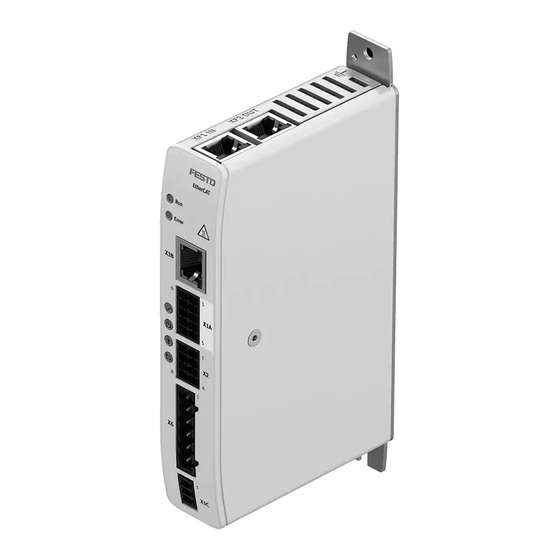
The device does not have a fan. 1 Top 4 Cooling element (metal housing parts, top, bottom left side and back of housing) 2 Front side 5 Ventilation slots 3 Bottom Fig. 4 Servo drive CMMT-ST Festo — CMMT-ST-C8-1C-...-S0 — 2019-01... - Page 13 Fig. 5 Elements on the back There is a hole at the top and a slot for wall mounting at the bottom of the back. The t-rail clamp is mounted in the centre of the back. Festo — CMMT-ST-C8-1C-...-S0 — 2019-01...
- Page 14 Product overview 1 Ventilation slots 2 Bottom of the CMMT-ST Fig. 6 Bottom Festo — CMMT-ST-C8-1C-...-S0 — 2019-01...
-
Page 15: Overview Of Connection Technology
4 [XF1 IN] RTE interface port 1 9 [X1C] Connection for the reference switch or limit switch 5 [X18] Standard Ethernet 10 [X9] Load and logic voltage (underneath) Fig. 7 Connections of the CMMT-ST (example CMMT-ST-C8-1C-EC) Festo — CMMT-ST-C8-1C-...-S0 — 2019-01... -
Page 16: Transport And Storage
Mechanical stresses – Impermissible temperatures – Moisture – Aggressive atmospheres – Store and transport the product in its original packaging or installed in the control cabinet. The original packaging offers sufficient protection from typical stresses. Festo — CMMT-ST-C8-1C-...-S0 — 2019-01... -
Page 17: Assembly
Detailed information about the required mounting clearances and any power reduction that may be necessary as a function of the ambient temperature è Fig.16 Festo — CMMT-ST-C8-1C-...-S0 — 2019-01... - Page 18 The necessary clearances are determined by the temperature in the control cabinet and the required effective current. The PositioningDrives software from Festo can help to calculate the effective current. If the clearances are set too low, the device will be switched off by the I²t or temperature monitoring function of the output stage.
-
Page 19: Installation
The servo drive can be screwed onto the backwall of the control cabinet or mounted on an H-rail. Assembly instructions – Always install the device vertically in the control cabinet (mains supply line [X9] underneath). Festo — CMMT-ST-C8-1C-...-S0 — 2019-01... - Page 20 1. Attach the device by hooking the top of the H-rail clamp onto the H-rail from above. 2. Press the lower part of the device onto the H-rail until the H-rail clamp clicks into place on the H- rail. Fig. 10 Mounting on an H-rail Festo — CMMT-ST-C8-1C-...-S0 — 2019-01...
-
Page 21: Installation
[X1C] Inputs/outputs for the refer- ence/limit switches [X2] Encoder Not required but twisted in pairs [X6] Motor phase connection Not required but twisted in pairs [X9] Logic power supply and load Not required power supply Festo — CMMT-ST-C8-1C-...-S0 — 2019-01... - Page 22 RTE (port 2) 1) Adhere to the maximum permissible cable length for the encoder used. 2) Shielded cables from Festo can be used. The shield can only be connected on the motor side. Tab. 10 Cable lengths and cable shield Laying cables Comply with general guidelines for EMC-compliant installation, e.g.:...
-
Page 23: Connection Example
1 BiSS-C or incremental encoder 3 PELV fixed power supply for logic voltage (24 V) 2 EC motor or stepper motor 4 PELV fixed power supply for load voltage (24 V … 48 V) Fig. 11 Connection example Festo — CMMT-ST-C8-1C-...-S0 — 2019-01... -
Page 24: Interfaces
Via high-side driver (delivers cur- rent) Tab. 11 PNP logic Signal Level Input Output Logic 0 24 V Internal via pull-up resistor Internal via pull-up resistor – Logic 1 0 V Via low-side driver (consumes cur- rent) Tab. 12 NPN logic Festo — CMMT-ST-C8-1C-...-S0 — 2019-01... - Page 25 Installation Connection examples Fig. 12 Connection example, PNP logic Festo — CMMT-ST-C8-1C-...-S0 — 2019-01...
- Page 26 Installation Fig. 13 Connection example, NPN logic Festo — CMMT-ST-C8-1C-...-S0 — 2019-01...
- Page 27 Included in assortment of plugs NEKM-C-22 (enclosed with the product) Signal contacts 10 (10-pin, 2-row) Nominal current 8 A Grid dimension 3.5 mm Strip length 10 mm UL Use Group Tab. 14 Mating plug requirements Connecting cable requirements Shielding Not required Festo — CMMT-ST-C8-1C-...-S0 — 2019-01...
-
Page 28: X1C], Reference Switch/Limit Switch
Strip length 9 mm UL Use Group Tab. 17 Mating plug requirements Cable requirements Shielding Not required Min. conductor cross section incl. plastic cable end sleeve 0.14 mm Max. conductor cross section incl. plastic cable end sleeve 1.5 mm Festo — CMMT-ST-C8-1C-...-S0 — 2019-01... -
Page 29: X2], Encoder Interface
Index signal input +5 V 5 V encoder supply #A_IN A signal input, inverse #B_IN B signal input, inverse #IDX_IN Index signal input, inverse 7 Reference potential of encoder supply Tab. 19 Incremental encoders with AB signals (quadrature encoder) Festo — CMMT-ST-C8-1C-...-S0 — 2019-01... - Page 30 8 A Grid dimension 3.5 mm Strip length 10 mm UL Use Group Tab. 21 Mating plug requirements Connecting cable requirements Shielding Not required but twisted in pairs Min. conductor cross section 0.2 mm Max. conductor cross section 1.5 mm Festo — CMMT-ST-C8-1C-...-S0 — 2019-01...
-
Page 31: X18], Standard Ethernet
25 m 1) Shielded cables from Festo can be used. The shield can only be connected on the motor side. 2) The conductor cross section used must be suitable for the currents that arise. If flexible flying leads are used with plastic cable end sleeves, minimum cross sections of 0.14 mm²... -
Page 32: Xf1 In] And [Xf2 Out], Real-Time Ethernet (Rte) Port 1 And 2
[XF1 IN] and [XF2 OUT], real-time Ethernet (RTE) port 1 and 2 The real-time Ethernet interface [XF1 IN] and [XF2 OUT] is located on the top of the device. The inter- face permits RTE communication. The following protocols are supported, depending on the product version: Festo — CMMT-ST-C8-1C-...-S0 — 2019-01... - Page 33 Tab. 29 [XF1 IN] and [XF2 OUT], RTE port 1 and 2 Mating plug requirements Design VS-08-RJ45-5-Q/IP20 from Phoenix Contact or compatible Number of pins Shielded Degree of protection IP20 Tab. 30 Mating plug requirements Festo — CMMT-ST-C8-1C-...-S0 — 2019-01...
-
Page 34: Motor Connection
Pin allocation for connecting a stepper motor: [X6] Function Description Mating plug labelling String A String A/ String B String B/ Brake +24 V Br-/0 V Brake 0 V Br-/ Tab. 32 Motor phase connection for connecting a stepper motor Festo — CMMT-ST-C8-1C-...-S0 — 2019-01... - Page 35 1) Only 10 A are permissible for the cUL approval. Tab. 34 Mating plug requirements Connecting cable requirements Shielding Not required but twisted in pairs Min. conductor cross section incl. plastic 0.2 mm cable end sleeve Max. conductor cross section without cable end 2.5 mm sleeve Festo — CMMT-ST-C8-1C-...-S0 — 2019-01...
-
Page 36: Load And Logic Power Supply
Max. length 25 m 1) Shielded cables from Festo can be used. The shield can only be connected on the motor side. 2) The conductor cross section used must be suitable for the currents that arise. Tab. 35 Connecting cable requirements Festo offers prefabricated motor cables as accessories è www.festo.com/catalogue. -
Page 37: Cross-Wiring Of Several Servo Drives
Wire the diagnostic contacts of a maximum of 10 servo drives in series. The maximum cable length applies to the entire line, from the safety relay unit to the final device. Example of cross-wiring è www.festo.com/sp, Expert knowledge tab (Application note). It is not recommended to perform mixed cross-wiring of diagnostic contacts and diagnostic outputs. -
Page 38: Malfunctions
The device has LEDs for displaying status information on the top and in the RJ45 bushings [XF1 IN], [XF2 OUT] and [X18]. The following image shows an example of the LEDs on the front of product variant CMMT-ST-...-EC. The functions of the RTE network status LEDs 2 differ by product version. Festo — CMMT-ST-C8-1C-...-S0 — 2019-01... -
Page 39: Device Status Displays
After the device is switched on, it runs through an initialisation phase. When the initialisation phase is complete, the device performs an LED test. During the LED test, the 4 device status LEDs are activated simultaneously. The 4 device status LEDs light up yellow for approx. 300 ms. Festo — CMMT-ST-C8-1C-...-S0 — 2019-01... - Page 40 – Safety sub-function STO requested via 1 channel (discrepancy monitoring) – Plausibility check of STO channel switch-off Malfunctions are externally reported by the functional part, including via the additional communica- tion interfaces (bus, commissioning software). Festo — CMMT-ST-C8-1C-...-S0 — 2019-01...
- Page 41 Identification sequence active (for optical identification of the device in a network), which can be activated via the parameterisation software altern- ately betw- red, yellow green Flash- Reserved for future extensions es yel- Lights yellow Flash- green Lights green Tab. 44 Application status LED Festo — CMMT-ST-C8-1C-...-S0 — 2019-01...
-
Page 42: Interface Status [X18]
Meaning (upper LED) Interface is deactivated. Lights Interface is activated. green Tab. 46 Upper LED at [X18] Meaning (lower LED) No communication activity Flash- Communication activity detected. es yel- Tab. 47 Lower LED at [X18] Festo — CMMT-ST-C8-1C-...-S0 — 2019-01... -
Page 43: Device And Interface Status, Ethercat
Local error, the slave device application has independently changed the Ether- CAT status. This can have the following causes: – A host watchdog time-out has occurred. – Synchronisation error, the device switches automatically to the safe- operational status. Festo — CMMT-ST-C8-1C-...-S0 — 2019-01... -
Page 44: Device And Interface Status, Profinet
No error Flash- Network error Check network configuration and net- es red – No data transmission work connection. (2 Hz) – No configuration – No network connection or network connection is malfunctioning Tab. 51 NF LED Festo — CMMT-ST-C8-1C-...-S0 — 2019-01... -
Page 45: Device And Interface Status, Ethernet/Ip
Together with the 4 LEDs on the top (Link/Activity), the MS LED and NS LED on the front display the bus/network status. EtherNet/IP, MS LED; module status Meaning Remedy Logic voltage supply lacking. Check logic voltage supply. Flash- Device is not configured. Perform configuration. green – Lights Normal operating status green Festo — CMMT-ST-C8-1C-...-S0 — 2019-01... - Page 46 Check and correct IP addresses in the up red been assigned. network. Tab. 55 NS LED EtherNet/IP, LED at XF1 IN and XF2 OUT; connection status, data traffic Meaning of the green LED Remedy No network connection Check network connection. Festo — CMMT-ST-C8-1C-...-S0 — 2019-01...
-
Page 47: Disassembly
4. Disconnect all electrical cables. Disassembly for wall mounting • Loosen retaining screws (2x) and remove the device from the mounting surface. Disassembly for H-rail mounting • Carefully tilt the servo drive upwards and remove it from the H-rail. Festo — CMMT-ST-C8-1C-...-S0 — 2019-01... -
Page 48: Technical Data
– 1) The component is intended for industrial use. Outside of industrial environments, e.g. in commercial and residential/mixed-use areas, it may be necessary to take measures to suppress radio interference. Tab. 58 Product conformity and approvals Festo — CMMT-ST-C8-1C-...-S0 — 2019-01... -
Page 49: Technical Data, General
[X18], Ethernet; parameterisation and configuration via com- missioning software ( www.festo.com/sp) è – [XF1 IN], [XF2 OUT], RT Ethernet; parameterisation and con- figuration via bus protocol RT Ethernet protocol CMMT-ST-...-EC: EtherCAT CMMT-ST-...-EP: EtherNet/IP CMMT-ST-...-PN: PROFINET Tab. 60 General technical data Festo — CMMT-ST-C8-1C-...-S0 — 2019-01... - Page 50 EN 61800-5-1, Chap. 3.5 Protection class III (protective extra-low voltage) Overvoltage category Degree of contamination Vibration resistance in accord- EN 61800-5-1 and EN 61800-2 ance with Shock resistance in accordance EN 61800-2 with Festo — CMMT-ST-C8-1C-...-S0 — 2019-01...
-
Page 51: Technical Data, Electrical
Overcurrent protection input (15 A fuse, cannot be reset) – Adjustable protection against feedback on intermediate cir- cuit rise Tab. 66 Load power supply Electrical data, logic power supply [X9], pin 3 Logic voltage range [V DC] 24 ± 15 % Festo — CMMT-ST-C8-1C-...-S0 — 2019-01... -
Page 52: Power Specifications, Motor Connection [X6]
Output of holding brake at [X6] Design High-side switch Max. continuous out- 1 (parameterisable holding current reduction) put current Max. voltage drop from [V DC] + 24 V input at connec- tion [X9] to brake out- put at [X6] Festo — CMMT-ST-C8-1C-...-S0 — 2019-01... -
Page 53: Encoder Interfaces [X2]
No overload protection Tab. 71 Digital incremental encoder at [X2] Absolut encoder with BiSS C protocol Supply 5.25 Resolution can be parameterised - default: 16 bit Support: mechanical multiturn encoder Support: battery-buf- fered multiturn encoder Festo — CMMT-ST-C8-1C-...-S0 — 2019-01... -
Page 54: Digital Inputs And Outputs [X1A]
(I L max Min. input current in [mA] transition range (I T min Tolerance for low test pulses Tolerated low test [ms] pulses (t ) up to STO,TP max. Min. time between low [ms] test pulses Festo — CMMT-ST-C8-1C-...-S0 — 2019-01... - Page 55 Digital inputs without safety inputs at [X1A] Specification Based on type 3 to EN 61131-2; deviating current consumption Nominal voltage [V DC] Permissible voltage [V DC] −3 30 … range Min. input current in [mA] transition range (I T min Festo — CMMT-ST-C8-1C-...-S0 — 2019-01...
- Page 56 Digital outputs at [X1A] (X1A.9 and X1A.10) Design PNP operation: high-side switch NPN operation: low-side switch Characteristics – Freely configurable – Not galvanically isolated Voltage range [V DC] 0 30 … Permissible output cur- [mA] rent Festo — CMMT-ST-C8-1C-...-S0 — 2019-01...
-
Page 57: Reference Switch [X1C]
< < ware during switch-off Max. input voltage, high level (U ) high H max level Min. input voltage, Typical 11 Typical 0 high level (U Max. 13 H min Max. input voltage ) low level L max Festo — CMMT-ST-C8-1C-...-S0 — 2019-01... -
Page 58: Standard Ethernet [X18], Parameterisation Interface
Tab. 80 Standard Ethernet [X18] 11.3.7 Real-time Ethernet [XF1 IN], [XF2 OUT] Real-time Ethernet [XF1 IN], [XF2 OUT] Design RTE communication, physical level toIEEE 802.3:2012-00 Bus connection design RJ45 [XF1 IN] Bus connection design RJ45 [XF2 OUT] Festo — CMMT-ST-C8-1C-...-S0 — 2019-01... -
Page 59: Characteristic Curves
Mounting clearances from 0 mm are possible for a device compound consisting of several servo drives CMMT-ST. The following characteristic curves show the maximum permissible effective currents for the lateral mounting clearances 0 mm, 3 mm, 10 mm and 15 mm. Festo — CMMT-ST-C8-1C-...-S0 — 2019-01... - Page 60 Technical data 1 Mounting clearance 15 mm 3 Mounting clearance 3 mm 2 Mounting clearance 10 mm 4 Mounting clearance 0 mm Fig. 16 Power reduction as a function of the ambient temperature and mounting clearance Festo — CMMT-ST-C8-1C-...-S0 — 2019-01...
- Page 62 Copyright: Festo AG & Co. KG Ruiter Straße 82 73734 Esslingen Germany Phone: +49 711 347-0 Fax: +49 711 347-2144 Reproduction, distribution or sale of this document or communic- e-mail: ation of its contents to others without express authorization is service_international@festo.com...
Need help?
Do you have a question about the CMMT-ST-C8-1C-...-S0 Series and is the answer not in the manual?
Questions and answers