
Subscribe to Our Youtube Channel
Related Manuals for Festo CMMT-AS Series


Summary of Contents for Festo CMMT-AS Series
- Page 1 CMMT-AS-...-S1 Servo drive Manual | Safety sub-function | STO, SBC, SS1 8153822 2021-04d [8153824]...
- Page 2 Translation of the original instructions ET 200SP , PNOZ , Pilz , SIEMENS are registered trademarks of the respective trademark owners in ® ® ® ® certain countries.
-
Page 3: Table Of Contents
General technical data........... . . 36 Festo — CMMT-AS-...-S1 — 2021-04d... - Page 4 Inputs and outputs for the axis [X1C] ....... . . 42 Festo — CMMT-AS-...-S1 — 2021-04d...
-
Page 5: About This Document
• Observe the safety instructions in the documentation è Operating instructions Assembly Installa- tion Safety sub-function. All available documents for the product è www.festo.com/sp. Product version This documentation refers to the following version of the device: – Servo drive CMMT-AS-...-S1, revision R01 and higher, see product labelling Product labelling Product labelling è... -
Page 6: Intended Use
– Annex D.3.5 and D.3.6 for motors – Annex D.3.1 for motor and brake cables – Annex D.3.4 for mating plugs Components approved by Festo for the CMMT-AS fulfil these requirements. Foreseeable misuse Foreseeable misuse, general – Use outside the limits of the product defined in the technical data. -
Page 7: Training Of Qualified Personnel
The product is a safety device in accordance with the Machinery Directive. For details of the safety-ori- ented standards and test values that the product complies with and fulfils, see è 9.1 Technical data, safety engineering. Additional information – Contact the regional Festo contact if you have technical problems è www.festo.com. Festo — CMMT-AS-...-S1 — 2021-04d... -
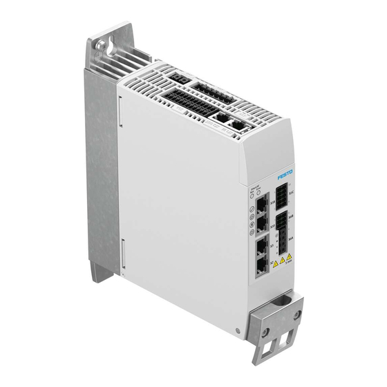
Page 8: Product Overview
Examples: • Rotating motor, synchronous machine, 8-pin è Movement < 45° at the motor shaft • Linear motor, pole pitch 20 mm è Movement < 20 mm at the moving part Festo — CMMT-AS-...-S1 — 2021-04d... - Page 9 1 High-side power stage 3 DC link voltage 2 Low-side power stage STO request The safety sub-function STO is requested on 2 channels by simultaneously switching off the control voltage at both control inputs #STO-A and #STO-B. Festo — CMMT-AS-...-S1 — 2021-04d...
- Page 10 STO request. The level of STA must change according to the logic table. The safety relay unit can cyclically test the signals #STO-A and #STO-B for high level with low test pulses and for low level with high test pulses. Festo — CMMT-AS-...-S1 — 2021-04d...
- Page 11 Internal triggering, pulse-width modulation driver high side/low side Length, low test pulses at #STO-A/B STO,TP Max. delay until STO switches off (≤ permissible reaction time when a safety STO,In sub-function is requested Feedback, STO active Festo — CMMT-AS-...-S1 — 2021-04d...
-
Page 12: Safety Sub-Function Sbc
Check whether safety sub-function SS1 is better suited to your application. SBC may only be used for holding brakes or clamping units which engage in the de-energised state. Ensure the lines are protected when installed. Festo — CMMT-AS-...-S1 — 2021-04d... - Page 13 (switched off ). Test pulses that occur simultaneously at SBC-A and SBC-B are not filtered. For this reason, the SBA diagnostic output delivers a high level signal for the duration of these low test pulses. Festo — CMMT-AS-...-S1 — 2021-04d...
- Page 14 Recommendation: evaluation with every actuation. • Check SBA feedback whenever there is a request. #SBC-A (BR+) #SBC-B (BR-Ext) Low level Low level High level High level High level Low level Tab. 5: Evaluation of SBC level Festo — CMMT-AS-...-S1 — 2021-04d...
- Page 15 2-channel input for SBC request Length of low test pulses at #SBC-A/B SBC,TP Max. delay until the related brake output is switched off (≤ permissible SBC,In reaction time when a safety sub-function is requested Feedback, SBC active Festo — CMMT-AS-...-S1 — 2021-04d...
-
Page 16: Safety Sub-Function Ss1
Check whether a brake test is required. The DGUV information sheet “Gravity-loaded axis” pro- vides information on this. 4.1.4 Safety sub-function SS1 Fig. 8: Symbol for SS1 The function described here implements the safety sub-function SS1-t according to EN 61800-5-2. Festo — CMMT-AS-...-S1 — 2021-04d... - Page 17 3. Safety sub-function STO requested plus – if required – SBC once the delay time has elapsed. The figure below shows the necessary logic circuits for the safety relay unit: Logic in the safety relay unit for SS1 Festo — CMMT-AS-...-S1 — 2021-04d...
- Page 18 Fig. 9: Logic in the safety relay unit for SS1 The delay times are directly included in the reaction time of the system. SS1 feedback The STA signal can be used as feedback for the safety sub-function SS1. Festo — CMMT-AS-...-S1 — 2021-04d...
- Page 19 2-channel input for SBC request Feedback, STO active Feedback, SBC active Braking ramp followed, rotational speed = 0 (functionally) Brake closed and power stage switched off (functionally) Rotational speed Tab. 7: Legend for SS1 timing Festo — CMMT-AS-...-S1 — 2021-04d...
-
Page 20: Cross Wiring Of Several Servo Drives
è STO feedback via STA diagnostic contact and è SBC feedback via SBA diagnostic contact. 4.1.6 Fault exclusion Put suitable measures in place to prevent faulty wiring: Festo — CMMT-AS-...-S1 — 2021-04d... -
Page 21: Safety Relay Unit
The interfaces of the PDS(SR) (Power Drive System, safety related) to the outside world are: – Power supply – Inputs and diagnostic check-back signals – Movement of the shaft – Output for controlling a second brake Interfaces of the PDS Fig. 12: Interfaces of the PDS Festo — CMMT-AS-...-S1 — 2021-04d... -
Page 22: Installation
– The safety relay unit and its inputs and outputs must meet the necessary safety classification of the safety function that is required for the specific case. – Connect each of the control inputs to the safety relay unit on 2 channels using parallel wiring. Festo — CMMT-AS-...-S1 — 2021-04d... -
Page 23: Sto Installation
Tab. 8: Inputs and outputs for the safety sub-function STO STO connection example The safety sub-function STO (safe torque off ) is triggered by an input device that makes the safety request (e.g. light curtain). Festo — CMMT-AS-...-S1 — 2021-04d... - Page 24 [X1A]. This safety request results in the 2-channel switch-off of the driver supply to the servo drive’s power output stage. The safety relay unit can use the STA diagnostic output to monitor whether the safe status has been reached for the safety sub-function STO. Festo — CMMT-AS-...-S1 — 2021-04d...
-
Page 25: Sbc Installation
Holding brake (negative potential) Tab. 9: Inputs and outputs for the SBC safety sub-function SBC connection example The safety sub-function SBC (safe brake control) is triggered by an input device that makes the safety request. Festo — CMMT-AS-...-S1 — 2021-04d... - Page 26 This shuts off power to the control of the external clamping unit. The clamping unit closes. – The safety relay unit monitors the SBA diagnostic output and checks whether the safe status has been reached for the safety sub-function SBC. Festo — CMMT-AS-...-S1 — 2021-04d...
-
Page 27: Ss1 Installation
1 Input device for safety request 3 Servo drive CMMT-AS 2 Safety relay unit Installation for operation without safety sub-function Minimum wiring for operation without safety sub-function For operation without the safety sub-function, wire inputs X1A.9 to X1A.12 as follows: Festo — CMMT-AS-...-S1 — 2021-04d... -
Page 28: Commissioning
The following check lists are no substitute for safety training. No guarantee can be provided for the completeness of the check lists. Festo — CMMT-AS-...-S1 — 2021-04d... - Page 29 Inspection of components: Is the CMMT-AS-...-S1 being used (check Yes o using the rating plate)? No o b) Is the wiring correct (check using the circuit diagram)? Yes o No o Festo — CMMT-AS-...-S1 — 2021-04d...
- Page 30 CMMT-AS when the safety sub-function is requested via 1 channel? Tab. 12: Questions for validation in accordance with EN ISO 13849-2 (example) Festo — CMMT-AS-...-S1 — 2021-04d...
-
Page 31: Operation
Error in the safety part or a safety condition has been violated. s red Flashe The safety sub-function has been requested but is not yet active. yellow Illumi- The safety sub-function has been requested and is active. nated yellow Festo — CMMT-AS-...-S1 — 2021-04d... -
Page 32: Repair
2. Send the defective product unchanged, together with a description of the error and application, back to Festo. 3. Check with your regional Festo contact person to clarify the conditions for the return shipment. Technical data Technical data, safety engineering... - Page 33 EN 61508, PFH Mean time to 2400 1960 1960 dangerous failure in accordance with EN ISO 13849-1, MTTF Average diagnostic coverage in accordance with EN ISO 13849-1, Operating life (mission time) in accordance with EN ISO 13849-1, Festo — CMMT-AS-...-S1 — 2021-04d...
- Page 34 SIL CL 3 SIL CL 1 subsystem in accord- ance with EN 62061 Category in accordance Cat. 3 Cat. 1 with EN ISO 13849-1 Performance level PL e PL c in accordance with EN ISO 13849-1 Festo — CMMT-AS-...-S1 — 2021-04d...
- Page 35 3) Brake connected either to BR+/BR− or to BR-EXT; 1-channel request via the safety controller using #SBC-A and #SBC-B; both inputs must be bridged externally. Tab. 17: Safety reference data for the safety sub-function SBC Remarks Festo — CMMT-AS-...-S1 — 2021-04d...
-
Page 36: General Technical Data
Product weight è Manual Assembly, Installation. Tab. 19: General technical data Ambient conditions, transport Transport temperature [°C] −25 … +70 Relative humidity 5 … 95 (non-condensing) Max. transportation duration Festo — CMMT-AS-...-S1 — 2021-04d... - Page 37 IP10) EN 60529 Requirements for Use in a control cabinet with at least IP54, design as “closed installation space electrical operating area” in accordance with IEC 61800-5-1, Chap. 3.5 Festo — CMMT-AS-...-S1 — 2021-04d...
-
Page 38: Technical Data, Electrical
1) The test pulses of the associated control input #SBC-A are mapped to the output subject to a switching delay. 2) Brake output also shuts down in the event of a fault if there is an overvoltage on the logic supply. Tab. 24: Output of holding brake [X6B] Festo — CMMT-AS-...-S1 — 2021-04d... -
Page 39: Inputs, Outputs, Ready Contact At [X1A]
H max Min. input voltage high-level (U H min Max. input voltage low- level (U L max Min. input voltage low- –3 level (U L min Max. input current with [mA] high-level (I H max Festo — CMMT-AS-...-S1 — 2021-04d... - Page 40 Control inputs #SBC-A and #SBC-B at [X1A] Specification Based on type 3 to EN 61131-2 Nominal voltage [V DC] Permissible voltage [V DC] –3 … 30 range Max. input voltage high-level (U H max Min. input voltage high-level (U H min Festo — CMMT-AS-...-S1 — 2021-04d...
- Page 41 1) High test pulses must not occur simultaneously at inputs #SBC-A and #SBC-B but only with a time offset. Tab. 26: Control inputs #SBC-A and #SBC-B at [X1A] Diagnostic outputs STA and SBA at [X1A] Design Asymmetrical push-pull output Voltage range [V DC] 18 … 30 Permissible output cur- [mA] rent for high-level Festo — CMMT-AS-...-S1 — 2021-04d...
-
Page 42: Inputs And Outputs For The Axis [X1C]
Permissible output cur- [mA] rent for high level < 3 Voltage loss at high level < 50 Pull-down resistance [kΩ] – Short-circuit proof Protective function – Feedback-proof – Overvoltage-resistant up to 60 V – Thermal overload protection Festo — CMMT-AS-...-S1 — 2021-04d... - Page 43 Resistive load (min.) [Ω] < 100 Inductive load [mH] < 10 Capacitive load [nF] 1) The test pulses of the associated control input #SBC-B are mapped to BR-EXT subject to a switching delay. Tab. 28: Output BR-EXT Festo — CMMT-AS-...-S1 — 2021-04d...
- Page 44 Copyright: Festo SE & Co. KG 73734 Esslingen Ruiter Straße 82 Deutschland Phone: +49 711 347-0 Internet: © 2021 all rights reserved to Festo SE & Co. KG www.festo.com...
Need help?
Do you have a question about the CMMT-AS Series and is the answer not in the manual?
Questions and answers