
Related Manuals for R.V.R. Elettronica PJ250-NV


Summary of Contents for R.V.R. Elettronica PJ250-NV
- Page 1 PJ250-NV T E C H N I C A L A N D M A I N T E N A N C E M A N U A L M A N U A L E T E C N I C O E D I M A N U T E N Z I O N E...
- Page 2 PJ250-NV Technical and Maintenance Manual PJ250-NV 250W F.M. BROADBAD AMPLIFIER Technical and Maintenance Manual Manuale Tecnico e di Manutenzione English Pag. 3 Italiano Pag. 35 R.V.R. Elettronica S.r.l. (Bo) Pag. 2...
- Page 3 PJ250-NV Technical and Maintenance Manual INDEX Prliminary Instructions & Warranty Information Pag. 5 Safety Regulations Pag. 7 SECTION 1 General Description Pag. 10 Electrical Specifications (Table A) Pag. 12 Dimensional & Environmental Specifications (Table B) Pag. 13 SECTION 2 Electrical Description Pag.
- Page 4 PJ250-NV Technical and Maintenance Manual Switching Power Supply Pag. 81 Directional Coupler Card Pag. 85 Alarms Card Pag. 89 R.V.R. Elettronica S.r.l. (Bo) Pag. 4...
- Page 5 PJ250-NV Technical and Maintenance Manual PRELIMINARY INSTRUCTIONS AND WARRANTY INFORMATION Please observe safety precautions when handling this unit. This equipment contains dangerous currents and high voltages. This manual is written as a general guide for those having previous knowledge and experience with this kind of equipment. It is not intended to contain a complete statement of all safety warnings which should be observed by personnel in using this or other elettronic equipment.
- Page 6 PJ250-NV Technical and Maintenance Manual To claim your rights under this warranty: Contact the dealer or distributor where you prchased the unit. Describe the problem and ask if he has an easy solution. Dealers and Distributors are supplied with all the information about problems that may occur and usually they can repair the unit quicker than what the manufacturer could do.
- Page 7 R.V.R. ELETTRONICA s.r.l. shall not be responsible for injury or damage resulting from improper procedures or from the use of improperly trained or inexperienced personnel performing such tasks.
- Page 8 PJ250-NV Technical and Maintenance Manual Treatment of electrical Shock 1) If victim is not responsive follow the A-B-C's of basic life support. PLACE VICTIM FLAT ON HIS BACK ON A HARD SURFACE A A I R W A Y BBREATHING...
- Page 9 PJ250-NV Technical and Maintenance Manual FIRST-AID Personnel engaged in the installation, operation, maintenance or servicing of this equipment are urged to become familiar with first-aid theory and practices. The following information is not intended to be a complete first-aid procedure, it is brief and is only to be used as a reference.
- Page 10 1.2 ELECTRICAL DESCRIPTION The PJ250-NV is a power amplifier working on the 87.5-108 band with an output power in excess of 250W and a drive level of about 20W. This amplifier uses a RF module composed of four amplification stages (MRF317 or SD1480), with a switching power supplies fixed with the RF module on cooling ribs to obtain a high dissipation.
- Page 11 PJ250-NV Technical and Maintenance Manual If during these cycles the anomaly disappears and the amplifier works regularly for more than 15 min. the counting system is reset and the original conditions established. The protection acts for excessive SWR, over-temperature and overdrive.
- Page 12 PJ250-NV Technical and Maintenance Manual T A B L E A ELECTRICAL SPECIFICATIONS Power Supply 100-130V, 50-60Hz 198-250V, 50-60Hz Cooling Forced ventilation Frequency Range from 87.5 to 108 MHz (other frequencies on request) Power Output Max. 300W, Typ. 250 W R.F.
- Page 13 PJ250-NV Technical and Maintenance Manual T A B L E B MECHANICAL SPECIFICATIONS Cabinet dimensions 439.00 mm (17.28") W 129.00 mm (5.080") H 341.50 mm (13.44") D Panel dimensions 483.00 mm (19.00") W 132.50 mm (5.170") H Operating temperature from -10°C to 50°C Humidity 95% max., non-condensing...
- Page 14 PJ250-NV Technical and Maintenance Manual C H A P T E R 2 ELECTRICAL DESCRIPTION This section describes the overall working theory of PJ250-NV. For ease of description the amplifier is subdivided into subassemblies that will be discussed in detail below.
- Page 15 PJ250-NV Technical and Maintenance Manual Thanks to this low pass filter the harmonic suppression is more than 75 dBm. 2.5 DIRECTIONAL COUPLER This circuit (5 Photo 1) is placed on the upper right side of the amplifier and fitted on the rear panel.
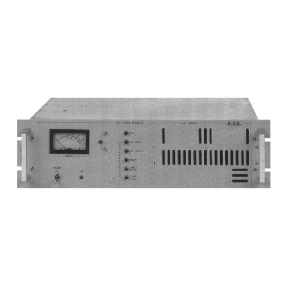
- Page 16 FRONT PANEL VIEW DESCRIPTION (FIG. 1) Power On/Off Switch Line A.C. Line Indicator Alarms Leds indicating the PJ250-NV's alarms status Grid Air duct grid Meter Analog meter used to monitor the operating parameters of the amplifier Meter Selector Selector to monitor parameters:...
- Page 17 PJ250-NV Technical and Maintenance Manual F I G . 1 R.V.R. Elettronica S.r.l. (Bo) Pag. 17...
- Page 18 PJ250-NV Technical and Maintenance Manual REAR PANEL VIEW DESCRIPTION (FIG. 2) Forced Ventilation R.F. Input R.F. Input Connector ("N" type) D.C. Fuse 1-2 Protection Fuse for R.F. Module A.C. Line for Exciter A.C. Power Line for Exciter Mains Voltage A.C. Power Line for Amplifier Voltage Changer and Fuse block and line voltage selector.
- Page 19 PJ250-NV Technical and Maintenance Manual F I G . 2 R.V.R. Elettronica S.r.l. (Bo) Pag. 19...
- Page 20 PJ250-NV Technical and Maintenance Manual TOP VIEW DESCRIPTION (PHOTO 1) ....Alarms Card ....Transformer ....R.F. Power Amplifier ....Low Pass Filter ....Directional Coupler R.V.R. Elettronica S.r.l. (Bo) Pag. 20...
- Page 21 PJ250-NV Technical and Maintenance Manual P H O T O 1 R.V.R. Elettronica S.r.l. (Bo) Pag. 21...
- Page 22 PJ250-NV Technical and Maintenance Manual DOWN VIEW DESCRIPTION (PHOTO 2) ....Transformer ....Switching Power Supply 1 ....Switching Power Supply 2 R.V.R. Elettronica S.r.l. (Bo) Pag. 22...
- Page 23 PJ250-NV Technical and Maintenance Manual P H O T O 2 R.V.R. Elettronica S.r.l. (Bo) Pag. 23...
- Page 24 PJ250-NV Technical and Maintenance Manual F I G . 3 R.V.R. Elettronica S.r.l. (Bo) Pag. 24...
- Page 25 PJ250-NV Technical and Maintenance Manual T A B L E C RECOMMENDED TEST EQUIPMENT INSTRUMENT MODEL SPECIFICATION Coaxial Load Resistor Bird Power Rating 300W continuous Mod. 8173 Wattmeter Bird Power Range: 100mW to 10KW Mod. 43 using Bird Plug-in-Elements Frequency Range: 0.45 to...
- Page 26 INSTALLATION OPERATIONS 3.1 UNPACKING This chapter contains necessary information for the preliminary checks and installation of the PJ250-NV. 3.2 UNPACKING Unpack the amplifier and, before any other operation, check that the amplifier isn’t damaged and that all controls on the front and rear panel are in good condition.
- Page 27 PJ250-NV. Continue this operation until a 250W output value is obtained. Check the reading of the internal wattmeter of the PJ250-NV with that of the external one (a discrepancy of about 10% is tolerable).
- Page 28 FIRST LEVEL MAINTENANCE 4.2 ORDINARY MAINTENANCE The only regular maintenance needed by the PJ250-NV, is the periodic replacement of the blowers, and the cleaning of dust filters and any dust accumulated inside the amplifier. The time between overhauling of the blowers depends upon several environmental factors, temperature, humidity, dust pollution etc.
- Page 29 PJ250-NV Technical and Maintenance Manual Disconnect connector J1 on the switching card. Unscrew the two fixing screw of D1 and U1 devices, placed on the heat-sink. Unscrew the fixing screws of the switching card. Remove the card. NOTE: During replacement of broken devices it's necessary to pay...
- Page 30 PJ250-NV Technical and Maintenance Manual Remove the stop nut of the R.F. Test -40dB Connector (8 Fig.2). Take note of the position of the four wires going out of the directional coupler and unsolder them. Extract the Directional Coupler. 4.8 TRANSFORMER REPLACEMENT Open the top and bottom covers.
- Page 31 PJ250-NV Technical and Maintenance Manual C H A P T E R 5 INTERNAL ADJUSTMENTS 5.1 POWER SUPPLY ADJUSTMENT No adjustments are needed after this board has been changed. 5.2 R.F. SECTION ADJUSTMENT No adjustment is required inside the R.F. section because it’s a factory adjusted module;...
- Page 32 PJ250-NV Technical and Maintenance Manual Place the FWD/RFL PWR selector (6 Fig.1) to the FWD position. Adjust trimmer R9 placed on the directional coupler for the same reading on the PJ250-NV’s meter is obtained. Switch off the amplifier. SETUP 3 Connect a dummy load 25 Ohm 500W (or 2 dummy load 50 Ohm 250W in parallel) with a through wattmeter (e.g.
- Page 33 (SETUP 4). Adjust the output power of the exciter to obtain a reading of 25W of reflected power on the external wattmeter and the PJ250-NV’s meter. Adjust the trimmer, R7, placed on the Alarms card until the S.W.R.
- Page 34 PJ250-NV’s meter. Increase the output power of the exciter again until a reading of 270W on the PJ250-NV’s meter is obtained. Adjust the trimmer, R21, placed on the Alarms card until the over- drive protection is activated, and the OVER DRIVE led lights up with immediate shutdown of the amplifier.
- Page 35 PJ250-NV Technical and Maintenance Manual INDICE Istruzioni Preliminari ed Informazioni di Garanzia Pag. 37 Regole di Sicurezza Pag. 39 CAPITOLO 1 Descrizione Generale Pag. 42 Specifiche Elettriche (Tabella A) Pag. 44 Specifiche Dimensionali e Ambientali (Tabella B) Pag. 45 CAPITOLO 2 Descrizione Elettrica Pag.
- Page 36 PJ250-NV Technical and Maintenance Manual Switching Power Supply Pag. 81 Directional Coupler Card Pag. 85 Alarms Card Pag. 89 R.V.R. Elettronica S.r.l. (Bo) Pag. 36...
- Page 37 PJ250-NV Technical and Maintenance Manual ISTRUZIONI PRELIMINARI E INFORMAZIONI DI GARANZIA Prego osservare le necessarie precauzioni di sicurezza quando si usa questa apparecchiatura. Questa macchina presenta al suo interno correnti pericolose e alte tensioni. Questo manuale è stato scritto per dare una guida generale per coloro che hanno necessità...
- Page 38 PJ250-NV Technical and Maintenance Manual La garanzia entrerà in vigore dalla data di fattura per il periodo di garanzia di costruzione. La garanzia di 12 mesi è riferita a qualsiasi prodotto R.V.R., mentre su prodotti quali transistors, Mos-Fet e valvole per finali vale la garanzia della casa costruttrice di tali dispositivi.
- Page 39 La R.V.R. ELETTRONICA s.r.l. non sarà responsabile per lesioni o danni risultanti da procedure improprie o dall'uso di personale inesperto o non correttamente addestrato all'adempimento di tali mansioni.
- Page 40 PJ250-NV Technical and Maintenance Manual T r a t t a m e n t o d e g l i s h o c k e l e t t r i c i 1) Se la vittima ha perso conoscenza seguire i principi di primo soccorso riportati nei punti A-B-C.
- Page 41 PJ250-NV Technical and Maintenance Manual PRIMO-SOCCORSO Il personale impegnato nell’installazione, nel funzionamento, nella manutenzione o assistenza di questo dispositivo ha la necessità di avere familiarità con la teoria e le pratiche di primo soccorso. La relazione seguente non rappresenta una guida completa delle procedure di primo soccorso, ma è...
- Page 42 1.2 DESCRIZIONE ELETTRICA Il PJ250-NV è un amplificatore di potenza sulla banda 87.5-108 MHz (è disponibile anche la versione O.I.R.T. 66-75 MHz) con una potenza in uscita di oltre 250W continui su tutta la banda, e con un livello di pilotaggio di circa 20W.
- Page 43 PJ250-NV Technical and Maintenance Manual anomalia . A distanza di circa 90 secondi la protezione riabilita l’apparecchiatura salvo la persistenza dell’anomalia. In tal caso la procedura si ripete quattro volte al termine della quale l’apparato rimane interdetto per 15 min., scaduti i quali se l’anomalia dovesse persistere si ha un nuovo ciclo di 4 interventi che una volta conclusi determinano il definitivo arresto dell’apparecchiatura.
- Page 44 PJ250-NV Technical and Maintenance Manual T A B E L L A A SPECIFICHE ELETTRICHE Alimentazione A.C. 100-130V, 50-60Hz 198-250V, 50-60Hz Raffreddamento Ventilazione Forzata Frequenza di Lavoro da 87.5 a 108 MHz (altre frequenze su richiesta) Potenza d'Uscita Max. 300W, Tip. 250 W Potenza di Pilotaggio R.F.
- Page 45 PJ250-NV Technical and Maintenance Manual T A B E L L A B SPECIFICHE DIMENSIONALI E AMBIENTALI Dimensioni del Cabinet 439.00 mm (17.28") L 129.00 mm (5.080") A 341.50 mm (13.44") P Dimensioni del Pannello 483.00 mm (19.00") L 132.50 mm (5.170") A Temperatura di Lavoro da -10°C a 50°C...
- Page 46 PJ250-NV Technical and Maintenance Manual C A P I T O L O 2 DESCRIZIONE ELETTRICA 2.1 INTRODUZIONE Questa sezione descrive in maniera complessiva la teoria di funzionamento del PJ250-NV. Per comodità descrittiva l’apparato è stato suddiviso in sottoinsiemi che saranno discussi in maniera approfondita di seguito.
- Page 47 PJ250-NV Technical and Maintenance Manual 2.5 LOW PASS FILTER Questo dispositivo (4 Foto 1) è contenuto all’interno di un contenitore metallico fissato sul dissipatore del modulo R.F.. Grazie alla presenza di questo filtro passa-basso si ottiene una riduzione dei segnali armonici di oltre 75 dB.
- Page 48 PJ250-NV Technical and Maintenance Manual D E S C R I Z I O N E D E L L A V I S T A D E L P A N N E L L O F R O N T A L E (FIG.
- Page 49 PJ250-NV Technical and Maintenance Manual F I G . 1 R.V.R. Elettronica S.r.l. (Bo) Pag. 49...
- Page 50 PJ250-NV Technical and Maintenance Manual D E S C R I Z I O N E D E L L A V I S T A D E L P A N N E L L O P O S T E R I O R E ( F I G .
- Page 51 PJ250-NV Technical and Maintenance Manual F I G . 2 R.V.R. Elettronica S.r.l. (Bo) Pag. 51...
- Page 52 PJ250-NV Technical and Maintenance Manual D E S C R I Z I O N E D E L L A V I S T A D A L L ' A L T O ( F O T O 1 ) ....
- Page 53 PJ250-NV Technical and Maintenance Manual FOTO 1 R.V.R. Elettronica S.r.l. (Bo) Pag. 53...
- Page 54 PJ250-NV Technical and Maintenance Manual D E S C R I Z I O N E D E L L A V I S T A I N F E R I O R E ( F O T O 2 ) ....
- Page 55 PJ250-NV Technical and Maintenance Manual FOTO 2 R.V.R. Elettronica S.r.l. (Bo) Pag. 55...
- Page 56 PJ250-NV Technical and Maintenance Manual F I G . 3 R.V.R. Elettronica S.r.l. (Bo) Pag. 56...
- Page 57 PJ250-NV Technical and Maintenance Manual T A B E L L A C STRUMENTAZIONE CONSIGLIATA PER I TEST STRUMENTO MODELLO SPECIFICHE Coaxial Load Resistor Bird Power Rating 300W continuous Mod. 8173 Wattmeter Bird Power Range: 100mW to 10KW Mod. 43 using Bird Plug-in-Elements Frequency Range: 0.45 to...
- Page 58 OPERAZIONI PER L’INSTALLAZIONE 3.1 INTRODUZIONE Questo capitolo contiene informazioni necessarie l’installazione ed il controllo preliminare del PJ250-NV. 3.2 DISIMBALLAGGIO Togliere dall’imballo l’apparecchiatura prima iniziare qualsiasi operazione, controllare che l’apparato non abbia subito danni durante il trasporto, e che quindi tutti i comandi presenti sul pannello anteriore e posteriore siano perfettamente funzionanti.
- Page 59 Continuare questa operazione fino a raggiungere una potenza d’uscita di 250W. Verificare l’esattezza della potenza d’uscita indicata dallo strumento del PJ250-NV con il wattmetro passante, considerando che la misura può essere affetta da errore dovuto allo strumento fino ad un massimo del 10%.
- Page 60 PRIMO LIVELLO DI MANUTENZIONE 4.3 MANUTENZIONE ORDINARIA L’unica manutenzione di cui necessita il PJ250-NV è la periodica sostituzione dei ventilatori e relativa pulizia da tracce di polvere eventualmente accumulate al suo interno. Tale periodicità è funzione delle condizioni di funzionamento della macchina, temperatura ambiente, livello di polvere nell’aria, umidità.
- Page 61 PJ250-NV Technical and Maintenance Manual Questa sezione contiene le informazioni pratiche per la sostituzione dei vari moduli dell’amplificatore PJ250-NV. N.B. PER RIMONTARE LE PARTI COMPONENTI L’AMPLIFICATORE E’ SUFFICIENTE ESEGUIRE LE OPERAZIONI NELLA SEQUENZA INVERSA. 4.5 SOSTITUZIONE DEL POWER SUPPLY Togliere il coperchio inferiore della macchina.
- Page 62 PJ250-NV Technical and Maintenance Manual Svitare le viti che fissano il filtro al dissipatore della sezione R.F.. Estrarre il filtro. 4.8 SOSTITUZIONE DELL’ACCOPPIATORE DIREZIONALE Togliere il coperchio superiore della macchina. Disconnettere il connettore d'ingresso SMA. Svitare le viti che fissano il connettore "N" d’uscita al retro dell'amplificatore.
- Page 63 PJ250-NV Technical and Maintenance Manual CAPITOLO 5 TARATURA 5.1 TARATURA DEL POWER SUPPLY Nessuna taratura è necessaria dopo la sostituzione di questa scheda. 5.2 TARATURA DELLO STADIO R.F. Nessuna taratura è normalmente necessaria su questo stadio, nel caso in cui siano necessarie tarature sullo stadio R.F., inviare la macchina alla casa costruttrice.
- Page 64 250W sul wattmetro esterno. Posizionare il selettore FWD/RFL PWR nella posizione FWD. Agire sul trimmer R9 posto sull’accoppiatore direzionale fino ad ottenere la stessa lettura sullo strumento del PJ250-NV. Spegnere le macchine. SETUP 3 Collegare, ora, un carico fittizio 25 Ohm 500W (oppure due carichi da 50 Ohm 250W in parallelo tra loro) con in serie un wattmetro passante (es.
- Page 65 PJ250-NV Technical and Maintenance Manual Ripetere l’intera sequenza operazioni verificare correttezza della taratura del trimmer R4. B) TARATURA DELLA PROTEZIONE DI R.O.S. SETUP 4 Collegare, ora, un carico fittizio 25 Ohm 500W (oppure due carichi da 50 Ohm 250W in parallelo tra loro) con in serie un wattmetro passante predisposto per la lettura della potenza riflessa (SETUP 4).
- Page 66 (es. BIRD mod.43) come mostrato nel SETUP 5. Regolare l’eccitatore per ottenere una lettura di 250W sul wattmetro passante esterno e sullo strumento interno del PJ250-NV. Aumentare ancora la potenza dell’eccitatore fino ad avere una potenza in uscita dal PJ250-NV di 270W.
- Page 67 PJ250-NV Technical and Maintenance Manual A P P E N D I X A C I R C U I T D I A G R A M S , L A Y O U T S A N D B I L L S O F M A T E R I A L This section contains circuit diagrams, layouts and bills of material of the modules which composing the equipment.
- Page 68 PJ250-NV Technical and Maintenance Manual WIRING DIAGRAM R.V.R. Elettronica S.r.l. (Bo) Pag. 68...
- Page 69 PJ250-NV Technical and Maintenance Manual R.F. POWER AMPLIFIER CircuitDiagram Pag. 70 Bill of Materials Pag. 71 CoponentLayout Pag. 73 R.F. POWER AMPLIFIER Schema Elettrico Pag. 70 Lista dei Componenti Pag. 71 Piano di Montaggio Pag. 73 R.V.R. Elettronica S.r.l. (Bo)
- Page 70 PJ250-NV Technical and Maintenance Manual R.V.R. Elettronica S.r.l. (Bo) Pag. 70...
- Page 71 PJ250-NV Technical and Maintenance Manual R.F. Power Amplifier Bill Of Materials Page 1 Item Quantity Reference Part Description Part Order Code ____________________________________________________________________________________________________ R5,R8,R10, 2.2* RESISTOR 1/2W 5% RSC1/2JH02,2 R14,R16,R18 R9,R17 RESISTOR 1/4W 5% RSC1/4JH0012 R4,R7,R11, RESISTOR 1/2W 5% RSC1/2JH0012 R13,R15,R19...
- Page 72 PJ250-NV Technical and Maintenance Manual R.F. Power Amplifier Bill Of Materials Page 2 Item Quantity Reference Part Description Part Order Code ____________________________________________________________________________________________________ ST11,ST12, STRIP LINE STRIP LINE ST13,ST14, ST15,ST16 R.V.R. Elettronica S.r.l. (Bo) Pag. 72...
- Page 73 PJ250-NV Technical and Maintenance Manual R.V.R. Elettronica S.r.l. (Bo) Pag. 73...
- Page 74 PJ250-NV Technical and Maintenance Manual LOW PASS FILTER CircuitDiagram Pag. 75 Bill of Materials Pag. 76 CoponentLayout Pag. 77 LOW PASS FILTER Schema Elettrico Pag. 75 Lista dei Componenti Pag. 76 Piano di Montaggio Pag. 77 R.V.R. Elettronica S.r.l. (Bo)
- Page 75 PJ250-NV Technical and Maintenance Manual R.V.R. Elettronica S.r.l. (Bo) Pag. 75...
- Page 76 PJ250-NV Technical and Maintenance Manual Low Pass Filter Bill Of Materials Page 1 Item Quantity Reference Part Description Part Order Code ____________________________________________________________________________________________________ C19,C33 4p7FHQ HIGHT Q CAPACITOR CHQ4,7AJ500 10pFHQ HIGHT Q CAPACITOR CHQ100AJ500 C16,C17, 27pFUNELCO SILVER MICA CAPACITOR CSM270XK351 C20,C21,...
- Page 77 PJ250-NV Technical and Maintenance Manual R.V.R. Elettronica S.r.l. (Bo) Pag. 77...
- Page 78 PJ250-NV Technical and Maintenance Manual TRANSFORMER SUPPLY SECTION CircuitDiagram Pag. 79 Bill of Materials Pag. 80 TRANSFORMER SUPPLY SECTION Schema Elettrico Pag. 79 Lista dei Componenti Pag. 80 R.V.R. Elettronica S.r.l. (Bo) Pag. 78...
- Page 79 PJ250-NV Technical and Maintenance Manual R.V.R. Elettronica S.r.l. (Bo) Pag. 79...
- Page 80 PJ250-NV Technical and Maintenance Manual Transformer Supply Section Bill Of Materials Page 1 Item Quantity Reference Part Description Part Order Code ____________________________________________________________________________________________________ R1,R2 2K2 1% RESISTOR 1/4W 1% RSC1/4FK02,2 F6.3A FAST FUSIBILE FUS5X20RP6.3 F3,F4 FB20A FAST FUSIBILE FUS6X30RP20 FILCT FILTRO VDE CON C. TENS. CNTVDEMPCT VDE1 VDE FPAN.
- Page 81 PJ250-NV Technical and Maintenance Manual SWITCHING POWER SUPPLY CircuitDiagram Pag. 82 Bill of Materials Pag. 83 CoponentLayout Pag. 84 SWITCHING POWER SUPPLY Schema Elettrico Pag. 82 Lista dei Componenti Pag. 83 Piano di Montaggio Pag. 84 R.V.R. Elettronica S.r.l. (Bo)
- Page 82 PJ250-NV Technical and Maintenance Manual R.V.R. Elettronica S.r.l. (Bo) Pag. 82...
- Page 83 PJ250-NV Technical and Maintenance Manual Switching Power Supply Bill Of Materials Page 1 Item Quantity Reference Part Description Part Order Code ____________________________________________________________________________________________________ R5,R6 0.22$ RESISTOR 5W RAF005JH0,22 1K 1% RESISTOR 1/4W 1% RSM1/4FK0001 4K7 1% RESISTOR 1/4W 1% RSM1/4FK04,7 18K 1%...
- Page 84 PJ250-NV Technical and Maintenance Manual R.V.R. Elettronica S.r.l. (Bo) Pag. 84...
- Page 85 PJ250-NV Technical and Maintenance Manual DIRECTIONAL COUPLER CircuitDiagram Pag. 86 Bill of Materials Pag. 87 CoponentLayout Pag. 88 DIRECTIONAL COUPLER Schema Elettrico Pag. 86 Lista dei Componenti Pag. 87 Piano di Montaggio Pag. 88 R.V.R. Elettronica S.r.l. (Bo) Pag. 85...
- Page 86 PJ250-NV Technical and Maintenance Manual R.V.R. Elettronica S.r.l. (Bo) Pag. 86...
- Page 87 PJ250-NV Technical and Maintenance Manual Directional Coupler Bill Of Materials Page 1 Item Quantity Reference Part Description Part Order Code ____________________________________________________________________________________________________ R4,R7,R12 47 1% RESISTOR 1/4W 1% RSM1/4FH0047 R1,R2 RESISTOR 2W RSC002JH0047 R10,R11 RESISTOR 1/4W 5% RSC1/4JH0100 RESISTOR 1/2W 5%...
- Page 88 PJ250-NV Technical and Maintenance Manual R.V.R. Elettronica S.r.l. (Bo) Pag. 88...
- Page 89 PJ250-NV Technical and Maintenance Manual ALARMS CARD CircuitDiagram Pag. 90 Bill of Materials Pag. 91 CoponentLayout Pag. 93 ALARMS CARD Schema Elettrico Pag. 90 Lista dei Componenti Pag. 91 Piano di Montaggio Pag. 93 R.V.R. Elettronica S.r.l. (Bo) Pag. 89...
- Page 90 PJ250-NV Technical and Maintenance Manual R.V.R. Elettronica S.r.l. (Bo) Pag. 90...
- Page 91 PJ250-NV Technical and Maintenance Manual Alarms Card Bill Of Materials Page 1 Item Quantity Reference Part Description Part Order Code ____________________________________________________________________________________________________ R8,R10,R22 10 1% RESISTOR 1/4W 1% RSM1/4FH0010 47 1% RESISTOR 1/4W 1% RSM1/4FH0047 100 1% RESISTOR 1/4W 1% RSM1/4FH0100...
- Page 92 PJ250-NV Technical and Maintenance Manual Alarms Card Bill Of Materials Page 2 Item Quantity Reference Part Description Part Order Code ____________________________________________________________________________________________________ 22µF ELECTROLYTIC CAPACITOR CEA226BM350 C6,C8 33µF ELECTROLYTIC CAPACITOR CEA336BM350 100µF ELECTROLYTIC CAPACITOR CEA107BM350 220µH RF CHOKE IMP220UA RELE’1 RY12W-K RELAY 2 VIE 12V TAKAM.
- Page 93 PJ250-NV Technical and Maintenance Manual R.V.R. Elettronica S.r.l. (Bo) Pag. 93...
- Page 94 PJ250-NV Technical and Maintenance Manual © Copyright 1993 First Edition - December ’95 Created By D’Alessio D. & Morotti M. R.V.R. Elettronica S.r.l. (Bo) Via del Fonditore 2/2c - 40138 - Bologna (Italy) National: Phone 051/601.05.06 r.a. Fax 051/601.11.04 International: Phone +39 51-601.05.06 Fax +39 51-601.11.04 Printed and bound in Italy.
- Page 95 PJ250 APPENDIX Description RVR Code Vers. Page Power Supply PSSW2812B Appendix Rev. 0.1 - 03/09/02...
- Page 96 PJ250 Pagina lasciata intenzionalmente in bianco Rev. 0.1 - 03/09/02 Appendix...
- Page 97 PJ250 Technical Appendix Rev. 0.1 - 03/09/02 PSSW2812B - 1 / 4...
- Page 98 PJ250 2 / 4 - PSSW2812B Rev. 0.1 - 03/09/02 Technical Appendix...
- Page 99 PJ250 POWER SUPPLY Bill Of Materials Page1 Item Q.ty Reference Part _____________________________________________________________________________________________________ 4n7UF C2,C3,C9,C10,C11 CP.1uF CM.1UF CT1/35 C6,C8,C17,C19,C26 CD.1uF C7,C23,C24,C25 EKR220/63 C12,C13,C14,C15,C16 1000/50 CM.22uF CAP NP CD10KPF C22,C31 CD1KPF/100 220/35 4.7uF CD1KPF 100/25 13V/1W DZ2,DZ4 3V3/0.5 15V/1W D1,D3 11DQ06 MBR1660 BL02 N.C.
- Page 100 PJ250 Pagina lasciata intenzionalmente in bianco This page was intentionally left blank 4 / 4 - PSSW2812B Rev. 0.1 - 03/09/02 Technical Appendix...
Need help?
Do you have a question about the PJ250-NV and is the answer not in the manual?
Questions and answers