Table of Contents
Advertisement
Quick Links
Advertisement
Table of Contents

Related Manuals for Proconx GCP-MG


Summary of Contents for Proconx GCP-MG
- Page 1 GCP-MG GCP Modbus gateway User manual Edition 1.2 UMGCPMG-2201...
- Page 2 Pty Ltd. Modbus is a registered trademark of Schneider Automation Inc. All other product and brand names mentioned in this document may be trademarks or registered trademarks of their respective owners.
-
Page 3: Table Of Contents
IP setup using a terminal program like HyperTerminal ........18 Temporarily changing the IP settings on your PC ..........19 5 Web browser based management ................. 21 Connecting to the GCP-MG ................21 Monitoring and diagnostic ................22 Device status ....................22 Modbus connection status ................. - Page 4 A Specifications ......................45 Dimensions ......................47 References ........................49 Glossary ........................51 Index .......................... 53 Figures 2.1 Location of connectors ..................5 2.2 Gateway operation ....................7 3.1 CAN bus topology ....................12 5.1 Device management and configuration via the web browser ......21 5.2 Overview page ....................
-
Page 5: Important User Information
• Apply appropriate personal protective equipment and follow safe electrical practices. • Turn off all power supplying the equipment in which the GCP-MG is to be installed before installing, wiring or removing the GCP-MG. • Always use a properly rated voltage sensing device to confirm that power is off. -
Page 6: Document Conventions
Document conventions Throughout this manual we use the following symbols and typefaces to make you aware of safety or other important considerations: Indicates a potentially hazardous situation that, if not avoided, could result in death or serious injury. Indicates a potentially hazardous situation that, if not avoided, could result in damage to equipment. -
Page 7: Introduction
Woodward’s GCP-30 Series Genset Controls and LS 4 Circuit Breaker Controls with Modbus networks. The GCP-MG gateway has been developed in cooperation with Woodward to ensure the highest possible degree of interoperability with Woodward equipment. The gateway features CAN, serial RS-232 and RS-485 ports as well as an Ethernet port and can be mounted on a DIN rail. -
Page 8: Features
• Remote control & monitoring • Data logging Features The GCP-MG gateway provides the following key features: • Modbus/TCP protocol (Ethernet) • Modbus RTU protocol (either RS-232 or RS-485, software configurable) • Interfaces with up to 16 GCP-30 controls and up to 8 LS 4 controls •... -
Page 9: Quick Start Checklist
Introduction Quick start checklist • Read this set of instructions properly and in its entirety. • Mount the unit. • Connect the power. Do not connect yet CAN bus or serial ports. • Configure the Ethernet communications settings with a web browser (using an Ethernet crossover cable) or with a terminal program like HyperTerminal (using a null modem cable) •... - Page 10 This page intentionally left blank UMGCPMG-2201...
-
Page 11: Description
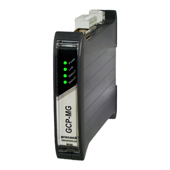
Modbus/CAN status LED Power terminals RS-485 Modbus terminals CAN connector LED indicators Four LEDs located at the front panel indicate the status of the GCP-MG. The LEDs assist maintenance personnel in quickly identifying wiring or communication errors. UMGCPMG-2201... -
Page 12: Principles Of Operation
CAN bus. All GCP-30 and LS 4 units transmit multiplexed data values which the GCP-MG stores in its internal data tables. A GCP-30 for example sends a new value every 100 ms, a LS 4 every 200 ms. -
Page 13: Gateway Operation
Description Figure 2.2: Gateway operation For remote control, a Modbus master writes control words to a dedicated internal data table which is then cyclically sent to the corresponding GCP-30 or LS 4 unit. One remote control data table is processed every 100 ms. This makes the remote control update cycles depend on the number of units enabled for remote control. - Page 14 This page intentionally left blank UMGCPMG-2201...
-
Page 15: Installation
Regulatory notes 1. The GCP-MG is suitable for use in non-hazardous locations only. 2. The GCP-MG is not authorized for use in life support devices or systems. 3. Wiring and installation must be in accordance with applicable electrical codes in accordance with the authority having jurisdiction. -
Page 16: Din Rail Mounting And Removal
DIN rail mounting and removal The GCP-MG gateway is designed to be mounted on a 35 mm DIN rail according to DIN/ EN 50022. The enclosure features a 35 mm profile at the back which snaps into the DIN rail. -
Page 17: Powering The Gcp-Mg
• Make sure there is sufficient air ventilation and clearance to other devices mounted next to the unit. • Observe applicable local regulations like EN60204 / VDE0113. Powering the GCP-MG Before connecting power please follow the rules in the section called “Safety Precau- tions” and the section called “Before connecting anything”. -
Page 18: Wiring The Rs-485 Modbus Interface
Figure 3.1: CAN bus topology Wiring the RS-485 Modbus interface The RS-485 Modbus interface is used for integrating the GCP-MG into a two-wire Modbus over Serial Line network. The use of the RS-485 interface must be configured using the web interface (See the section called “Configuring serial line Modbus”). The GCP-MG is a Modbus slave device. -
Page 19: Wiring The Rs-232 Modbus Interface
Modbus master device instead of RS-485. The use of the RS-232 interface must be configured using the web interface (See the section called “Configuring serial line Modbus”). The GCP-MG is a Modbus slave device. The RS-232 Modbus connector is a male 9-pin D-sub type located at the bottom side of the mounted unit (refer to Figure 2.1, “Location of connectors”... -
Page 20: Connecting Ethernet
• The shield must not be connected to the GND pin. To connect the GCP-MG to a PC (Personal Computer) or any other device with data terminal equipment (DTE) pinout you need a null-modem or cross-over cable. -
Page 21: Connecting To The Diagnostic Port
• The shield must not be connected to the GND pin. To connect the GCP-MG to a PC (Personal Computer) or any other device with data terminal equipment (DTE) pinout you need a null-modem or cross-over cable. - Page 22 This page intentionally left blank UMGCPMG-2201...
-
Page 23: Ethernet & Ip Configuration
“Temporarily changing the IP settings on your PC”). In order to connect to the GCP-MG via TCP/IP, your PC must be on same IP subnet as the gateway. In most situations this means that the first three numbers of the IP address have to be identical. -
Page 24: Ip Setup Using A Terminal Program Like Hyperterminal
IP setup using a terminal program like HyperTerminal 1. Connect a null modem RS-232 cable between your PC and the GCP-MG's diagnostic port. 2. In Windows XP, click Start, point to All Programs, point to Accessories, point to Communications, and then click HyperTerminal. -
Page 25: Temporarily Changing The Ip Settings On Your Pc
This method involves manually assigning an IP address to your PC in the same subnet as the gateway. The default subnet of the gateway is 169.254.0.0/16. 1. Connect the GCP-MG to your Ethernet network. 2. On a Windows PC, open the Control Panel and double-click on Network Connections. - Page 26 8. Click Configuration… and then Ethernet & IP in the menu on the left side of the page. 9. Enter the IP address, subnet mask, and gateway address assigned to your GCP-MG, then click Save. 10.Restore your computer’s original settings.
-
Page 27: Web Browser Based Management
Once you made sure that your PC is configured to be on the same subnet as the GCP-MG, start your web browser. In the address box, type the IP address of your device (169.254.0.10 is the default), and then press Enter. (See Chapter 4, Ethernet & IP... -
Page 28: Monitoring And Diagnostic
Use the menu bar shown on the left side to navigate the different pages. In order to connect to the GCP-MG via TCP/IP, your PC must be on same IP subnet as the gateway. In most situations this means that the first three numbers of the IP address have to be identical. -
Page 29: Modbus Connection Status
CAN’s built in fault confinement mechanism has set the node to bus-off state due to excessive errors on the CAN bus. This alarm indicates a wiring error. The GCP-MG will not transmit or receive any message on the CAN bus once entered this state. The device needs to be manually restarted on order to recover from this fault. -
Page 30: Can Communication Status
Rx time-outs (Modbus/TCP) A counter that increments if the master connection has timed out. Subsequently the connection is terminated by the GCP-MG. A time-out occurs if no Modbus request is received from a connected client within a 10 second period. -
Page 31: Can Communication Status Page
The GCP-30 or LS 4 control is cyclically updating data. WAIT The presence of a GCP-30 or LS 4 unit has been detected however the GCP-MG is currently waiting to receive a complete data set. It takes approximately between 2.3 and 3 seconds to receive a full data set from the GCP-30 and approximately 10 seconds from the LS 4. -
Page 32: Finding The Firmware Version And Serial Number
The firmware version that is installed on the GCP-MG. Serial number The serial number of the GCP-MG. The serial number is specific to your device. Configuring and commissioning The configuration pages are accessed by clicking on the Configuration… menu entry on the menu bar which then expands a configuration sub-menu. -
Page 33: Configuring Ethernet And Ip
Web browser based management Configuring Ethernet and IP Select the Configuration→Ethernet & IP sub-menu from the menu bar to open the Ethernet and IP settings which are shown below: Figure 5.6: Ethernet and IP settings page The following Ethernet parameters are shown: MAC address The device' unique MAC address. -
Page 34: Configuring Gcp-30 And Ls 4 Modbus Access
Modbus master activity takes place (See Monitored Control). Before being able to use Remote Control, please check that the GCP-30 unit has been parameterized accordingly, otherwise the messages sent by the GCP-MG are ignored by the GCP-30. Refer to chapter Interface in your GCP-30 Series Genset Control manual. For Remote... -
Page 35: Configuring Serial Line Modbus
If a Modbus master fails to do this within a certain time limit, the GCP-MG will trigger an Interface error X1X5 alarm on the GCP-30. For Monitored Control to be effective, GCP-30 Parameter 121 Supervision X1X5 must be turned on. -
Page 36: Remote Restarting The Device
Baud rate 9600 and 19200 are the most common baud rates for Modbus. 19200 is the default setting. Data bits Only 8 data bits can be selected here which is a requirement for RTU. Stop bits Can be configured to be 1 or 2. The Modbus standard mandates that 2 stop bits are configured when using no parity. - Page 37 Web browser based management After a remote restart a Watchdog reset alarm is shown on the device' home page. This is a side-effect of the remote restart procedure and the alarm shall be ignored and cleared. UMGCPMG-2201...
- Page 38 This page intentionally left blank UMGCPMG-2201...
-
Page 39: Modbus Data Reference
This chapter describes how GCP-30 and LS 4 data values are organized in logical blocks and accessed via Modbus. The GCP-MG supports the Modbus function codes 03, 04, 06 and 16. A maximum of 100 16-bit words can be requested with Modbus command 04. This makes it possible to read the complete data set of a GCP-30 or LS 4 unit with a single Modbus transaction. -
Page 40: Gcp-30 Mux Data Table 3:0001
Unit Modbus Modbus read Modbus write Modbus floating point CAN ID slave ID address range address range address range LS 4 #6 3:0001-3:0100 4:0003 3:1001-3:1034 LS 4 #7 3:0001-3:0100 4:0003 3:1001-3:1034 LS 4 #8 3:0001-3:0100 4:0003 3:1001-3:1034 Table 6.2: Modbus slave ID relationship A standard LS 4 occupies only the range from 3:0001 to 3:0029. -
Page 41: Modbus Addresses For Gcp-30 Mux Values
GCP-30 is not present on the CAN bus. For the GCP-30 MUX data table, the GCP-MG acts as a transparent gateway between the GCP-30 unit and the Modbus. Except for the device status register at Modbus address 0001, it does not perform any modification to the representation of the data values. - Page 42 Block Modbus GCP-30 GCP-30 GCP-30 manual designator address word no. 0029 Current actual real power in the system 0030 Number of participants on the CAN bus 0031 High byte: Mains status, Low byte: Generator status 0032 10/1 Exponents 0033 10/2 Bus bar frequency 0034 10/3...
-
Page 43: Allocation With Options Sb03 And Sc06
Modbus data reference Block Modbus GCP-30 GCP-30 GCP-30 manual designator address word no. 0071 - Not used by a standard GCP-30, reserved for options, future expansion or 0100 custom versions. See below for allocation by option SB03 and SC06. Table 6.4: Modbus addresses for GCP-30 MUX values If no response was obtained from the target GCP-30 unit, Modbus exception code 0B Gateway target device failed to respond is returned. -
Page 44: Modbus Addresses For Gcp-30 Floating Point Data Table
The floating point values are encoded in industry standard single-precision (32-bit) IEEE 754 format. The 32-bit floating point values are transmitted as pairs of two consecutive 16-bit registers in little-endian word order. Block Modbus GCP-30 GCP-30 GCP-30 manual designator Unit address word no. -
Page 45: Gcp-30 Remote Control Data Table 4:0001
If remote control is enabled, the three remote control words are sent cyclically to the respective GCP-30. They are also stored in the GCP-MG's memory and can be read back using Modbus function code 03 Read holding registers. -
Page 46: Modbus Addresses For Ls 4 Mux Values
LS 4 unit is not present on the CAN bus. For the LS 4 MUX data table, the GCP-MG acts as a transparent gateway between the LS 4 unit and the Modbus. Except for the device status register at Modbus address 0001, it does not perform any modification to the representation of the data values. -
Page 47: Ls 4 Floating Point Data Table 3:1001
Modbus data reference Block Modbus LS 4 MUX LS 4 word LS 4 manual designator address 0030 - Not used by a standard LS 4, reserved for future expansion or custom ver- 0100 sions. Table 6.8: Modbus addresses for LS 4 MUX values If no response was obtained from the target LS 4 unit, Modbus exception code 0B Gateway target device failed to respond is returned. -
Page 48: Ls 4 Remote Control Data Table 4:0001
If Remote Control is enabled, the three remote control words are sent cyclically to the respective LS 4. They are also stored in the GCP-MG's memory and can be read back using Modbus function code 03 Read holding registers. -
Page 49: Decommissioning
1. Ensure that the system power and external supplies have been turned off. 2. Disconnect power supply plug. 3. Disconnect all I/O cables. 4. Remove the GCP-MG from the DIN rail following the procedure described in the section called “DIN rail mounting and removal”. Disposal This product must be disposed of at a specialized electronic waste recycling facility. - Page 50 This page intentionally left blank UMGCPMG-2201...
-
Page 51: A Specifications
Specifications Appendix A. S pecifications Product name GCP-MG Interfaces Ethernet Serial ports 1 for Modbus (either RS-232 or RS-485, software configurable) 1 for diagnostics (RS-232) User interface LED indicators Power (green), Ethernet link (green), 2 status (bi-color red/green) Monitoring & configuration... - Page 52 Isolation 1.5 kV galvanic Speed 10 Mbit/s Max. cable length 100 m (328 ft) Ethernet frame types 802.3 Protocols Modbus/TCP slave, HTTP , IP , TCP , ARP Concurrent connections 2 Modbus/TCP , 2 HTTP Power supply Connector 3.81 mm 2-pin pluggable terminal block header Voltage 10-30 V DC Current...
-
Page 53: Dimensions
Specifications Dimensions 120.0 mm 22.5 mm 4.72 in 0.89 in Figure A.1: Enclosure dimensions UMGCPMG-2201... - Page 54 This page intentionally left blank UMGCPMG-2201...
-
Page 55: References
References References [GCP30] Woodward Governor Company, "GCP-30 Series Packages Genset Control — Configuration", Manual 37365A, February 2007 [LS4] Woodward Governor Company, "LS 4 Circuit Breaker Control — Manual", Manual 37105A, May 2004 UMGCPMG-2201... - Page 56 This page intentionally left blank UMGCPMG-2201...
-
Page 57: Glossary
Glossary Glossary Electromagnetic compatibility 10BASE-T Electromagnetic interference 10 Mbit/s twisted pair Ethernet standard. Standardized in IEEE 802.3i APIPA Electrostatic discharge. ESD can damage Automatic Private IP Addressing electronic equipment. IEEE Controller area network. Standardized in ISO Institute Electrical Electronics 11898. Engineers CiA DS-102 Standard for the pinout of CAN connectors... - Page 58 RS-422 See EIA-422. RS-485 See EIA-485. UL 94 Plastics flammability standard released by Underwriters Laboratories of the USA. UMGCPMG-2201...
-
Page 59: Index
Index Index electronic waste, 43 embedded web server, 21 EMC, 9 enclosure About, 26 DIN rail clip, 5 Accumulative connections, 24 front cover, 5 ACTIVE, 23 mounting, 10 APIPA, 17 red hook, 10 removal, 10 Ethernet, 14, 27 Baud rate, 30 settings, 27 Brown out reset, 22 exception codes, 34... - Page 60 values, 41 remote restart, 30 removal, 10 Replies, 24 Requests, 24 MAC address, 27 Reset to factory defaults, 23 MDEC, 37 restart, 30 Messages received, 25 RJ-45, 14 Messages sent, 25 RS-232, 14, 15 Modbus RS-485, 13 address range, 33 run-time faults, 22 exception codes, 34 Rx time-outs, 24...
- Page 61 Index WAIT, 25 Watchdog reset, 22 Watchdog reset alarm, 31 UMGCPMG-2201...
- Page 62 This page intentionally left blank UMGCPMG-2201...
- Page 63 Notes Notes UMGCPMG-2201...
- Page 64 This page intentionally left blank UMGCPMG-2201...
Need help?
Do you have a question about the GCP-MG and is the answer not in the manual?
Questions and answers