
Related Manuals for Proconx ESEPRO


Summary of Contents for Proconx ESEPRO
- Page 1 ESEPRO Profibus gateway for CANopen genset controls User manual Edition 1 UMESEPRO-2201...
- Page 2 Disclaimer proconX Pty Ltd makes no warranty for the use of its products, other than those expressly contained in the Company’s standard warranty which is detailed in the Terms and Conditions located on the Company’s Website. The Company assumes no responsibility for any errors which may appear in this document, reserves the right to change devices or specifications detailed herein at any time without notice, and does not make any commitment to update the information contained herein.
-
Page 3: Table Of Contents
Unpacking, handling and storage ................ 5 Before connecting anything ................. 5 DIN rail mounting and removal ................6 Mounting rules ....................6 Powering the ESEPRO ..................7 Wiring the Profibus interface ................7 Wiring the CAN interface ..................8 Connecting Ethernet .................... 9 4 Profibus configuration .................... - Page 4 Figures 2.1 Location of connectors ..................3 4.1 Commissioning the ESEPRO using Simatic Step 7’s HW Config tool ....11 4.2 Assigning station address using Step 7’s HW Config tool ........11 4.3 Example configuration of direct mapping with 4 Easygens using 6 Mux objects each ...........................
- Page 5 3.3 CAN bus connector pinout ..................9 3.4 Ethernet connector pinout .................. 10 5.1 CANopen Data Protocols ..................22 5.2 Relationship between Remote Control Word ID and DP-V1 Index ......29 6.1 CANopen Node-ID & COB-ID relationship ............33 6.2 Supported Data Protocols ................... 34 UMESEPRO-2201...
- Page 6 This page intentionally left blank UMESEPRO-2201...
-
Page 7: Important User Information
• Apply appropriate personal protective equipment and follow safe electrical practices. • Turn off all power supplying the equipment in which the ESEPRO is to be installed before installing, wiring or removing the ESEPRO. • Always use a properly rated voltage sensing device to confirm that power is off. -
Page 8: Document Conventions
Document conventions Throughout this manual we use the following symbols and typefaces to make you aware of safety or other important considerations: Indicates a potentially hazardous situation that, if not avoided, could result in death or serious injury. Indicates a potentially hazardous situation that, if not avoided, could result in damage to equipment. -
Page 9: Introduction
Woodward controls and is easy to configure using standard Profibus configuration tools like Simatic Manager. A single ESEPRO added to the CAN network will make all Visualisation Data of connected Woodward CANopen controls available without adding additional load to the CAN bus communication. -
Page 10: Features
• Gen set control • Remote control & monitoring • Data logging Features The ESEPRO gateway provides the following key features: • Supports Easygen-3000 Series (3500, 3400, 3200, 3100) • Supports Easygen-2000 Series • Supports Easygen-1000 Series • Supports LS-5 •... -
Page 11: Description
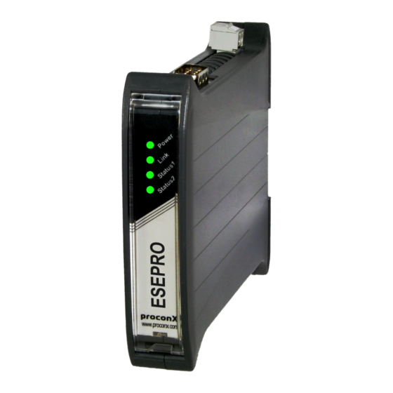
CAN bus connector LED indicators Four LEDs located at the front panel indicate the status of the ESEPRO. The LEDs assist maintenance personnel in quickly identifying wiring or communication errors. A LED test is exercised at power-up, cycling each LED off, green and then red for approximately 0.25 seconds. -
Page 12: Led Diagnostic Codes
The following table outlines the indicator condition and the corresponding status after the power-on self-test has been completed: Function Condition Indication Power Power No power applied to the device. Green Power supply OK Link Ethernet link No Ethernet link Green Ethernet link OK Status1 Device status... -
Page 13: Installation
Regulatory notes 1. The ESEPRO is suitable for use in non-hazardous locations only. 2. The ESEPRO is not authorized for use in life support devices or systems. 3. Wiring and installation must be in accordance with applicable electrical codes in accordance with the authority having jurisdiction. -
Page 14: Din Rail Mounting And Removal
DIN rail mounting and removal The ESEPRO gateway is designed to be mounted on a 35 mm DIN rail according to DIN/ EN 50022. The enclosure features a 35 mm profile at the back which snaps into the DIN rail. -
Page 15: Powering The Esepro
CAN port! A wrong polarity can cause high currents on the ground plane between the V- power supply pin and the ground pins of the non-isolated CAN port, which can cause damage to the device. Wiring the Profibus interface The Profibus interface connects the ESEPRO to a Profibus-DP master station. UMESEPRO-2201... -
Page 16: Wiring The Can Interface
Wiring the CAN interface The CAN interface connects the ESEPRO to the Woodward CANopen based controls. UMESEPRO-2201... -
Page 17: Connecting Ethernet
Do not connect the cable shield to the CAN_GND pins or the connector shell! Use an external chassis ground connection to terminate the shield. Connecting Ethernet The ESEPRO is equipped with an Ethernet interface for diagnostic and maintenance purposes. The Ethernet interface is not used in normal operation. The default IP address is 169.254.0.10. - Page 18 The following table describes the 10BASE-T Ethernet RJ-45 connector pinout: Signal Function Non-inverting transmit signal Inverting transmit signal Non-inverting receive signal Internal termination network Internal termination network Inverting receive signal Internal termination network Internal termination network Table 3.4: Ethernet connector pinout •...
-
Page 19: Profibus Configuration
Profibus configuration Chapter 4. Profibus configuration The ESEPRO gateway is configured using a Profibus configuration tool like Simatic Step 7’s HW Config. The required GSD file PROX0EAB.GSD can be downloaded from https:// www.proconx.com/esepro/gsd Install the GSD file according to the requirements of your Profibus configuration tool. -
Page 20: Mapping Of Woodward Devices Into The Process I/O
Mapping of Woodward devices into the process I/O The ESEPRO gateway is a modular Profibus slave device which is organised into virtual modules. Different type of virtual modules can be configured. Each of the types facilitate different methods of data transport. -
Page 21: Data Protocols From Easygen-3500 Manual
Profibus configuration Figure 4.4: Data Protocols from Easygen-3500 manual Input Power Av. Gen. Factor Wye Voltage Figure 4.5: Example how the Easygen-3000 Mux object 1 maps into the PLC iput area Once a Mux object module is inserted, it has to be parametrized with a COB-ID and the Mux number. -
Page 22: Indexed Mapping
Figure 4.6: Parameter assignment of a Mux object module The following module parameters can be configured: COB-ID of the TPDO which transmits the Data Protocol COB-ID Data Protocol Mux number (Data byte 0) of object to be mapped The I/O space of Profibus-DP is limited to 244 bytes and compared to the large amount of data available in a Woodward control only a relativley small number of data values can be mapped directly into the I/O space. -
Page 23: Generic Woodward Device Module
Profibus configuration Figure 4.7: Example configuration with 3 Easygens (Node-ID 1, 2 and 3) and 2 LS-5 (Node-ID 11 and 12) There are however applications where automatic linking is not practical and the link to a particluar Woodward device can be set using the following module parameters: CANopen Node-ID of the Woodward device. -
Page 24: Extract From Easygen Manual With Data Protocol 4103 J1939 Standard Visualization
Figure 4.8: Extract from Easygen manual with Data Protocol 4103 J1939 Standard Visualization UMESEPRO-2201... -
Page 25: J1939 Data Protocol Tpdo Configuration With Woodward Toolkit
Profibus configuration Use Woodward’s ToolKit to configure a second TPDO in the Easygen with protocol 4103 and set it to a unique COB-ID within the range 432 - 511 as shown below: Figure 4.9: J1939 Data Protocol TPDO configuration with Woodward ToolKit Then add a Generic Woodward device module with the following parameter assignment to your Profibus configuration: Node-ID = Parameter 8950 Node-ID of the Easygen... -
Page 26: Rpdo Profile
TPDO (Transmit PDO) channels. While the first TPDO channel is typically used for the Mux based visualisation data, the remaining TPDO channels can be configured application specific. The ESEPRO gateway supports reading application specific PDO messages using the RPDO module. - Page 27 Profibus configuration Configure the COB-ID to match the TPDO. Must be in the range COB-ID of 432 (1B0 ) to 511 (1FF UMESEPRO-2201...
- Page 28 This page intentionally left blank UMESEPRO-2201...
-
Page 29: Profibus Operation
Remote Control 00001 Figure 5.1: Organisation of data in Woodward controls Processing Data Protocol data through the ESEPRO gateway is more efficient and faster than using single parameter values because Data Protocol data is internally buffered and instantly available. All Woodward CANopen devices offer several Data Protocols which can be published via CANopen. -
Page 30: Addressing Of Woodward Canopen Devices
IKD 1 - external DIs/DOs 25 through 32 Enabled by default Table 5.1: CANopen Data Protocols For a Data Protocol to be available through the ESEPRO gateway, it must be enabled in the TPDO configuration of the Woodward CANopen device. Addressing of Woodward CANopen devices The individual Woodward devices on the CAN bus are identified by two different means. -
Page 31: Dp-V0 Indexed Data Mapping
Profibus operation To overcome this limitation the ESEPRO offers two distinct data transfer methods: • Profile style transfers using a small 7 byte request/reply buffer in the process I/O area • DP-V1 transfers using acyclic communication services. DP-V0 indexed data mapping The method of using indexed data mapping is similar to the method used by the Profidrive standard. -
Page 32: Message Sequence Chart For Reading The Three Generator Currents
ESEPRO Easygen control Cyclic PDO Q0 = 11 Wait until I0 = 11 I0 = 11 I3 = Generator current 1 Q0 = 12 Wait until I0 = 12 I0 = 12 I3 = Generator current 2 Q0 = 13... -
Page 33: Read Parameter
249 = SDO response time-out error 255 = PDO communication time-out error Parameter value if Status is 241, 242 or 244. Length is Status minus Value 240. ESEPRO Easygen control Q0 = 240 Q1,2 = 1752 I0 = 245 SDO request... -
Page 34: Write Parameter
Unless the Parameter ID is in the remote control range from 500 to 599 a CAN Interface password with the appropriate code level must be set before the parameter change is accepted by the Woodward control. ESEPRO Easygen control Q0 = 242... -
Page 35: Dp-V1 Functions
I1,2 = 1752 Figure 5.6: Message sequence chart for writing parameter ID 1752 "Gen. rated active power" DP-V1 functions The ESEPRO supports the following services for acyclic communication in the Profibus DP network: • Communication between class 1 master and slave (MS1): •... -
Page 36: Read Mux Objects
2 or 4, set to size of Remote Control Word which can be either 2 Length or 4 bytes 2 or 4, length of the read result in bytes Length Variable size field holding the read result Data ESEPRO Easygen control DP_Read Index = 103 Length = 2 SDO request SDO reply... -
Page 37: Write Remote Control Word
2 or 4, set to size of Remote Control Word which can be either 2 Length or 4 bytes Variable size field holding the remote control word content Data No interface password is required for writing to Remote Control Words. ESEPRO Easygen control DP_Write Index = 156 Length = 2 Byte 1,2 = 1... -
Page 38: Remote Control Examples
Remote Voltage Set- 110 4 V × 1 Easygen Analog Manager data point source [05.09] Remote Reset Alarm 122 2 Parameter ID of alarm Resetting specific alarms Remote Control Bit 16 541 141 2 0=off, 1=on LS-5 or Easygen Logics Manager command variable [04.59] Remote Control Bit 15 542 142 2... - Page 39 Profibus operation Request Data = 0002 Alarm reset Easygen 1. Set signal Index = 103 Length = 2 Request Data = 0010 2. Reset signal Index = 103 Length = 2 Request Data = 0000 Alarm reset requires generation of two rising edges which is achieved by first setting the command bit, clearing it again and then repeating this sequence.
- Page 40 Request Data = 1 Clear Remote Control Bit 1 on LS-5 Index = 156 Length = 2 Request Data = 0 UMESEPRO-2201...
-
Page 41: Configuration Of Connected Woodward Controls
Chapter 6. Configuration of connected Woodward controls The ESEPRO has been designed to keep the configuration effort required to connect the gateway with Woodward CANopen devices to a minimum. In most situations no additional configuration is necessary to get the ESEPRO communicating with an Easygen-3000 series control. - Page 42 CANopen Node-ID TPDO COB-ID dec TPDO COB-ID hex Table 6.1: CANopen Node-ID & COB-ID relationship Data Protocol of the Transmit PDOs The Data Protocol of the Transmit PDOs must be set according to the Woodward CANopen device used. The following tables shows the supported Data Protocols. Woodward CAN device Data protocol Mapped Object ID...
-
Page 43: Specific Information For Easygen-3000 Series Controls
Configuration of connected Woodward controls Specific information for Easygen-3000 series controls The most convenient way to configure the Easygen is using Woodward’s Toolkit software. Below are Toolkit screenshots of the relevant menus. Figure 6.1: "Configure interfaces" menu in Woodward Toolkit CAN interface From Woodward’s Toolkit software select the Configure CAN interface 1 page as shown below: Figure 6.2: "Configure CAN interface 1"... -
Page 44: Transmit Pdos
Transmit PDOs In order for the ESEPRO gateway to receive cyclic data updates from the Easygen, one of the five available Transmit PDOs (TPDO) must be configured. Typically Tranmsit PDO 1 is already pre-configured for that purpose, but any of the five TPDOs could be used for that purpose. -
Page 45: Specific Information For Ls-5 Controls
Configuration of connected Woodward controls All COB-IDs used in the CAN network must be unique. Please make sure that a COB-ID is only configured once. If TPDO or RPDO COB-ID entries are referring to an already used COB-ID, either disable that PDO or change its COB-ID. Specific information for LS-5 controls The LS-5 CANopen parameters are configured using Woodward’s Toolkit software. -
Page 46: Transmit Pdos
127 and a unique number in the network. Transmit PDOs In order for the ESEPRO gateway to receive cyclic data updates from the LS-5, one of the five available Transmit PDOs (TPDO) must be configured. Typically Tranmsit PDO 1 is already pre-configured for that purpose, but any of the five TPDOs could be used for that purpose. -
Page 47: Decommissioning
Decommissioning Chapter 7. Decommissioning Before disconnecting the ESEPRO unit please follow the rules in the section called “Safety Precautions”. Disconnecting 1. Ensure that the system power and external supplies have been turned off. 2. Disconnect power supply plug. 3. Disconnect all I/O cables. - Page 48 This page intentionally left blank UMESEPRO-2201...
-
Page 49: A Specifications
Specifications Appendix A. S pecifications Product name ESEPRO Interfaces Profibus 1 DP-Slave Ethernet 1 (diagnostics and firmware upgrade) User interface LED indicators Power (green), Ethernet link (green), 2 status (bi-color red/green) Monitoring Web browser based Diagnostic High availability features Watchdog supervision, brown-out detection... -
Page 50: Dimensions
Electrostatic discharge EN 61000-4-2 Radiated RF EN 61000-4-3 Fast transients EN 61000-4-4 Conducted RF EN 61000-4-6 Enclosure Material Self-extinguishing PC/ABS blend (UL 94-V0) Mounting 35 mm DIN rail (EN 60715) Classification / Type rating IP 20 / NEMA Type 1 Cooling Convection Environmental... -
Page 51: References
References References [PIG98] PROFIBUS Nutzerorganisation e.V., "Installation Guideline for PROFIBUS-DP/ FMS", Order No 2.112, Version 1.0, September 1998 UMESEPRO-2201... - Page 52 This page intentionally left blank UMESEPRO-2201...
-
Page 53: Glossary
Glossary Glossary DP-V0 DP-V0 is the basic stage of the Profibus DP communication protocol providing cyclic data exchange. DP-V1 Extension to Profibus DP protocol providing acyclic data transfer and alarms. Electromagnetic compatibility Electromagnetic interference Electrostatic discharge. ESD can damage 10BASE-T electronic equipment. - Page 54 Node A communications device on the network PC/ABS Polycarbonate-ABS. Widely used thermoplastic material. CANopen Process Data Object. Process data the device is either producing or consuming. Programmable Logic Controller Predefined Connection Set The CANopen Predefined Connection Set defines standard COB-IDs for PDOs and SDOs.
- Page 55 Notes Notes UMESEPRO-2201...
- Page 56 This page intentionally left blank UMESEPRO-2201...
Need help?
Do you have a question about the ESEPRO and is the answer not in the manual?
Questions and answers