Table of Contents
Advertisement
Quick Links
Advertisement
Table of Contents

Related Manuals for Proconx MBDC-200


Summary of Contents for Proconx MBDC-200
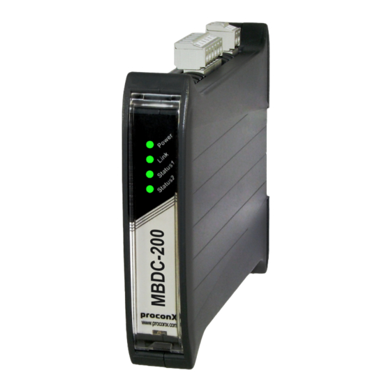
- Page 1 MBDC-200 Modbus Data Concentrator and Gateway User manual UMMBDC200-2201...
- Page 2 Pty Ltd. Modbus is a registered trademark of Schneider Automation Inc. All other product and brand names mentioned in this document may be trademarks or registered trademarks of their respective owners.
-
Page 3: Table Of Contents
IP setup using a terminal program like HyperTerminal ........12 Temporarily changing the IP settings on your PC ..........13 5 Web browser based management ................. 15 Connecting to the MBDC-200 ................15 Monitoring and diagnostic ................16 Device status ....................16 Modbus connection status ................. - Page 4 2.1 LED diagnostic codes .................... 4 3.1 Power supply connector pinout ................7 3.2 RS-485/RS-422 connector pinout ................7 3.3 Modbus RS-232 connector pinout ................ 8 3.4 Ethernet connector pinout ..................9 7.1 Modbus register addresses for MBDC-200 diagnostic data ......... 29 UMMBDC200-2201...
-
Page 5: Important User Information
• Apply appropriate personal protective equipment and follow safe electrical practices. • Turn off all power supplying the equipment in which the MBDC-200 is to be installed before installing, wiring or removing the MBDC-200. • Always use a properly rated voltage sensing device to confirm that power is off. -
Page 6: Document Conventions
Document conventions Throughout this manual we use the following symbols and typefaces to make you aware of safety or other important considerations: Indicates a potentially hazardous situation that, if not avoided, could result in death or serious injury. Indicates a potentially hazardous situation that, if not avoided, could result in damage to equipment. -
Page 7: Introduction
Introduction Chapter 1. Introduction The MBDC-200 is a Modbus/TCP data concentrator for Modbus RTU networks. The data concentrator features an Ethernet port and two serial ports which can be configured as either RS-232 or RS-485 or combined to form one RS-422 port. It can be mounted on a DIN rail. -
Page 8: Features
Features The MBDC-200 data concentrator provides the following key features: • Modbus/TCP protocol (Ethernet) • Modbus RTU protocol (either RS-232, RS-485 or RS-422, software configurable) • Embedded web server for easy configuration and commissioning using a web browser • Firmware upgradeable via Ethernet •... -
Page 9: Description
Description Chapter 2. Description The power and RS-485/RS-422 terminals are placed on the top side of the unit. The RS-232 and Ethernet connectors are placed on the bottom side of the unit as shown in the following illustration: TOP VIEW BOTTOM VIEW FRONT VIEW Figure 2.1: Location of connectors ... - Page 10 The following table outlines the indicator condition and the corresponding status after the power-on self-test has been completed: Function Condition Indication No power applied to the device. Power Power Green Power supply OK No Ethernet link Link Ethernet link Green Ethernet link OK The device has an unrecoverable fault;...
-
Page 11: Installation
Regulatory notes 1. The MBDC-200 is suitable for use in non-hazardous locations only. 2. The MBDC-200 is not authorized for use in life support devices or systems. 3. Wiring and installation must be in accordance with applicable electrical codes in accordance with the authority having jurisdiction. -
Page 12: Din Rail Mounting And Removal
DIN rail mounting and removal The MBDC-200 gateway is designed to be mounted on a 35 mm DIN rail according to DIN/EN 50022. The enclosure features a 35 mm profile at the back which snaps into the DIN rail. No tools are required for mounting. Please observe the rules outlined in the section called “Mounting rules”. -
Page 13: Powering The Mbdc-200
Wiring the RS-485/422 interface The RS-485/422 port is used for integrating the MBDC-200 into a two-wire or four-wire Modbus over Serial Line network. The use of either the RS-485 or RS-422 interface must be configured using the web interface (See the section called “Configuring serial line Modbus”). -
Page 14: Wiring The Rs-232 Interface
The RS-232 port can alternativly be used for serial communication to a Modbus Slave device instead of RS-485. The use of the RS-232 interface must be configured using the web interface (See the section called “Configuring serial line Modbus”). The MBDC-200 is a Modbus Master device on this interface. -
Page 15: Connecting Ethernet
Installation • The shield must not be connected to the GND pin. To connect the MBDC-200 to a PC (Personal Computer) or any other device with data terminal equipment (DTE) pinout you need a null-modem or cross-over cable. Connecting Ethernet... - Page 16 This page intentionally left blank UMMBDC200-2201...
-
Page 17: Ethernet & Ip Configuration
“Temporarily changing the IP settings on your PC”). In order to connect to the MBDC-200 via TCP/IP, your PC must be on same IP subnet as the gateway. In most situations this means that the first three numbers of the IP address have to be identical. -
Page 18: Ip Setup Using A Terminal Program Like Hyperterminal
IP setup using a terminal program like HyperTerminal 1. Connect a null modem RS-232 cable between your PC and the MBDC-200’s Serial Port 1. 2. In Windows XP, click Start, point to All Programs, point to Accessories, point to Communications, and then click HyperTerminal. -
Page 19: Temporarily Changing The Ip Settings On Your Pc
This method involves manually assigning an IP address to your PC in the same subnet as the gateway. The default subnet of the gateway is 169.254.0.0/16. 1. Connect the MBDC-200 to your Ethernet network. 2. On a Windows PC, open the Control Panel and double-click on Network Connections. - Page 20 8. Click Configuration… and then Ethernet & IP in the menu on the left side of the page. 9. Enter the IP address, subnet mask, and gateway address assigned to your MBDC-200, then click Save. 10.Restore your computer’s original settings.
-
Page 21: Web Browser Based Management
Once you made sure that your PC is configured to be on the same subnet as the MBDC-200, start your web browser. In the address box, type the IP address of your device (169.254.0.10 is the default), and then press Enter. (See Chapter 4, Ethernet &... -
Page 22: Monitoring And Diagnostic
In order to connect to the MBDC-200 via TCP/IP, your PC must be on same IP subnet as the data concentrator. In most situations this means that the first three numbers of the IP address have to be identical. Monitoring and diagnostic The MBDC-200 offers several web pages which allow monitoring of the status of the different communication networks and the device performance. -
Page 23: Modbus Connection Status
This page is automatically updated every 5 seconds. Figure 5.3: Modbus status page This page shows accumulated readings since the MBDC-200 was last activated or reset. If power to the MBDC-200 is lost, all cumulative values are reset to zero. The following statistics are maintained: TCP status Status of the TCP/IP connection as per TCP finite state machine (refer to RFC 793). -
Page 24: Finding The Firmware Version And Serial Number
Rx time-outs (Modbus/TCP) A counter that increments if the master connection has timed out. Subsequently the connection is terminated by the MBDC-200. A time-out occurs if no Modbus request is received from a connected client within a 10 second period. -
Page 25: Configuring And Commissioning
The firmware version that is installed on the MBDC-200. Serial number The serial number of the MBDC-200. The serial number is specific to your device. Configuring and commissioning The configuration pages are accessed by clicking on the Configuration… menu entry on the menu bar which then expands a configuration sub-menu. -
Page 26: Configuring Serial Line Modbus
The following Modbus settings can be entered: Physical layer Can be set to two-wire RS-485, RS-422 or RS-232 mode. RS-485 is the default. Depending on this setting either the D-sub (RS-232) connector or the terminal block connector (RS-485/422) of the MBDC-200 is utilized. UMMBDC200-2201... -
Page 27: Remote Restarting The Device
Web browser based management Transmission mode Only RTU mode can be selected here. Baud rate 9600 and 19200 are the most common baud rates for Modbus. 19200 is the default setting. Data bits Only 8 data bits can be selected here which is a requirement for RTU. Stop bits Can be configured to be 1 or 2. - Page 28 After a remote restart a Watchdog reset alarm is shown on the device' home page. This is a side-effect of the remote restart procedure and the alarm shall be ignored and cleared. UMMBDC200-2201...
-
Page 29: Programming The Communciation Flow
Programming the communciation flow Chapter 6. Programming the communciation flow Compared to an ordinary Modbus gateway, the configuration of a Modbus data concentrator requires additional configuration steps. The data concentrator requires knowledge of the type of slave devices connected and also how the data in those slave devices is structured as well as what data items the master devices are interested in. -
Page 30: Slave Polltable Setup
Slave Polltable Setup Once the Slave Device Types are defined by name (refer to the section called “Slave Device Types Setup”), a set of registers can be associated with each device type. This set of registers is called a Polltable. Click on Configuration→Slave Polltable Setup. -
Page 31: Example
Modbus transaction from start address 870 and a count of 8 registers. Because the PM500 document is using 0-based register numbering, we have to add an offset of 1 to all register addresses before they are entered into the MBDC-200. UMMBDC200-2201... -
Page 32: Master Datatable Setup
This results in the following configuration Slave Polltable: Figure 6.3: A basic Slave Polltable for a PM500 power meter Master Datatable Setup The Master Datatable defines how big the data area is a master can access as well as its start address and a slave ID. Figure 6.4: Example of a Master Datatable page Slave Address This is the slave ID or unit ID this data table must be addressed with. -
Page 33: Scheduler Configuration
Scheduler Configuration Entering scheduler entries is the last step of the data concentrator’s configuration. Once a scheduler entry has been made, the MBDC-200 starts communicating with the relevant slave device. To add or delete a scheduler entry, select the Configuration→Scheduler Configuration sub-menu from the menu bar. - Page 34 Offset A register offset where the data is located within the Master Data Table. The order and timing of the Modbus communication cycles depends on the poll cycle, the order of poll table entries and the order of the scheduler entries. UMMBDC200-2201...
-
Page 35: Internal Status And Diagnostic Registers
Fault bits 1-8 are latched and must be cleared via the web interface or by writing a 0 to this register A bit set to 1 indicates communication OK for the corresponding scheduler entry Table 7.1: Modbus register addresses for MBDC-200 diagnostic data UMMBDC200-2201... - Page 36 This page intentionally left blank UMMBDC200-2201...
-
Page 37: Decommissioning
1. Ensure that the system power and external supplies have been turned off. 2. Disconnect power supply plug. 3. Disconnect all I/O cables. 4. Remove the MBDC-200 from the DIN rail following the procedure described in the section called “DIN rail mounting and removal”. Disposal This product must be disposed of at a specialized electronic waste recycling facility. - Page 38 This page intentionally left blank UMMBDC200-2201...
-
Page 39: A Specifications
Specifications Appendix A. S pecifications Product name MBDC-200 Interfaces Ethernet Serial ports 2, software configurable as either 2 x RS-232 or 2 x RS-485 or 1 x RS-232 + 1 x RS-485 or 1 x RS-422 User interface LED indicators Power (green), Ethernet link (green), 2 status (bi-color red/green) Monitoring &... - Page 40 Speed 10 Mbit/s Max. cable length 100 m (328 ft) Ethernet frame types 802.3 Protocols Modbus/TCP slave, HTTP , IP , TCP , ARP Concurrent connections 8 Modbus/TCP slave, 2 HTTP Power supply Connector 3.81 mm 2-pin pluggable terminal block header Voltage 10-30 V DC Current...
-
Page 41: Dimensions
Specifications Dimensions 120.0 mm 22.5 mm 4.72 in 0.89 in Figure A.1: Enclosure dimensions UMMBDC200-2201... - Page 42 This page intentionally left blank UMMBDC200-2201...
-
Page 43: Glossary
Glossary Glossary Electromagnetic interference Electrostatic discharge. ESD can damage electronic equipment. 10BASE-T Ethernet 10 Mbit/s twisted pair Ethernet standard. The standard for local area networks Standardized in IEEE 802.3i developed jointly by Digital Equipment Corp., Xerox, and Intel. Ethernet is used as APIPA the underlying transport vehicle by several Automatic Private IP Addressing... - Page 44 NEMA National Electrical Manufacturers Association. NEMA defines standards for various grades of electrical enclosures. Node A communications device on the network. PC/ABS Polycarbonate-ABS. Widely used thermoplastic material. Programmable Logic Controller RS-232 See EIA-232. RS-422 See EIA-422. RS-485 See EIA-485. Subnet mask A numeric address used in conjunction with an IP address to segment network traffic;...
-
Page 45: Index
Index Index enclosure DIN rail clip, 3 front cover, 3 mounting, 6 red hook, 6 About, 18 removal, 6 Accumulative connections, 17 Ethernet, 9, 19 APIPA, 11 settings, 19 Baud rate, 21 faults, 16 Brown out reset, 16 features, 2 Firmware version, 19 cable RS-232, 8... - Page 46 pinout Tx time-outs, 18 Ethernet, 9 power, 7 RS-232, 8 Unpacking, 5 RS-422, 7 RS-485, 7 power, 7 ventilation, 7 Product name, 18 vibration, 6 recycling, 31 Watchdog reset, 16 remote restart, 21 Watchdog reset alarm, 22 removal, 6 Replies, 18 Requests, 17 Reset to factory defaults, 17 restart, 21...
- Page 47 Notes Notes UMMBDC200-2201...
- Page 48 This page intentionally left blank UMMBDC200-2201...
Need help?
Do you have a question about the MBDC-200 and is the answer not in the manual?
Questions and answers