Table of Contents
Advertisement
Quick Links
Advertisement
Table of Contents

Related Manuals for Proconx MODG-100


Summary of Contents for Proconx MODG-100
- Page 1 MODG-100 Modbus/TCP Gateway User manual UMMODG100-2201...
- Page 2 Pty Ltd. Modbus is a registered trademark of Schneider Automation Inc. All other product and brand names mentioned in this document may be trademarks or registered trademarks of their respective owners.
-
Page 3: Table Of Contents
IP setup using a terminal program like HyperTerminal ........12 Temporarily changing the IP settings on your PC ..........13 5 Web browser based management ................. 15 Connecting to the MODG-100 ................15 Monitoring and diagnostic ................16 Device status ....................16 Modbus connection status ................. - Page 4 5.2 Overview page ....................16 5.3 Modbus status page ................... 17 5.4 About page ......................19 5.5 Ethernet and IP settings page ................20 5.6 IP settings changed to static IP confirmation ............21 5.7 IP settings changed to DHCP confirmation ............21 5.8 Modbus parameters page ...................
-
Page 5: Important User Information
• Apply appropriate personal protective equipment and follow safe electrical practices. • Turn off all power supplying the equipment in which the MODG-100 is to be installed before installing, wiring or removing the MODG-100. • Always use a properly rated voltage sensing device to confirm that power is off. -
Page 6: Document Conventions
Document conventions Throughout this manual we use the following symbols and typefaces to make you aware of safety or other important considerations: Indicates a potentially hazardous situation that, if not avoided, could result in death or serious injury. Indicates a potentially hazardous situation that, if not avoided, could result in damage to equipment. -
Page 7: Introduction
Introduction Chapter 1. Introduction The MODG-100 is a Modbus/TCP to Modbus Serial Line gateway. The gateway features an Ethernet port and one serial port which can be configured as either RS-232, RS-485 or RS-422 port. It can be mounted on a DIN rail. -
Page 8: Features
Features The MODG-100 gateway provides the following key features: • Modbus/TCP protocol (Ethernet) • Modbus RTU and ASCII protocols • RS-232, RS-485 or RS-422, software configurable • Embedded web server for easy configuration and commissioning using a web browser • Firmware upgradeable via Ethernet •... -
Page 9: Description
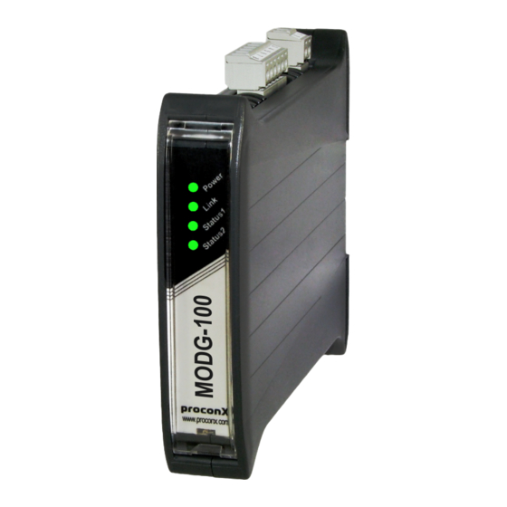
Description Chapter 2. Description The power and RS-485/RS-422 terminals are placed on the top side of the unit. The RS-232 and Ethernet connectors are placed on the bottom side of the unit as shown in the following illustration: TOP VIEW BOTTOM VIEW FRONT VIEW Figure 2.1: Location of connectors ... - Page 10 The following table outlines the indicator condition and the corresponding status after the power-on self test has been completed: Function Condition Indication No power applied to the device. Power Power Green Power supply OK No Ethernet link Link Ethernet link Green Ethernet link OK The device has an unrecoverable fault;...
-
Page 11: Installation
Regulatory notes 1. The MODG-100 is suitable for use in non-hazardous locations only. 2. The MODG-100 is not authorized for use in life support devices or systems. 3. Wiring and installation must be in accordance with applicable electrical codes in accordance with the authority having jurisdiction. -
Page 12: Din Rail Mounting And Removal
DIN rail mounting and removal The MODG-100 gateway is designed to be mounted on a 35 mm DIN rail according to DIN/EN 50022. The enclosure features a 35 mm profile at the back which snaps into the DIN rail. No tools are required for mounting. Please observe the rules outlined in the section called “Mounting rules”. -
Page 13: Powering The Modg-100
Wiring the RS-485/422 interface The RS-485/422 port is used for integrating the MODG-100 into a two-wire or four- wire Modbus over Serial Line network. The use of either the RS-485 or RS-422 interface must be configured using the web interface (See the section called “Configuring Modbus network”). -
Page 14: Wiring The Rs-232 Interface
The RS-232 port can alternativly be used for serial communication to a Modbus Slave device instead of RS-485. The use of the RS-232 interface must be configured using the web interface (See the section called “Configuring Modbus network”). The MODG-100 is a Modbus Master device on this interface. -
Page 15: Connecting Ethernet
Installation • The shield must not be connected to the GND pin. To connect the MODG-100 to a PC (Personal Computer) or any other device with data terminal equipment (DTE) pinout you need a null-modem or cross-over cable. Connecting Ethernet... - Page 16 This page intentionally left blank UMMODG100-2201...
-
Page 17: Ethernet & Ip Configuration
“Temporarily changing the IP settings on your PC”). In order to connect to the MODG-100 via TCP/IP, your PC must be on same IP subnet as the gateway. In most situations this means that the first three numbers of the IP address have to be identical. -
Page 18: Ip Setup Using A Terminal Program Like Hyperterminal
IP setup using a terminal program like HyperTerminal 1. Connect a null modem RS-232 cable between your PC and the MODG-100's Serial Port 1. 2. In Windows XP, click Start, point to All Programs, point to Accessories, point to Communications, and then click HyperTerminal. -
Page 19: Temporarily Changing The Ip Settings On Your Pc
This method involves manually assigning an IP address to your PC in the same subnet as the gateway. The default subnet of the gateway is 169.254.0.0/16. 1. Connect the MODG-100 to your Ethernet network. 2. On a Windows PC, open the Control Panel and double-click on Network Connections. - Page 20 8. Click Configuration… and then Ethernet & IP in the menu on the left side of the page. 9. Enter the IP address, subnet mask, and gateway address assigned to your MODG-100, then click Save. 10.Restore your computer’s original settings.
-
Page 21: Web Browser Based Management
Once you made sure that your PC is configured to be on the same subnet as the MODG-100, start your web browser. In the address box, type the IP address of your device (169.254.0.10 is the default), and then press Enter. (See Chapter 4, Ethernet &... -
Page 22: Monitoring And Diagnostic
In order to connect to the MODG-100 via TCP/IP, your PC must be on same IP subnet as the gateway. In most situations this means that the first three numbers of the IP address have to be identical. Monitoring and diagnostic The MODG-100 offers several web pages which allow monitoring of the status of the different communication networks and the device performance. -
Page 23: Modbus Connection Status
This page is automatically updated every 5 seconds. Figure 5.3: Modbus status page This page shows accumulated readings since the MODG-100 was last activated or reset. If power to the MODG-100 is lost, all cumulative values are reset to zero. The following statistics are maintained: TCP status Status of the Modbus/TCP connection as per TCP finite state machine (refer to RFC 793). - Page 24 Replies A counter that is incremented each time a response message is processed. This value includes exception responses. Broadcasts Number of broadcast messages processed. Value represents the standard Modbus Return Slave No Response Count diagnostic counter. Exceptions Number of exception responses processed. Also includes exception errors detected in broadcast messages even no reply is transmitted in that case.
-
Page 25: Finding The Firmware Version And Serial Number
Bootloader Version The version of the Ethernet bootloader. This is relevant for firmware upgrades. Hardware Type Type of hardware the MODG-100 is based on. The Type is relevant to identify the device for regulatory compliance. Serial Number The serial number of the MODG-100. The serial number is specific to your device. -
Page 26: Configuring Ethernet And Ip
Select Enabled to have the IP address assigned via DHCP. When enabling this option it is important to have a reliable DHCP server available in the network at all times. The MODG-100 will not communicate without an IP address. A missing IP address is indicated with a distinct LED diagnostic code. -
Page 27: Configuring Modbus Network
Web browser based management The new settings are confirmed with the following page: Figure 5.6: IP settings changed to static IP confirmation Please write down the new IP address so you are able to communicate with the device in the future! Figure 5.7: IP settings changed to DHCP confirmation Configuring Modbus network The Modbus parameters for the serial line can be configured to match the serial line configuration of the other Modbus network nodes. - Page 28 The timing for the silence detection can be relaxed with this setting by adding small increments. This enables the MODG-100 to communicate with Modbus devices which may not be fully compliant to the Modbus specification in that respect.
-
Page 29: Remote Restarting The Device
Web browser based management Once you click Save the new settings are stored and applied instantly. A confirmation message is shown. It is of great importance to ensure that there is not two devices with the same Modbus address. In such a case, an abnormal behavior of the whole serial bus can occur, the master being then in the impossibility to communicate with all present slaves on the bus. -
Page 30: Backup And Restoring Of Configuration Settings
Backup and restoring of configuration settings The MODG-100 allows configuration settings to be uploaded onto a PC. This is a beneficial for archiving purposes but also allows easy deployment of similar devices by the means of loading settings from a previously stored reference device. -
Page 31: Password Protection
Web browser based management The successful restoration of configuration settings is confirmed with the following message: In case of an error message, the settings may have only been partially restored and it is important to review all the settings for correctness. Password protection Access to the configuration pages can be protected with a password. -
Page 32: Firmware Upgrade
To log on to password protected configuration pages, click on a configuration menu entry. The web browser will open a password dialog similar to the one shown below: Figure 5.13: Authentication dialog To remove password protection, log on, uncheck the Enable Password checkbox and click Save to confirm. -
Page 33: Decommissioning
1. Ensure that the system power and external supplies have been turned off. 2. Disconnect power supply plug. 3. Disconnect all I/O cables. 4. Remove the MODG-100 from the DIN rail following the procedure described in the section called “DIN rail mounting and removal”. Disposal This product must be disposed of at a specialized electronic waste recycling facility. - Page 34 This page intentionally left blank UMMODG100-2201...
-
Page 35: A Specifications
Specifications Appendix A. S pecifications Product name MODG-100 Interfaces Ethernet Serial ports 1, software configurable as either 1 x RS-232 or 1 x RS-485 or 1 x RS-422 User interface LED indicators Power (green), Ethernet link (green), 2 status (bi-color red/green) Monitoring &... -
Page 36: Dimensions
Fast transients EN 61000-4-4 Conducted RF EN 61000-4-6 Enclosure Material Self-extinguishing PC/ABS blend (UL 94-V0) Mounting 35 mm DIN rail (EN 60715) Classification / Type rating IP 20 / NEMA Type 1 Cooling Convection Environmental Operating temperature 0 to 60 °C / 32 to 140 °F Storage temperature -25 to 85 °C / -13 to 185 °F Humidity rating... -
Page 37: Glossary
Glossary Glossary EIA-422 ANSI/TIA/EIA-422 standard serial transmission of data between two devices, also known as RS-422 and V.11. Remote terminal unit. Also used EIA-485 designate a protocol variant of Modbus. ANSI/TIA/EIA-485 standard serial transmission of data between multiple Modbus devices, also known as RS-485. Fieldbus protocol used in the process automation industry. - Page 38 RS-232 Human-Machine Interface See EIA-232. IEEE RS-422 Institute Electrical Electronics See EIA-422. Engineers RS-485 See EIA-485. Internet Protocol SCADA Supervisory Control and Data Acquisition Ingress Protection Rating according IEC Subnet mask 60529. Standard for various grades of A numeric address used in conjunction with electrical enclosures.
-
Page 39: Index
Index Index enclosure DIN rail clip, 3 front cover, 3 mounting, 6 red hook, 6 About, 19 removal, 6 APIPA, 11 Ethernet, 9, 20 settings, 20 Exceptions, 18 Backup/Restore, 24 Baud rate, 22 Bootloader Version, 19 faults, 16 Broadcasts, 18 features, 2 Brown out reset, 16 Firmware Version, 19... - Page 40 parameters TCP Port, 22 Modbus, 22 TCP status, 17 Parity, 22 temperature Password, 25 operating, 7 Physical Layer, 22 terminal program, 12 pinout termination Ethernet, 9 RS-422, 8 power, 7 RS-485, 8 RS-232, 8 Total Cx, 17 RS-422, 7 Total Rx, 18 RS-485, 7 twisted pairs, 8 power, 7...
- Page 41 Notes Notes UMMODG100-2201...
- Page 42 This page intentionally left blank UMMODG100-2201...
Need help?
Do you have a question about the MODG-100 and is the answer not in the manual?
Questions and answers