Table of Contents
Advertisement
Quick Links
www.ti.com
User's Guide
LMX1204EVM User's Guide
The LMX1204EVM is designed to evaluate the performance of LMX1204. This board consists of an LMX1204
device and an integrated USB2ANY programmer.
The LMX1204 is an ultra-low additive-jitter RF buffer, divider, and multiplier, with integrated SYSREF generation
capability. The device can buffer RF frequencies up to 12.8 GHz, multiply RF outputs up to 6.4 GHz, and
divide outputs by up to 8 GHz. A separate auxiliary clock divider can be used for FPGAs or other logic ICs.
Each RF output (and the logic clock) is paired with a complementary SYSREF output with picosecond-precision
delay-tuning capability, and can be operated as a generator (with synchronization capability across multiple
devices) or as a repeater. The device runs from a single 2.5-V supply, and is programmed by a digital SPI
interface from a 1.8-V, 2.5-V, or 3.3-V bus controller.
SNAU266 – JULY 2021
Submit Document Feedback
ABSTRACT
Copyright © 2021 Texas Instruments Incorporated
LMX1204EVM User's Guide
1
Advertisement
Table of Contents

Subscribe to Our Youtube Channel
Related Manuals for Texas Instruments LMX1204EVM


Summary of Contents for Texas Instruments LMX1204EVM
- Page 1 LMX1204EVM User's Guide ABSTRACT The LMX1204EVM is designed to evaluate the performance of LMX1204. This board consists of an LMX1204 device and an integrated USB2ANY programmer. The LMX1204 is an ultra-low additive-jitter RF buffer, divider, and multiplier, with integrated SYSREF generation capability.
-
Page 2: Table Of Contents
Schematic....................................14 5 PCB Layout and Layer Stack-Up............................16 5.1 PCB Layer Stack-Up................................ 5.2 PCB Layout..................................6 Bill of Materials..................................A Troubleshooting................................... B USB2ANY Firmware Upgrade..............................25 LMX1204EVM User's Guide SNAU266 – JULY 2021 Submit Document Feedback Copyright © 2021 Texas Instruments Incorporated... -
Page 3: First-Time Setup
DC levels (1.25 V ± 0.2 V, differential, into 100-Ω DC load) for triggering SYSREF, SYNCing the dividers, and determining SYSREF windowing values • A phase noise analysis system capable of measuring at up to 12.8 GHz SNAU266 – JULY 2021 LMX1204EVM User's Guide Submit Document Feedback Copyright © 2021 Texas Instruments Incorporated... -
Page 4: Evm Connections
If a suitable input source is available, connect the SYSREF input SMAs to a differential output source such as an arbitrary function generator. The EVM connections for the SYSREF input are DC-coupled and provide LMX1204EVM User's Guide SNAU266 – JULY 2021 Submit Document Feedback Copyright © 2021 Texas Instruments Incorporated... -
Page 5: Output Connections
Connect any of the CLKOUT SMA connectors to a signal analyzer. All CLKOUT connections are AC-coupled at the LMX1204EVM and can be connected directly to RF instruments with 0VDC requirements; an additional DC block is not required. The unused CLKOUT SMA connector must be terminated with a 50-Ω load, or a differential connection may be used if a balun with a suitable frequency range is available. - Page 6 LED several times in rapid succession; the LED will return to solid green once completed. After confirming the USB2ANY connection, close the interface window. LMX1204EVM User's Guide SNAU266 – JULY 2021 Submit Document Feedback Copyright © 2021 Texas Instruments Incorporated...
- Page 7 EVM Connections 4. Ensure that the main window now shows the USB2ANY connection over SPI. SNAU266 – JULY 2021 LMX1204EVM User's Guide Submit Document Feedback Copyright © 2021 Texas Instruments Incorporated...
-
Page 8: Feature Evaluation
After the profile is loaded and any changes required have been made, the signal analyzer should see an 800-MHz signal at around +6-dBm single-ended, or +9-dBm differential. LMX1204EVM User's Guide SNAU266 – JULY 2021 Submit Document Feedback Copyright © 2021 Texas Instruments Incorporated... - Page 9 RESET field, and finally the registers should be reloaded using the USB Communications → Write All Registers menu option, or by pressing the accelerator keys CTRL + L. SNAU266 – JULY 2021 LMX1204EVM User's Guide Submit Document Feedback Copyright © 2021 Texas Instruments Incorporated...
- Page 10 Feature Evaluation www.ti.com Figure 3-3. 3200-MHz Multiplier x4 Mode Signal Analyzer Plot LMX1204EVM User's Guide SNAU266 – JULY 2021 Submit Document Feedback Copyright © 2021 Texas Instruments Incorporated...
-
Page 11: Sysref Generation
LOW→HIGH transition must be seen on SYSREFREQ pins to trigger the pulser. For repeater mode, the output will follow the input state. SNAU266 – JULY 2021 LMX1204EVM User's Guide Submit Document Feedback Copyright © 2021 Texas Instruments Incorporated... - Page 12 SYSREF generator still matches to the falling edge of the clock input even for multiplier and divider modes. Figure 3-6. 3200-MHz Multiplier Mode With CLKOUT, LOGICLK, and SYSREF LMX1204EVM User's Guide SNAU266 – JULY 2021 Submit Document Feedback Copyright © 2021 Texas Instruments Incorporated...
-
Page 13: Sysref Delay Generators
GUI will calculate the correct step values to achieve the requested delay as closely as possible. Alternately, the register-based delay fields can be stepped through or programmed to achieve the same result. Figure 3-7. SYSREF Delay, in 5-Code Steps SNAU266 – JULY 2021 LMX1204EVM User's Guide Submit Document Feedback Copyright © 2021 Texas Instruments Incorporated... -
Page 14: Schematic
Schematic www.ti.com 4 Schematic Figure 4-1. Schematic - LMX1204 LMX1204EVM User's Guide SNAU266 – JULY 2021 Submit Document Feedback Copyright © 2021 Texas Instruments Incorporated... - Page 15 Schematic Figure 4-2. Schematic - USB2ANY SNAU266 – JULY 2021 LMX1204EVM User's Guide Submit Document Feedback Copyright © 2021 Texas Instruments Incorporated...
-
Page 16: Pcb Layout And Layer Stack-Up
RO4350B (Er = 3.66) RF GND layer FR4 (Er = 4.2) Signal GND layer FR4 (Er = 4.2) Bottom layer Figure 5-1. PCB Layer Stack-Up LMX1204EVM User's Guide SNAU266 – JULY 2021 Submit Document Feedback Copyright © 2021 Texas Instruments Incorporated... -
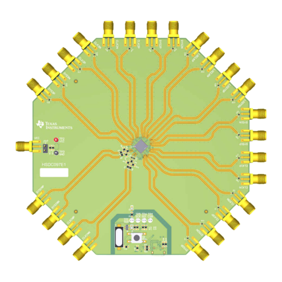
Page 17: Pcb Layout
PCB Layout and Layer Stack-Up 5.2 PCB Layout Figure 5-2. PCB Layer Plot - Top Layer SNAU266 – JULY 2021 LMX1204EVM User's Guide Submit Document Feedback Copyright © 2021 Texas Instruments Incorporated... - Page 18 PCB Layout and Layer Stack-Up www.ti.com Figure 5-3. PCB Layer Plot - Layer 2 (RF GND) LMX1204EVM User's Guide SNAU266 – JULY 2021 Submit Document Feedback Copyright © 2021 Texas Instruments Incorporated...
- Page 19 PCB Layout and Layer Stack-Up Figure 5-4. PCB Layer Plot - Layer 3 (Signal GND) SNAU266 – JULY 2021 LMX1204EVM User's Guide Submit Document Feedback Copyright © 2021 Texas Instruments Incorporated...
- Page 20 PCB Layout and Layer Stack-Up www.ti.com Figure 5-5. PCB Layer Plot - Bottom Layer LMX1204EVM User's Guide SNAU266 – JULY 2021 Submit Document Feedback Copyright © 2021 Texas Instruments Incorporated...
-
Page 21: Bill Of Materials
RES, 1.5 k, 5%, 0.1 W, AEC-Q200 Grade CRCW06031K50JN Vishay-Dale 0, 0603 RES, 1.2 M, 5%, 0.1 W, AEC-Q200 CRCW06031M20J Vishay-Dale Grade 0, 0603 SNAU266 – JULY 2021 LMX1204EVM User's Guide Submit Document Feedback Copyright © 2021 Texas Instruments Incorporated... - Page 22 Texas Instruments 4-Channel ESD Protection Array TPD4E004DRYR Texas Instruments 150mA Linear Regulator, 3.3V LP5900SDX-3.3/ Texas Instruments NOPB Crystal, 24.000 MHz, 20pF, SMD ECS--240-20-5PX- ECS Inc. LMX1204EVM User's Guide SNAU266 – JULY 2021 Submit Document Feedback Copyright © 2021 Texas Instruments Incorporated...
-
Page 23: A Troubleshooting
• The POR current of the LMX1204EVM is between 400 mA and 500 mA with the CLKIN source disabled, and 550 mA with the CLKIN source enabled and oscillating. •... - Page 24 1.1-V source may not be able to sink current from the 1.5-V supply through the internal 100-Ω impedance. An arbitrary function generator is recommended if possible. LMX1204EVM User's Guide SNAU266 – JULY 2021 Submit Document Feedback Copyright © 2021 Texas Instruments Incorporated...
-
Page 25: B Usb2Any Firmware Upgrade
Disconnect the USB cable from the EVM. Figure B-2. Firmware Loader 3. While pressing the BSL button (shown below), connect the USB2ANY cable. Figure B-3. BSL Button Location SNAU266 – JULY 2021 LMX1204EVM User's Guide Submit Document Feedback Copyright © 2021 Texas Instruments Incorporated... - Page 26 Figure B-4. Update Firmware 5. Click Upgrade Firmware to start the firmware upgrade. Click Close after the upgrade is complete. Figure B-5. Firmware Update Complete LMX1204EVM User's Guide SNAU266 – JULY 2021 Submit Document Feedback Copyright © 2021 Texas Instruments Incorporated...
- Page 27 6. Go to USB communications → Interface in the TICS Pro software to check the USB connection. Make sure the USB Connected button is green. Figure B-6. USB Communications SNAU266 – JULY 2021 LMX1204EVM User's Guide Submit Document Feedback Copyright © 2021 Texas Instruments Incorporated...
- Page 28 STANDARD TERMS FOR EVALUATION MODULES Delivery: TI delivers TI evaluation boards, kits, or modules, including any accompanying demonstration software, components, and/or documentation which may be provided together or separately (collectively, an “EVM” or “EVMs”) to the User (“User”) in accordance with the terms set forth herein.
- Page 29 www.ti.com Regulatory Notices: 3.1 United States 3.1.1 Notice applicable to EVMs not FCC-Approved: FCC NOTICE: This kit is designed to allow product developers to evaluate electronic components, circuitry, or software associated with the kit to determine whether to incorporate such items in a finished product and software developers to write software applications for use with the end product.
- Page 30 www.ti.com Concernant les EVMs avec antennes détachables Conformément à la réglementation d'Industrie Canada, le présent émetteur radio peut fonctionner avec une antenne d'un type et d'un gain maximal (ou inférieur) approuvé pour l'émetteur par Industrie Canada. Dans le but de réduire les risques de brouillage radioélectrique à...
- Page 31 www.ti.com EVM Use Restrictions and Warnings: 4.1 EVMS ARE NOT FOR USE IN FUNCTIONAL SAFETY AND/OR SAFETY CRITICAL EVALUATIONS, INCLUDING BUT NOT LIMITED TO EVALUATIONS OF LIFE SUPPORT APPLICATIONS. 4.2 User must read and apply the user guide and other available documentation provided by TI regarding the EVM prior to handling or using the EVM, including without limitation any warning or restriction notices.
- Page 32 Notwithstanding the foregoing, any judgment may be enforced in any United States or foreign court, and TI may seek injunctive relief in any United States or foreign court. Mailing Address: Texas Instruments, Post Office Box 655303, Dallas, Texas 75265 Copyright © 2019, Texas Instruments Incorporated...
- Page 33 TI products. TI’s provision of these resources does not expand or otherwise alter TI’s applicable warranties or warranty disclaimers for TI products.IMPORTANT NOTICE Mailing Address: Texas Instruments, Post Office Box 655303, Dallas, Texas 75265 Copyright © 2021, Texas Instruments Incorporated...
Need help?
Do you have a question about the LMX1204EVM and is the answer not in the manual?
Questions and answers