Table of Contents
Advertisement
Quick Links
Advertisement
Table of Contents

Subscribe to Our Youtube Channel
Related Manuals for Faber FMG3326F


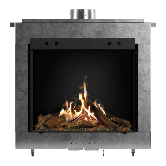
Summary of Contents for Faber FMG3326F
-
Page 2: Table Of Contents
Technical Dimensions FMG3326F/FMG3326F-LP ........ - Page 3 Heat Releases and Air Intakes ................48 Heat Releases .
-
Page 4: Safety Information
SAFETY INFORMATION WARNING • This appliance is hot when operated and can cause • severe burns if contacted. extended period of time. • Any changes or alterations to this appliance or its • Check with your local hearth specialty dealer for safety controls can be dangerous and is prohibited. - Page 5 SAFETY INFORMATION WARNING be kept closed while the appliance is operating to when building a mantel or shelves above the appliance. Elevated temperatures on the wall or in the air above the from entering the home. Temperatures of the exhaust escaping through these openings can also cause the surrounding combustible materials to overheat and •...
- Page 6 Faber requires installation be performed of a match or candle. 8. If improper venting Is observed during any of Faber installer. Installations that do not follow this instruction will not be covered corrected in accordance with National Fuel Gas by warranty or serviced.
-
Page 7: Fireplace Information
This manual should be used for following Faber Matrix models: FMG3326F FMG3326F-LP FMG4326F FMG4326F-LP FMG3726L FMG3726L-LP FMG4726L FMG4726L-LP FMG3726R FMG3726R-LP FMG4726R FMG4726R-LP FMG4126B FMG4126B-LP FMG5126B FMG5126B-LP and operation. • All warnings and instructions apply to all models. -
Page 8: Fireplace Information
Installation Information IMPORTANT Unit Information Model Number Serial Number Owner Information Name Address Technician Information Name Company Technician NPI # Notes... -
Page 9: Maintenance Log
Maintenance Log Service Date Notes FaberFires.com... -
Page 10: Label
Label Outer bottom trim and screen must be removed to access by a chain and located in a dedicated slot under the grate in the location shown above. -
Page 11: Technical Dimensions Fmg3326F/Fmg3326F-Lp
Technical Dimensions FMG3326F/FMG3326F-LP - Front-facing Built-in Gas Fireplace TOP VIEW LEFT SIDE RIGHT SIDE FRONT BOTTOM VIEW (FEET LOCATION) FaberFires.com... -
Page 12: Technical Dimensions Fmg3726L/Fmg3726L-Lp
Technical Dimensions FMG3726L/ FMG3726L-LP - Left-facing Built-in Gas Fireplace TOP VIEW LEFT SIDE RIGHT SIDE FRONT BOTTOM VIEW (FEET LOCATION) -
Page 13: Technical Dimensions Fmg3726R/Fmg3726R-Lp
Technical Dimensions FMG3726R/FMG3726R-LP - Right-facing Built-in Gas Fireplace TOP VIEW LEFT SIDE RIGHT SIDE FRONT BOTTOM VIEW (FEET LOCATION) FaberFires.com... -
Page 14: Technical Dimensions Fmg4126B/Fmg4126B-Lp
Technical Dimensions FMG4126B/FMG4126B-LP - Bay Built-in Gas Fireplace TOP VIEW LEFT SIDE RIGHT SIDE FRONT BOTTOM VIEW (FEET LOCATION) -
Page 15: Technical Dimensions Fmg4326F/Fmg4326F-Lp
Technical Dimensions FMG4326F/FMG4326F-LP - Front-facing Built-in Gas Fireplace TOP VIEW LEFT SIDE RIGHT SIDE FRONT BOTTOM VIEW (FEET LOCATION) FaberFires.com... -
Page 16: Technical Dimensions Fmg4726L/Fmg4726L-Lp
Technical Dimensions FMG4726L/FMG4726L-LP - Left-facing Built-in Gas Fireplace TOP VIEW LEFT SIDE RIGHT SIDE FRONT BOTTOM VIEW (FEET LOCATION) -
Page 17: Technical Dimensions Fmg4726R/Fmg4726R-Lp
Technical Dimensions FMG4726R/FMG4726R-LP - Right-facing Built-in Gas Fireplace 4" (10.2 cm) 2" (5.1 cm) 26-1/8" (66.2 cm) 6-5/8" (16.9 cm) TOP VIEW ADJUSTABLE 24-1/2" (62.2 cm) to 26-1/2" (67.3 cm) 48-1/8" (123.1 cm) ADJUSTABLE 24-1/2" (62.2 cm) 22-1/2" (57.1 cm) 55-1/4"... -
Page 18: Technical Dimensions Fmg5126B/Fmg5126B-Lp
Technical Dimensions FMG5126B/FMG5126B-LP - Bay Built-in Gas Fireplace TOP VIEW LEFT SIDE RIGHT SIDE FRONT BOTTOM VIEW (FEET LOCATION) -
Page 19: Gas Fireplace Operation
Remote Control Instructions FaberFires.com... - Page 21 FaberFires.com...
- Page 23 FaberFires.com...
-
Page 24: Receiver And Remote Batteries
Receiver and Remote Batteries Receiver Batteries Remote Control Batteries • • • Low battery indicator: Frequent beeps for 3 seconds • Low battery indicator on handsets with display. when motor turns. • Battery replacement is recommended every • It is recommended to use batteries as a power backup 2 years. -
Page 25: Installation Steps
2. Determine the following: • • Clearance requirements from combustible and non-combustible materials. • Gas supply piping. • Electrical wiring requirements. • clearance instructions in this manual. 5. Attach the brackets of the unit to the wall framing access door if desired. Install receiver batteries. 10. -
Page 26: Installation Preparation
Fireplace Unpacking and Contents Remove the outer protective crate from the pallet. before installation. All components may not be packed exactly as shown. MatriX Firebox Safety Screen Logs DuraVent Adaptor Decorative Glass... -
Page 27: Fireplace Positioning
Fireplace Positioning • • Unit should remain on the pallet during transport inside the site location. • • • Do not attempt to use a pallet jack or any other moving tools if the unit has been FaberFires.com... -
Page 28: Vent Termination
For detailed chimney installation information please use the manufacturer's direct vent installation manual. WARNING DO NOT pack insulation around the vent. Insulation must be kept back from the pipe to prevent overheating. Vent Size Models Vent Size FMG3326F-LP FMG3326F FMG4326F FMG3726L-LP FMG4326F-LP FMG3726L... -
Page 29: Minimum Combustible Clearances From Vent
Minimum Combustible Clearances from Vent • Horizontal Vent Clearances sides and bottom of the vent pipe on all horizontal runs to combustibles is required. • Vertical Vent Clearances combustibles is required except for clearances in appliance enclosures. • the termination. DirectVent Pro and iCC Compatible Vent Terminations Component Description DuraVent Stock Number... -
Page 30: Minimum Clearances To Vent Termination
Minimum Clearances to Vent Termination Minimum Clearance Requirements Canada¹ USA² Clearance to window or door that may be opened Clearance to permanently closed window See note³ See note³ Clearance to outside corner: with AstroCap Termination Cap. Clearance to outside corner: with all other approved Termination Caps. Clearance to inside comer: with AstroCap Termination Cap Clearance to inside corner: with all other approved Termination Caps Clearance to each side of center line extended above meter/regulator assembly... -
Page 31: Unit Installation With Horizontal Termination
Unit Installation with Horizontal Termination 5 x 8 venting (Rigid Vent Systems) Minimum Vent Clearances to Combustibles * Clearances noted must be maintained except when Horizontal Top* Horizontal Side Horizontal Bottom Vertical Vent Recommended Framed Opening Size Vent Size Framing Size lnstall the vent system according to the manufacturer’s instructions included with the components. - Page 32 Unit Installation with Horizontal Termination Never allow the vent to run downward. This could cause high temperatures and may present the codes. ensure that the termination is not recessed into the siding. The four wood screws provided should be replaced with Center of Hole 8.
-
Page 33: Unit Installation With Vertical Termination
Unit Installation with Vertical Termination rigidity for mounting the termination. See manufacturer's table cutout dimensions for appropriate sizing for component used. Diagram 1 used as noted above. Do not pack clearance space with insulation. Consult the relevant section for the maximum vertical rise of the venting system and the maximum 2. - Page 34 Unit Installation with Vertical Termination due to its higher corrosion resistance. Continue Minimum Vent Height Roof Pitch the height of the vent cap meets the minimum Feet Meters 0.61 over 7/12 to 8/12 0.61 vertical height must be increased. over 8/12 to 9/12 0.61 7.
-
Page 35: Minimum Venting Requirements - Natural Gas
Minimum Venting Requirements FMG3326F, FMG3726L, FMG3726R, FMG4126B, (For Models FMG3326F-LP, FMG3726L-LP, FMG3726R-LP, FMG4126B-LP ONLY) Horizontal Run (H) FaberFires.com... - Page 36 FMG4326F, FMG4726L, FMG4726R, FMG5126B, (For Models FMG4326F-LP, FMG4726L-LP, FMG4726R-LP, FMG5126B-LP ONLY) Horizontal Run (H)
- Page 37 (For All Models) vertical rise is considered the minimum practical dimension for and a minimal building structure. vertical rise may be needed constraints or local codes and / or Horizontal Run (H) regulatory requirements. FaberFires.com...
-
Page 39: Chase And Framing Installation And Planning
Non-Combustible Material Non-Combustible Material Metal Studs Wood Studs Non-Combustible Framing Combustible Framing the exterior of the metal framing. This provides heat and exterior of the wood framing. This provides heat protection for both the combustible framing and the recommended on the inside of the chase when a for more details. - Page 40 Single-Sided Installation FMG3326F FMG3326F-LP Wood framing Metal Framing Reference inches inches 1134 ³ 1102 FMG4326F FMG4326F-LP Wood framing Metal Framing Reference inches inches 1385 1353 1117 1117 Two-Sided Installation FMG3726L/FMG3726R FMG3726L-LP/FMG3726R-LP Wood framing Metal Framing Reference inches inches 1223 1191...
- Page 41 Three-Sided Installation FMG4126B FMG4126B-LP Wood framing Metal Framing Reference inches inches 1315 1283 FMG5126B FMG5126B-LP Wood framing Metal Framing Reference inches inches 1569 1537 Dimension breakdowns: FaberFires.com...
- Page 42 Standard Test Method for Behavior of Materials in a Vertical Tube Furnace at 750 °C shall be considered never overhang into the glass opening. WARNING DO NOT apply combustible materials beyond the minimum clearances. Comply with all minimum Examples of non-combustible materials that can be used: •...
-
Page 43: Clearances
• DO NOT pack airspace with insulation or other materials. Failure to keep insulation or other materials away from • breakage of glass. Improper framing or mounting to unit will void product warranty. Please consult Faber directly for additional questions or concerns about framing options. -
Page 44: Chase Clearances
Chase Clearances WARNING FRONT VIEW Clearance to Metal Framing Metal Studs Wood Studs with Metal Header Clearance to sides and back covers - Non-combustible SIDE VIEW Clearance to sides and back - Covered combustible Combustible material can be used behind cement board as it is a total of combustible material. -
Page 45: Additional Clearances
Chase Clearances Chase Ceiling materials are permitted inside the chase. Floor Clearance remove the feet or install the appliance in a manner that would bypass this minimum elevation. WARNING Additional Clearances Ceiling Clearance The minimum ceiling height required for installation of all Ceiling Clearance The minimum clearance required from the top of the glass... -
Page 46: Mantel Clearance
Mantel Clearance The necessary clearance for a mantel made of combustible height. Use the following table and illustration for information on mantel clearance requirements for mantels made of combustible Ref. Height Max. Depth No maximum > 254 mm 254 mm 305 mm 152 mm 152 mm... -
Page 47: Finishing Around Front Of The Fireplace
Finishing Around Front of the Fireplace glass. See “Mantel Clearance” for requirements. FaberFires.com... -
Page 48: Heat Releases And Air Intakes
Heat Releases airspace. When using accessories such as vent grilles, the opening must be made larger to account for the reduced open airspace. The outlet for heat release from the wall enclosure MUST remain open. The outlet must be at the top part of the through the vent to enter the room. -
Page 49: Examples Of Heat Releases And Air Intakes
Examples of Heat Releases and Air Intakes Classic Registers Drop Wall Shadow Line The wall does not reach the ceiling A recess hides the opening at the top and is left open on top. for a heat release and/or at the bottom vent registers. -
Page 50: Television Mounting Information
WARNING Please note that most television manufacturers and manuals will instruct the owner not to install television above or customer’s or contractor responsibility to verify that their TV or artwork can withstand the wall temperatures at the installation site. • Please note that electric wiring used for the television must be insulated for heat when installed inside the chase •... -
Page 51: Flat With Recessed Tv
Flat with Recessed TV Recessed with recessed TV Heat Release Heat Release TV cables can be TV cables can be placed between placed between noncombustible noncombustible board layers board layers 25mm 25mm 25 mm 51 mm 51 mm 203 mm 203 mm 51 mm 51 mm... -
Page 52: Television Install Flush Above Fireplace
Television Installed Flush Above Fireplace Television Install Without Recess Minimum Requirements for Installing a Television • Heat Release • above the glass. TV cables can be placed between • noncombustible board layers Heat Release TV cables can be placed between noncombustible board layers 51 mm... -
Page 53: Gas Installation
General WARNING RISK OF FIRE OR EXPLOSION! • • • Do not change the gas valve setting! • • for gas leaks. during any pressure testing of the gas supply piping system at test pressures equal to or less than 1/2 psig 1. -
Page 54: Gas Valve
Gas Valve Maxitrol GV60 Gas Valve Pressure Regulator or Throttle Main Valve Knob MANUAL Knob Connection Piezo Igniter Tab 2.8×0.8 mm Side Inlet Magnet Unit Inlet Pressure Tap Bottom Outlet Outlet Pressure Tap Accessing the Gas Valve and Electronic Receiver 1. -
Page 55: Installation At High Altitude
Installation at High Altitude Contact your local gas supplier for de-ration requirements for your area. CAN/CSA-8149.1 code - latest edition. Gas Valve Access Door from the middle of Velcro straps and more. FaberFires.com... -
Page 56: Commonwealth Of Massachusetts
Commonwealth of Massachusetts For all side wall horizontally vented gas fueled equipment signage installed in accordance with the provisions of owned or operated by the Commonwealth and where the side wall exhaust vent termination is less than seven 1. The equipment listed in Chapter 10 entitled “Equipment Not Required To Be Vented”... -
Page 57: Electric And Control
Wiring Diagram A/C adaptor LED Modules Pilot Burner Thermocouple Ignitor Second Thermocouple Thermocouple interrupter box Latching Valve Gas Valve Receiver Box Power Source It is recommended to use batteries as a power backup to the A/C adaptor. Battery replacement is recommended at the beginning of each heating season as part of the yearly service check or more often as needed. -
Page 58: Wall Switch - Optional
Wall Switch - Optional If you wish to install the wall switch option, you will need to purchase the GV60 Wall Switch Accessory Kit, as well as the 2nd thermocouple cable (G60-ZCTCR/[...]) from The GV60 Wall Switch Accessory Kit can be purchased separately as an option to available in various lengths. -
Page 59: Final Installation
Media Arrangement • • • • • frame as that may cause breakage when putting back the front glass. • • FMG3326F, FMG3726L, FMG3726R, FMG4126B FMG3326F-LP, FMG3726L-LP, FMG3726R-LP, FMG4126B-LP in circled areas. the burners. FaberFires.com... - Page 60 Media Arrangement ensure the logs do not move. Closeup of proper installation position of the front two burner logs over the burners.
- Page 61 Media Arrangement 4. Position two back side logs as shown above. 5. Position the two front small logs as shown. 6. Position the two front side logs. 7. Position the back center log. Correct Incorrect Correct media placement versus incorrect placement of media around pilot assembly. FaberFires.com...
- Page 62 Media Arrangement FMG4326F, FMG4726L, FMG4726R, FMG5126B FMG4326F-LP, FMG4726L-LP, FMG4726R-LP, FMG5126B-LP Closeup of proper installation position of the front two burner logs over the burners. 3. Position two back side logs as shown above.
- Page 63 Media Arrangement 5. Position the two front small logs as shown. 5. Place the remaining logs as shown above. Correct Incorrect Correct media placement versus incorrect placement of media around pilot assembly. FaberFires.com...
-
Page 64: Sealing The Glass
Sealing the glass Glass Seal Assembly Diagram • TOP VIEW between the glass panels. Place the front or panel into place so that the silicone edge touches the glass edge. Firebox back wall • Front glass • panel 500ºF RTV High Heat Clear Silicone Sealant is •... -
Page 65: Feature Removal
Safety Screen Removal Follow the instructions below for safety screen removal. WARNING The barrier is designed to reduce the risk of burns from the hot viewing glass and is provided with this appliance. It must remain installed for the protection of children and other at-risk individuals. 1. -
Page 66: Glass Removal
Glass Removal SAFETY PRECAUTIONS The ceramic glass is very fragile and should be handled with care. 1. Loosen the coupling nuts on the bottom front 2. Remove coupling nuts from top front glass glass bracket using a small wrench or socket set. bracket using a small wrench or socket set. -
Page 67: Replacement Parts
..... . 9600820100RP ......Tube of Silicone. -
Page 68: Maintenance
WARNING • season. • • supplier. • Any safety screen or guard removed for servicing must be placed back before operating this appliance. • inspect the unit and to replace any part of the control system and any gas valve that has been under water or impacted. -
Page 69: Yearly Service
Yearly Service Glass Maintenance • • • DO NOT USE abrasive cleaners on the glass panels. DO NOT ATTEMPT to clean the glass panels when they are hot. • leave a permanent stain. • Verify no cracks or breakage in the glass. •... -
Page 70: Flame Pattern
Operation Inspection... -
Page 71: Log Replacement
Log Replacement diagrams under Log Installation. which is not covered under warranty. Glass Gasket required. This gasket is supplied with preinstalled self-adhesive tape. There is also gasket installed on the edge of the inner glass to protect against breakage when installing the glass. Glass materials or cleaners. -
Page 72: Glass Replacement
Glass Replacement Contact Faber for replacement glass if required. Install as per instructions provided with replacement. • • General Vent Maintenance Conduct an inspection of the venting system twice a year. Recommended areas to inspect as follows: 1. Check the Venting System for corrosion in areas that are exposed to the elements. These will appear as rust spots... -
Page 73: Troubleshooting Guide
Unit does not power on using the remote control Remote must learn new code Press and hold the receiver’s reset button until you hear 2 release the reset button and within the subsequent 20 handset until you hear an additional long acoustic signal Remote control is not synced •... - Page 74 Check spark gap; Check for spark in location along cable. No spark at pilot burner. Check spark on the receiver by disconnecting the spark cable from the receiver. Inappropriate inlet pressure Air seal issue around pilot. Inspect and correct as needed. stem-lighter.
-
Page 75: Warranty
Limited Lifetime Warranty Faber extends this Limited Lifetime Warranty to the original purchaser of this appliance provided the product remains in the original place of installation. The items covered by this limited warranty and the period of such coverage is set forth Parts &... - Page 76 Faber may at its own discretion fully discharge all of its purchase price of the product to the original purchaser. of Sale.
- Page 77 Customers should contact the authorized selling dealer to obtain warranty service. In the event the authorized selling Faber by mail at the address listed below. Please include and telephone contact information. A representative will contact you to make arrangements for an inspection and/or warranty service.
Need help?
Do you have a question about the FMG3326F and is the answer not in the manual?
Questions and answers