Table of Contents
Advertisement
Quick Links
Advertisement
Table of Contents

Subscribe to Our Youtube Channel
Related Manuals for Faber Fyn 450 ENG


Summary of Contents for Faber Fyn 450 ENG
- Page 1 Installation manual Fyn 450 ENG 40010929-1840...
- Page 2 1 < < < <...
- Page 3 2 < < < <...
-
Page 4: Safety Instructions
1 Introduction The appliance can only be installed by a competent person in accordance with the Gas Safety. We urgently advise you to read this installation manual properly. This appliance complies with the Gas Appliance Regulation (EU) 2016/426. Harmonized standards applied EN 613 2000/A1 2003. 2 Safety instructions Please note: ... -
Page 5: Installation Requirements
The false chimney breast and its construction may not rest on the appliance. Requirements flue system and outlets You should always make use of the materials prescribed by Faber International Ltd. Only by using these materials can Faber International Ltd. guarantee a proper functioning. -
Page 6: Preparation And Installation Instructions
Terminals The flue outlet can end on an external wall or a roof . Check whether the outlet desired by you complies with local requirements concerning good function and ventilation systems. For a proper functioning the terminal should be at least 0,5m. away from: ... - Page 7 Electric connection If an adapter is used for the power supply, then a wall socket 230VAC – 50Hz must be mounted in the vicinity of the hearth. Preparation of the appliance Remove the packaging of the appliance. Make sure the gas pipes underneath the appliance are not damaged.
-
Page 8: Removing The Glass
Construct the chimney breast against the build-in frame (see fig. 1.1 B). Keep a minimum margin of 3mm between chimney breast and the appliance in connection with the expansion of the appliance. The depth of the recess into the chimney breast has no influence on the removal of the glass. -
Page 9: Checking The Installation
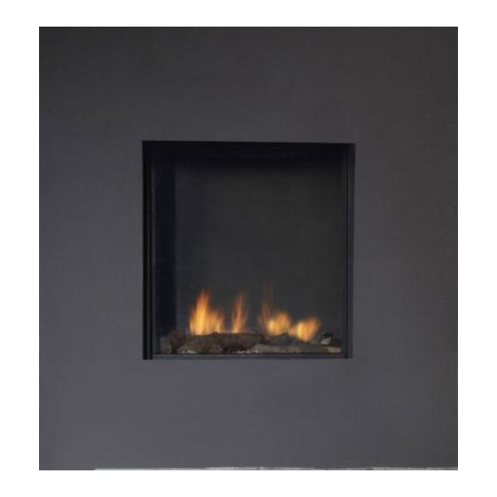
Pebbles Place the pebbles over the burner and the bottom. Spread the pebbles evenly to a double layer. The surface of the pebbles may be very slightly higher than the burner tube (see fig. 3.2 or the instruction card). ... -
Page 10: Instructing The Client
The pressure must agree with the value indicated on the registration plate. In case of deviations, get in touch with the manufacturer. Close the pressure gauge nipples and check these for gas leaks. Checking the flame picture Allow the appliance to burn for at least 20 minutes at full and then check the flame picture for: ... -
Page 11: Annual Maintenance
If necessary the chips/embers. Cleaning the glass Most of the deposits can be removed with a dry cloth. Clean the glass with Faber glass polish. Note: prevent fingerprints on the glass. these will be burned into it once the appliance is used and cannot be removed anymore! Carry-out the check-up according to the instructions in chapter 7 “checking the... -
Page 12: Calculation Of Flue System
11 Calculation of flue system A simple way to calculate whether the exhaust configuration is possible in combination with your fire, use the free “Faber Flue App” and download it from: INTERNET: BlackBerry, Android, PC (Windows Store) APP store: iPhone, iPad and Mac. - Page 13 • Elbows 90° in the horizontal plane: Horizontal bends are bends which are entirely in the horizontal plane (fig. 12.1, 12.2 and 12.3 I, K and Q). • Bends 45° or 30° in the horizontal plane: Horizontal bends are bends which are entirely in the horizontal plane. •...
- Page 14 11.1 Restrictor table Fyn 450 Starting length (STL), Vertical (TVH) and Horizontal (THL) 30,1 30,1 30,1 40,1 50,1 50,1 60,1 60,1 60,1 65,1 65,1 65,1 65,1 65,1 65,1 65,1 65,1 65,1 65,1 65,1 65,1 65,1 65,1 65,1 65,1 65,1 65,1 65,1 65,1 65,1...
- Page 15 12 Examples flue materials Fig. 12.1 Fig. 12.2 Fig. 12.3 14 < < < <...
- Page 16 13 Calculation sheet Starter length (STL) First part on top of the appliance Value Flue length from 0,1m till 0,45m Flue length from 0,5m till 0,90m Flue length from 1m till 1,4m Flue length from 1,5m till 2m Flue length 2m or more Bend 90°...
- Page 17 found value Search in the table at TVH and THL and enter the value that is found. ……………………………… If the detected value is a number, check whether the completed STL is higher or equal to the value in the table. Is the STL value lower as specified in the table then the installation is not possible.
-
Page 18: Technical Data
14 Technical data Technical data Type indication(s) Farum, Fyn, Fyn 450, Concept I-450 Type appliance C11/C31/C91 Diameter outlet/inlet 100/150 Gas connection 3/8" Indirect heating functionality Category II2H3+ Symbol Unit Reference gas/inlet pressure G20-20 G30-30 G31-37 mbar mg/kWh input Emissions in space heating (GVC) Direct heating output Nominal heat output... -
Page 19: Terminal Position
15 Terminal position Please note: These rules apply only for the proper functioning of the unit, for ventilation and environmental protection you need to comply with the applicable rules as defined in the building regulations. Short roof terminal. Only for existing Chimney connection Extension pipe over roof Location... -
Page 20: Troubleshooting Guide
16 Troubleshooting guide 19 < < < <... - Page 21 20 < < < <...
- Page 22 21 < < < <...
-
Page 23: Dimensional Drawings
17 Dimensional drawings 17.1 Fyn 450 22 < < < <... - Page 24 17.2 Ventilation grid 23 < < < <...
- Page 25 17.3 Remote access door 24 < < < <...
- Page 26 25 < < < <...
- Page 27 26 < < < <...
Need help?
Do you have a question about the Fyn 450 ENG and is the answer not in the manual?
Questions and answers