Advertisement
Quick Links
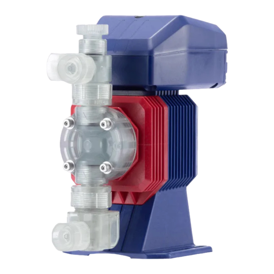
Iwaki
Electromagnetic Metering Pump
EHN-YN
Instruction manual
Thank you for choosing our product.
Please read through this instruction manual before use.
This instruction manual describes important precautions and instruc-
tions for the product. Always keep it on hand for quick reference.
©2010 IWAKI CO., LTD.
Advertisement

Related Manuals for IWAKI PUMPS EHN-YN


Summary of Contents for IWAKI PUMPS EHN-YN
- Page 1 Iwaki Electromagnetic Metering Pump EHN-YN Instruction manual Thank you for choosing our product. Please read through this instruction manual before use. This instruction manual describes important precautions and instruc- tions for the product. Always keep it on hand for quick reference.
- Page 2 Open the package and check that the product conforms to your order. If any problem or inconsistency is found, immediately contact your distributor. a. Check if the delivery is correct. Check the nameplate to see if the information such as model codes, discharge capacity, discharge pressure and power voltage are as ordered.
- Page 3 Contents Safety instructions ..............6 ................................ 7 ................................. 8 ............................ 10 Overview ...................12 ..............................12 ........................... 13 ..............................17 ............................ 22 Installation ................24 ............................24 ..............................25 ................................29...
- Page 4 Operation ................. 33 ............................33 ..........................40 ..............................42 Maintenance ................54 ............................54 ..............................56 ..........................57...
- Page 5 .............................66 ......................71...
- Page 6 Safety instructions Read through this section before use. This section describes important information for you to prevent personal injury or property damage. WARNING CAUTION Requirement Wear Grounding Caution Electrical Prohibited Do not rework protection shock or alter...
- Page 7 WARNINGS Electrical shock Requirement Prohibited Do not remodel Wear protectors Prohibited Prohibited...
- Page 8 CAUTIONS Requirement Prohibited Caution Prohibited Caution Prohibited Requirement...
- Page 9 Prohibited Grounding Electrical shock Requirement Prohibited Requirement Caution Requirement...
- Page 10 Caution Caution Requirement Requirement Caution...
- Page 11 Caution Caution Caution Requirement Caution...
- Page 12 Overview Pump characteristics, features and part names are described in this sec- tion. Pump structure & Operating principle The EHN series is a diaphragm metering pump which consists of a pump head, drive unit and control unit. A diaphragm is directly driven by electromagnetic force.
- Page 13 Features Manual mode Run/stop the pump by the start/stop key. A stroke rate (MAN speed) can be changed in the range of 1-360spm by the up and the down keys at any time during operation or stop. See page 42 for detail.
- Page 14 EXT mode 360spm 20mA Pulse signal input Pump operation 1 2 3 4 5 1 2 3 4 5 Pulse signal input Pump operation 1 2 3 4 5 1 2 3 4 5 1 2 3 4 5 1 2 3...
- Page 15 Pulse signal input 1 2 3 4 5 1 2 3 4 5 1 2 3 4 5 Pump operation STOP signal input Pump operation Stop STOP signal input Pump operation Stop Stop...
- Page 16 1 2 3 4 5 1 2 3 Pump operation Full speed operation Pulse signal input Normal operation Pre-Alarm time Return time Nromal operation Alarm time...
- Page 17 Pump...
- Page 18 Operation panel STOP OVER WAIT ON LED...
- Page 22 Each code represents the following information. Pump EHN - B 11 VC 1 YN - - FCM...
- Page 23 Control unit EHNC - B YN -...
- Page 24 Installation This section describes the installation of the pump, piping and wiring. Read through this section before work. Select an installation location and mount the pump.
- Page 25 Connect tubes to the pump and install a check valve. Tube connection...
- Page 27 Check valve mounting Install an optional check valve to the EHN-YN (or a back pressure valve to the FC type) for the prevention of a In the following cases be sure to install the check valve.
- Page 28 R1/2 R3/8...
- Page 29 Wiring for power voltage, earthing and external signals. Power voltage/Earthing POWER POWER TIME TIME...
- Page 30 Signal wire connection Check that power voltage is turned off. The pump is still charged right after turning off power. Wait for one minute before wiring.
- Page 33 Operation This section describes pump operation and programming. Run the pump after pipework and wiring are completed. before starting operation. Points to be checked Before operation, check if... °...
- Page 34 Degassing The gas needs to be expelled from the pump and tubing by degassing. Normal performance can not be ob- tained with gas in the pump. Conduct degassing in the following cases.
- Page 36 36 VC...
- Page 37 Flow rate adjustment Fixed stroke rate Fixed stroke rate Stroke rate is fixed at 100% Stroke rate is fixed at 100% Stroke rate is fixed at 75% Stroke rate is fixed at 75% Stroke rate is fixed at 50% Stroke rate is fixed at 50% Stroke length adjustment Stroke length adjustment...
- Page 38 Fixed stroke length Stroke rate adjustment...
- Page 39 Fixed stroke rate Stroke length adjustment Before a long period of stoppage (One month or more) Clean wet ends and the inside of piping. Before unplugging the pump When the pump does not transfer liquid at resuming operation.
- Page 40 Operation at each mode is individually set and controlled by keypad operation. Select a prop- er mode to make optimal operation.
- Page 41 STOP ON/OFF selection Buffer ON/OFF selection Buffer ON (Divisor) Buffer OFF (Multiplier) EXT mode selection Digital control (Divisor) Digital control (Multiplier) Power ON Buffer OFF (Divisor) Buffer ON (Multiplier) Wait state Analog control Digital/Analog selection WAIT Digital control Analog control Manual operation WAIT Stroke rate setting...
- Page 42 Read this section before operation. Manual operation Run or stop the pump by keypad operation. EXT operation The pump operation is controlled by the external signal.
- Page 45 Buffer ON/OFF selection Buffer OFF (Divisor) Buffer ON (Divisor) Buffer ON (Multiplier) Buffer OFF (Multiplier) Divisor setting screen Multiplier setting screen Enter a multiplier.
- Page 47 Buffer ON/OFF selection Buffer OFF (Divisor) Buffer ON (Divisor) Buffer ON (Multiplier) Buffer OFF (Multiplier) Divisor setting screen Enter a divisor. Multiplier setting screen...
- Page 48 STOP function The start/stop of the pump operation can be controlled by the external stop signal.
- Page 49 Keypad lock Keypad lock can be active for the prevention of erroneous key operation. Priming function This key operation runs the pump at the maximum stroke rate in operation.
- Page 50 Auto restoration (FCM type)
- Page 53 Error codes...
- Page 54 Maintenance This section describes troubleshooting, maintenance, wear part replace- First check the following points. If the following measures do not help remove problems, con- tact your nearest distributor.
- Page 56 Perform daily and periodic inspection to keep pump performance and safety. Daily inspection Check the following points. Upon sensing abnormality, stop operation immediately and remove problems ac- cording to "Troubleshooting". When wear parts come to the life limit, replace them with new ones. Contact your distributor for detail. Periodic inspection Retighten the pump head mounting bolts evenly to the following torque in diagonal order.
- Page 57 To run the pump for a long period, wear parts need to be replaced periodically. It is recommended that the following parts are always stocked for immediate replacement. Contact your nearest distributor for detail. Wear part list 34 35 17...
- Page 58 Before replacement First release pressure from the pump head and discharge line. Valve set replacement...
- Page 61 Air vent valve set replacement (SH type)
- Page 62 Air vent valve set replacement (NAE type) Flow checker replacement (FCM/XFCM)
- Page 64 Diaphragm replacement...
- Page 66 Pump head, Drive unit & Control unit Do not dismantle the pump beyond the extent shown in the diagram below.
- Page 67 Pump head...
- Page 70 Check valve (VC/VH/PC/PH)
- Page 73 Accessories Options...
- Page 74 Outer dimensions (209) (37) (21) (25) 81.5 7 16 10 (190) (16) (21) 81.5 (27) 7 16 10...
- Page 75 (227) (37) (18) (27) (208) (16) (18) (29)
- Page 76 (184) (12) (21) (25) 81.5 7 16 10 (202) (12) (18) (27)
- Page 77 (208) (16) (18) (29)
- Page 78 (205) (34) Rc1/4 OD φ 4 Rc1/4 (21) (24) 81.5 7 16 10 (226) (37) Rc1/4 OD φ 4 Rc1/4 (18) (26)
- Page 79 (226) (35) Rc1/4 OD φ 4 Rc1/4 (18) (28) (225) (34) Rc1/4 OD φ 4 Rc1/4 (18) (28)
- Page 80 (209) (37) AIR(AUTO) (21) (25) 81.5 7 16 10 (227) (37) AIR(AUTO) (18) (27)
- Page 81 (209) (37) (21) 81.5 (25) (37) 7 16 10 (227) (37) OUT AIR (18) (27) (37)
- Page 84 TEL: +61 2 9899 2411 FAX: +61 2 9899 2421 Germany / IWAKI Europe GmbH Sweden / IWAKI Sverige AB China (Hong Kong) / IWAKI Pumps Co., Ltd. TEL: +49 2154 9254 50 FAX: +49 2154 9254 55 TEL: +46 8 511 72900 FAX: +46 8 511 72922...
Need help?
Do you have a question about the EHN-YN and is the answer not in the manual?
Questions and answers