Advertisement
Quick Links
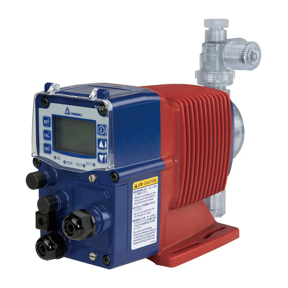
Iwaki
Electromagnetic Metering Pump
EWN-W (For water quality control)
Instruction manual
Thank you for choosing our product.
Please read through this instruction manual before use.
This instruction manual describes important precautions and
instructions for the product. Always keep it on hand for quick
reference.
2008 IWAKI CO., LTD.
Advertisement

Related Manuals for IWAKI PUMPS EWN-W


Summary of Contents for IWAKI PUMPS EWN-W
- Page 1 Iwaki Electromagnetic Metering Pump EWN-W (For water quality control) Instruction manual Thank you for choosing our product. Please read through this instruction manual before use. This instruction manual describes important precautions and instructions for the product. Always keep it on hand for quick reference.
- Page 2 Open the package and check that the product conforms to your order. If any problem or inconsistency is found, immediately contact your distribu- tor. a. Check if the delivery is correct. Check the nameplate to see if the information such as model codes, dis- charge capacity and discharge pressure are as ordered.
- Page 3 Contents Safety instructions ............... 6 ......................7 ......................8 ..................10 Overview ..................12 .....................12 .......................18 ..................21 ......................23 Installation .................. 25 ....................25 ......................26 ................... 30 .......................31...
- Page 4 Operation ..................43 .................... 43 ................48 ......................75...
- Page 5 Maintenance ................79 ..................... 80 ..................... 83 ..................86 ....................... 87 .................. 88 ....................95 EWN- ..............98...
- Page 6 Safety instructions Read through this section before use. This section describes important information for you to prevent personal injury or property damage. WARNING CAUTION Requirement Wear Grounding Caution Electrical Prohibited Do not rework protection shock or alter...
- Page 7 WARNING Electrical shock Requirement Prohibited Do not remodel Wear protectors Prohibited Prohibited WARNING...
- Page 8 CAUTION Requirement Prohibited Caution Prohibited Caution Prohibited Requirement 8 CAUTION...
- Page 9 Prohibited Grounding Electrical shock Requirement Prohibited Requirement Caution Requirement CAUTION...
- Page 10 • Caution – Where • • Caution • Caution Caution • Caution...
- Page 11 • • Caution • Caution • Caution • Requirement • Caution •...
- Page 12 Overview Pump characteristics, features and part names are described in this section. Pump structure & Operating principle The EWN-W is a diaphragm type electromagnetic metering pump which automatically monitors and controls water quality by means of electrodes and sensors.
- Page 13 Features Operational functions SP.2 SP.1...
- Page 14 0:40 0:20...
- Page 18 Pump...
- Page 19 Operational panel...
- Page 20 Error oc-...
- Page 21 The model codes of the pump/drive units and the control unit represent the fol- lowing information. Pump/Drive units EWN - B 11 VC E WPO Code PTFE PTFE GFRPP...
- Page 22 code* ø ø ø ø...
- Page 23 The EWN-W always needs sensors during operation. • • •...
- Page 25 Installation This section describes the installation of the pump, tubing and wiring. Read through this section before work. • • • • Select an installation location and mount the pump. • NOTE...
- Page 26 Connect tubes to the pump and install a check valve. Tube connection...
- Page 28 Check valve mounting Install an optional check valve to the EWN phon and overfeeding. In the following cases be sure to install the check valve. • • •...
- Page 29 NOTE NOTE • •...
- Page 30 pH/ORP electrode Observe the instruction manual of the pH/ORP electrode. Always select "MTC" in AUTO/MAN TC selection. See page 66 for detail. Conductivity sensor...
- Page 31 Wiring for a power voltage and an external signal. • • • • Power voltage/Earthing...
- Page 32 End terminals See the following diagram for detail.
- Page 33 NOTE • • POWER POWER TIME TIME • •...
- Page 34 • • • • Signal wire connection Use the DIN 4- or 5-pin female connector cable. We recommend the use of Binder connector cables (German manufacturer). Contact us for detail. Binder round connector cables 5-pin : 713 series 99-0436-10-05 Input signal 4-pin : 715 series 99-0430-15-04 Stop signal Hirschmann square connector cables...
- Page 35 NOTE • • • • • When using an open collector: • When using a contact:...
- Page 36 • When using an open collector: • When using a contact: • OUT1<Mechanical relay>: Upper limit alarm, Lower limit alarm or Batch alarm • OUT2<PhotoMOS relay>: Upper limit alarm, Lower limit alarm, Batch alarm or Syn- chronous output.
- Page 37 Sensor cable connection • NOTE • • • For the WCT, remove the terminal case and pass the sensor cable into the cable path as below. For the WPO, connect the sensor cable via the BNC connector. Always select "MTC (Manual Temperature Compensation)" in User mode after the connec- tion.
- Page 38 NOTE • • • •...
- Page 39 Multibox (Relay type) The WCT type needs a Multibox (relay type) when making blowdown control. Outer dimensions (148) 4× ø 5...
- Page 40 NOTE 4× ø 5...
- Page 41 100-240VAC • OUT2 Black Blue White Brown OUT2 terminal OUT1 • When using OUT2:...
- Page 42 Earthing Power 100-240VAC supply 50/60Hz Blowdown valve NOTE NOTE...
- Page 43 Operation This section describes pump operation and setting. Run the pump after plumbing and wiring is completed. adjustment before starting operation. Points to be checked Before operation, check if: • EWN-B31 EWN-C31 EWN-C36...
- Page 44 ° Degassing The gas needs to be expelled from the pump and tubing by degassing. Normal performance can not be obtained with gas in the pump. Conduct degassing in the following cases. NOTE • •...
- Page 45 NOTE •...
- Page 46 • • • • •...
- Page 47 Before a long period of stoppage (One month or more) • • • •...
- Page 48 Operation at each mode is individually set and controlled by keypad operation. Select a proper mode to make optimal operation. STEP AUTO or MAN AUTO 1200 0 - 399 0 - 399 AUTO or MAN AUTO AUTO or MAN AUTO...
- Page 49 STEP*1 1000 0 - 99 ON or OFF STOP ON or OFF ON or OFF ON or OFF SENS ON or OFF 0000 - 9999 0000...
- Page 50 Keypad lock Power ON 3sec Auto operation Enter PIN number. Operating state Wait state Liquid temperature 1sec 1sec 1sec 1sec Priming mode Calibration mode User mode...
- Page 51 Perform a calibration Before calibration, program measurement conditions in the user mode. See page 64 for detail. And then enter the calibration mode and calibrate this prod- uct at each measuring object. NOTE • Calibration for pH measurement (WPO type): •...
- Page 52 NOTE • • NOTE...
- Page 56 • Sensitivity check by ORP • Man calibration NOTE...
- Page 58 • Cell constant • Reading...
- Page 60 User mode Press and hold the SET key for one second in the wait state (the bottom line displays "WAIT".). The pump enters the User mode. Push the start/stop key when returning to the wait start.
- Page 61 AUTO/MAN selection Menu selection AUTO operation MAN operation keys...
- Page 62 • WPO/WEC types Control parameter programming Menu selection Process value at SP.1 keys Enter a to enter value. process value. SPM at SP.1 Enter spm. Enter process values and spm at Process value at SP.2 SP.1 and SP.2 for Enter a process value. proportional control.
- Page 63 • WCT type Control parameter programming Menu selection Starting point Enter a process keys value to start to enter value. blowdown control. Stop point Enter a process value to stop blowdown control. SPM setting Program a spm that the pump runs at.
- Page 64 Menu selection pH/ORP selection (WPO type) Select pH or ORP. See page 65 for detail. pH buffer selection (WPO type) Select a pH buffer type for the automatic calibration. See page 65 for detail. AUTO/MAN pH calibration selection (WPO type) Select AUTO or MAN pH calibration.
- Page 65 • pH/ORP selection pH mode ORP mode keys to change menus. • pH buffer selection (WPO type) pH4.7.9(JIS) pH2.7.9(JIS) pH4.7.10(US) keys to change menus. • AUTO/MAN pH calibration (WPO type) AUTO keys to change menus.
- Page 66 • Measured value adjustment keys to change values. *Setting range changes with measuring object. WPO PH: -2.00 - 2.00pH WPO ORP: -200 - 200mV WEC/WCT: -100 - 100mS/m • AUTO/MAN TC selection (WPO with pH/WCT types) AUTO keys to change menus. •...
- Page 67 Menu selection STOP function Program ON-OFF operation via the STOP signal. See page 68. Interlock function Program ON-OFF operation via the interlock signal. See page 68. OUT1 Program alarm output. See page 69. Programing menus will be added OUT1 depending on OUT1 setting. setting menu OUT2...
- Page 68 • STOP function keys to change menus. • Interlock function keys to change menus.
- Page 69 • OUT1 and 2 function OUT1 Upper alarm Lower alarm OUT2 Batch alarm Synchronous output (OUT2 only) Not used keys to change menus.
- Page 70 • Upper alarm, lower alarm and batch alarm programming Menu selection OUT1 or 2 Upper limit Hysteresis keys to enter value. Additional menus will appear after Delay time OUT1 or 2. keys to scroll thorough menus.
- Page 71 Menu selection OUT1 or 2 Lower limit Hysteresis keys to enter value. Additional menus will appear after Delay time OUT1 or 2. keys to scroll thorough menus.
- Page 72 Menu selection OUT1 or 2 Interlock STOP keys to select ON/OFF. Additional menus will appear after PreSTOP OUT1 or 2. Sensor failure keys to scroll thorough menus.
- Page 73 Stroke rate keys to chagne units. Measured value keys to scroll thorough menus.
- Page 74 Entry screen Pine number entry Push key to move to next digit. Push key to change values.
- Page 75 Read this section before operation. AUTO operation The pump monitors and controls process solution automatically.
- Page 76 MAN operation Run or stop operation manually. Priming function This key operation runs the pump at the maximum stroke rate in operation.
- Page 77 Keypad lock Keypad lock can be active for the prevention of erroneous key operation. NOTE •...
- Page 79 Maintenance This section describes troubleshooting, electrode/sensor main- cations. • • • NOTE • • •...
- Page 80 First check the following points. If the following measures do not help removing problems, contact us or your nearest distributor. • • • • • • • • • • • • • • • • • • • • •...
- Page 81 - • • • • • • • • • • • • • • • •...
- Page 82 - • • • • • • • • • • • • • • •...
- Page 83 Error codes will be shown when this product is in a faulty condition. See below for the meanings of error codes and countermeasures. Error code ERR2 ERR3 ERR4 ERR5 ERR6 • ERR7 • ERR8 Error code • ERR7 • • •...
- Page 84 Error code • • • • • • • • • • • ERR2 • • • • ERR3 • • • • ERR4 • • • • • • ERR5 • • ERR6 • • • • ERR7 • •...
- Page 85 Error code • • • • • • • • ERR7 • • ERR8 • • ERR9 • • error...
- Page 86 Daily inspection • Cleaning process NOTE...
- Page 87 Perform daily and periodic inspection to keep pump performance and safety. Daily inspection Check the following points. If you notice any abnormal or dangerous condi- tions, suspend operation immediately and inspect/solve problems. When wear parts come to the life limit, replace them with new ones. Contact us or your nearest distributor for detail.
- Page 88 To run the pump for a long period, wear parts need to be replaced periodically. It is recommended that the following parts are always stocked for immediate replacement. Contact us or your nearest distributor for detail. • • • Wear part list...
- Page 89 Before replacement First release pressure from the pump head. NOTE NOTE Valve set replacement • • •...
- Page 91 *VC• •PC• NOTE...
- Page 92 *VC• •PC• Diaphragm replacement • • • NOTE...
- Page 94 NOTE • • • EWN-B09 EWN-B31 EWN-C31 EWN-C36...
- Page 95 Pump head, Drive unit & Control unit The pump in the diagram below is completely dismantled. Do not dismantle the pump beyond the extent shown in this instruction manual.
- Page 96 Pump head...
- Page 98 Information in this section is subject to change without notice. EWN-B11 EWN-B16 EWN-B21 EWN-B31 EWN-C16 EWN-C21 EWN-C31 EWN-C36 VC• EWN-B09 EWN-B11 EWN-B16 EWN-B21 EWN-C16 EWN-C21...
- Page 99 PC• EWN-B11 EWN-C16 0 - 60 C...
- Page 100 AUTO STOP OUT1 OUT2...
- Page 102 Outer dimensions (30) (292) (47) LOCK (23) MODEL (114) WPO(BNC) (98) WEC/WCT C31 VC (30) (295) (48) LOCK (98) (25) MODEL (114) WPO(BNC) WEC/WCT (98)
- Page 103 (30) (294.5) (48) LOCK (24) MODEL (114) WPO(BNC) WEC/WCT (98) (30) (307) (62) LOCK (98) (23) MODEL (114) WPO(BNC) WEC/WCT (98)
- Page 104 EWN SERIES EN ISO12100 EN61000-6-2 EN50581 EN809 EN61000-6-3 IS-51K-520-1...
- Page 108 TEL: +81 3 3254 2935 FAX: +81 3 3252 8892 / IWAKI Europe GmbH Norway / IWAKI Norge AS Australia / IWAKI Pumps Australia Pty Ltd. TEL: +49 2154 9254 0 FAX: +49 2154 9254 48 TEL: +47 23 38 49 00 FAX: +47 23 38 49 01...
Need help?
Do you have a question about the EWN-W and is the answer not in the manual?
Questions and answers