
Related Manuals for IWAKI PUMPS EH-E Series


Summary of Contents for IWAKI PUMPS EH-E Series
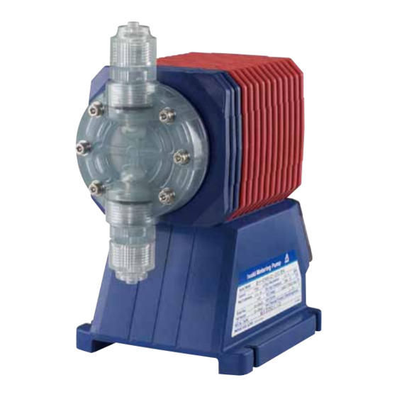
- Page 1 IWAKI Electromagnetic Metering Pump EH-E Type Instruction Manual Read this manual before use of product...
-
Page 2: Table Of Contents
Thank you for choosing an Iwaki's EH-E Series metering pump. This instruction manual deals with the correct installation, operation, maintenance, and trou- bleshooting procedures for the EH-E model metering pump. Please read through it carefully to ensure the optimum performance, safety and service of your pump. -
Page 3: Important Instruction
Important Instruction For the Safe and Correct Handling of the Pump • Read the "Safety Instructions" sections carefully to prevent accidents involving your customers or other person and to avoid damage or loss of other assets. Always follow the instructions and advice found in these sections. •... -
Page 4: Safety Section
Safety Section Warning • Turn off the power supply Working without disconnecting the power supply cause an electrical shock. Before engaging upon any working procedures involving the pump, make sure to turn the Electrical Shock power supply switch off and to stop the pump and other related devices. •... - Page 5 Safety Section Caution • Qualified operators only The pump operator and pump operation supervisor must not allow any operators who have little or no knowledge of the pump to run and operate the pump. Pump Prohibited operators must have a sound knowledge of the pump and its operation. •...
- Page 6 Safety Section Caution • Arrange grounding Do not operate the pump without connecting the grounding wire. Otherwise, an electrical shock may result. Make sure the grounding wire is connected with Grounding grounding terminal. • Install an earth leakage breaker The operation of a pump without using an earth leakage breaker may cause an electrical shock.
-
Page 7: Introduction
1. INTRODUCTION 1. Unpacking ........... 6 2. Operation Principle ......6 3. Specifications ........7 4. Operation Function ......10 5. Controller Display ......12 6. Dimensions ........14 - 5 -... -
Page 8: Unpacking
1. Unpacking After unpacking the goods, check the following points to ascertain that the product is exactly as you ordered. If you find anything wrong, please get in touch with your dealer. (1) Do the model, voltage, etc., shown on the name- plate represent what you ordered? (2) Has the goods been damaged in transit? Are the bolts and nuts loose? -
Page 9: Specifications
3. Specifications • Pump identification EH - E 30 PC - 23U P E 8 - M M h j k a Series name EH Series s Drive component E : 48 W d Diaphragm effective diameter 30 : 30 mm 35 : 35 mm 45 : 45 mm 55 : 55 mm f Material of liquid end Symbol Pump head... - Page 10 h Power code with plug No symbol without plug j Controller E : E type k Connection Applicable hose dia. (ID × OD) Symbol Type φ 8 × φ 13 (mm) VC, V6, PC, VM φ 9 × φ 12 (mm) VC, V6, PC, VM φ...
- Page 11 • Pump specifications Output Output per Maximum Stroke Stroke Model capacity Stroke Pressure frequency length % (ml/min) (ml/stroke) (MPa) (spm) (mm) 0.19 ~ 0.94 35 (SH) 0.29 ~ 1.44 0.7 (0.6) 20 ~ 100 0 ~ 360 (0.3~1.5 mm) 0.42 ~ 2.08 1250 0.69 ~ 3.47 Note 1.
-
Page 12: Operation Function
4. Operation Function • Manual operation Stroke rate can be set from 0 to 360 spm with keys , and pump start and stop can be done with keys START/STOP. Both setting can be done while the pump stops or operates. Operation chart START/STOP key stop... - Page 13 • Digital input (pulse multiply) operation Pump makes strokes from 1 to 999 responding to external pulse signal. Stroke rate is the spm set for man- ual operation. The pulses which came while operation are put in memory up to 255 pulses. (It is possible to make the pulses not to be put in memory.) Digital input (multiplying) example (X 5) Ext.
-
Page 14: Controller Display
5. Controller Display • Controller display and panel START/STOP key Alpha/numeric display Manually starts or Indicates stroke frequency, or external mode or external stops the pump. This key is used in settings. setting external modes. SET point indicator EXT indicator Visible when SET point 1 and Visible when pump is 2 are set at EXT mode and... - Page 15 Display examples Meanings Running at EXT operation mode (Dividing). Display shows running at 5 : 1 dividing. WAIT EXT STOP OVER SET Running at EXT operation mode (Analog input 0 - 20 mA). Display shows running at 120 spm speed responding to input current. WAIT EXT STOP OVER SET In setting mode.
-
Page 16: Dimensions
6. Dimensions (Material symbol: VC/V6/PC/VM/FC) • EH-E30 (242) 16.5 114.3 25.4 • EH-E35 (242) 16.5 114.3 25.4 - 14 -... - Page 17 6. Dimensions (Material symbol: VC/V6/PC/VM/FC) • EH-E45 (242) 114.3 25.4 • EH-E55 (242) 21.5 114.3 25.4 - 15 -...
- Page 18 6. Dimensions (Material symbol: SH) • EH-E30 (249) Rc 1/4 φ Rc 1/4 • EH-E35 (249) Rc 1/4 φ Rc 1/4 114.3 25.4 - 16 -...
- Page 19 6. Dimensions (Material symbol: SH) • EH-E45 Rc 3/8 (254) φ Rc 3/8 • EH-E55 (259) Rc 3/8 φ Rc 3/8 114.3 25.4 - 17 -...
-
Page 20: Installation
2. INSTALLATION 1. Notes on Installation ......19 2. Location ..........21 3. Tubing ..........22 4. Electrical Wiring ........ 25 - 18 -... -
Page 21: Notes On Installation
1. Notes on Installation Operators and maintenance service staff must read the instruction manual thoroughly before using the prod- ucts. Do not operate the pump system unless all of the contents in the manual are completely understood. Caution • Turn off the power supply Working without disconnecting the power supply may cause an electrical shock. - Page 22 3. Install the pump at the place convenient for the maintenance/inspection works in the future. Securely fix the pump so that the pump can not vibrate horizontally. 4. Use the tube corresponding to the pump suction and discharge port sizes. Securely connect the tube so that liquid can not leak or air can not be sucked in.
-
Page 23: Location
2. Location Choose a location for the pump which is clean, dry, close to an electrical outlet, and allows convenient access to stroke length control, frequency control, and tubing connections. Avoid areas where ambient temperature exceeds 40 °C or falls below 0 °C, or where the pump or tubing would be exposed to direct sunlight. Flooded suction (mounting the pump below the level of liquid in the supply tank) is strongly recommended, especially when pumping liquids that readily generate gas bubbles. -
Page 24: Tubing
3. Tubing 1. Tubing for types VC, V6, PC, VM, FC · Mount securely the tube with fitting nut, hose stopper and fitting spacer referring to the illus- tration on left. Hose · Pay attention not to tighten fitting nut exces- Fitting nut sively. - Page 25 4. Mounting check valve In case the pump is installed as mentioned below, make sure to install the check valve to avoid over-feeding. 1) In case the suction side liquid level is higher than that of discharge side. (Fig. A) 2) In case the suction side pressure is higher than the discharge side one.
- Page 26 6. Precautions when mounting check valve 1) Install the check valve at the end of discharge tubing. It should be separated the pump by 1 meter or more. CA type check valve 2) CA type check valve can be connected to either tube or threaded pipe of R1/2 and R3/8.
-
Page 27: Electrical Wiring
4. Electrical Wiring 1. Precautions on wiring Caution Only qualified operator/service staff should be in charge of the related electrical arrangement and control of the power source. Failure to observe this instruction may result in injury to person or damage to assets. 1) The control unit can be detached but do not detach it when unnecessary. - Page 28 2. Wiring Power cord and external signal cord are connected according to the procedure as bellow. Caution · Never do the wiring when pump is operating. Otherwise you will get an electric shock or the pump will be failed due to the short-circuit. ·...
- Page 29 • Wiring for stop function Stop function means the method to provisionally r t y u i stop the pump operation by external potential free contact signal or open collector signal. For the wiring, connect the wires to y and i of the connector.
-
Page 30: Operation
3. OPERATION 1. Precaution for Operation ......29 1-1. Bleeding ..........29 1-2. Adjustment of Discharge Capacity ..31 2. Operation ..........33 2-1. Overview Operating Scheme .... 33 2-2. Setting and Operation of Controller .. 35 - 28 -... -
Page 31: Precaution For Operation
1. Preparation for Operation Caution • Do not operate the pump with discharge-side valve completely closed. Operating the pump with discharge-side valve fully closed may lead to liquid leakage or pipe rupture. • Do not run pump dry. Dry operation of the pump over a long time (longer than 30 minutes) causes the pump to overheat and the pump unit (pump head, valve guide etc.) to become deformed or the pump head attachment to become loose, which may result in liquid leakage trouble. - Page 32 Bleeding for types VC, V6, PC and FC Fitting nut 1) Return the discharge side hose to the tank and start the pump. Remove the check valve if it is Remove mounted. check valve 2) Run the pump for 10 minutes for bleeding. 3) When the air is removed and pump head is com- pletely filled with liquid, return the discharge Return...
-
Page 33: Adjustment Of Discharge Capacity
1-2. Adjustment of Discharge Capacity Adjustment of the discharge capacity can be done by adjusting the stroke length and by adjusting the stroke rate but basically it is done by adjusting the stroke rate. Stroke length adjustment is an auxiliary way when the stroke rate adjustment is not enough. - Page 34 3. Adjustment of stroke length (1) Power on the pump to start and adjust the discharge capacity by turning the stroke length adjustment knob. (2) Figure below shows the relation between the stroke length and discharge capacity. Stroke length can be adjusted from 0 to 100 % but actually set the length between 50 and 100 %. Fixed stroke rate Stroke length Caution...
-
Page 35: Operation
2. Operation 2-1. Overview Operating Scheme - 33 -... - Page 36 Notes to Overview Operating Scheme 1) ------> means automatic movement. After the program Ver is displayed, it automatically moves to the sta- tus at which the power was off last time. (When the pump is powered for the first time, it comes to WAIT mode.) 2) For the pump start by manual operation, push START/STOP key at WAIT mode.
-
Page 37: Setting And Operation Of Controller
2-2. Setting and Operation of Controller Manual operation (1) Power ON START/STOP When the power is on, a green lamp lights up and the word- ing “V3.0E” appears, then the stroke rate for manual opera- tion is displayed and comes to WAIT mode. (In case the WAIT EXT STOP OVER SET pump is powered on for the first time.) If it does not come to... - Page 38 Automatic operation 1. Analog signal operation (1) Power ON START/STOP When the power is on, a green lamp lights up and the wording “V3.0E” appears, then the stroke rate for manual operation is displayed and comes to WAIT mode. (In case WAIT EXT STOP OVER SET the pump is powered on for the first time.) If it does not...
- Page 39 (6) Push EXT key to confirm the value at SET point 1 and START/STOP move to the setting of stroke rate for the current value of SET point 1. The words PO is displayed and SET and 1 light. WAIT EXT STOP OVER EH-E (7) Setting of stroke rate for the current value at SET point 1...
- Page 40 (12) Push START/STOP key to confirm the set value and START/STOP move to WAIT mode. WAIT EXT STOP OVER SET EH-E (13) Push EXT key to start the pump. START/STOP Pump operates according to the set current value. WAIT disappears and ON lamp blinks. Display shows the stroke rate at which the pump oper- WAIT STOP OVER...
- Page 41 (2) Move to EXT operation mode. START/STOP Push key and EXT key simultaneously. The word dIG is displayed and SET lights. (If the word ANA is displayed, push key to change to WAIT EXT STOP OVER dIG. Every time you push key, the words ANA and dIG switch over.) When the pump is shipped from the EH-E...
- Page 42 (7) Switching of operation mode START/STOP Push EXT key and key simultaneously and / 1 (Dividing operation mode) is displayed and SET lights. (If X 1 is displayed, go to next (8). WAIT EXT STOP OVER EH-E If you push EXT key, the display changes to X 1 START/STOP (Multiplying operation).
- Page 43 (11) Push EXT key to operate the pump. START/STOP Pump starts to operate, WAIT goes out and ON lamp blinks when a pulse comes. The pump automatically stops after it operated for the WAIT STOP OVER stroke number which is set at above item (8). During the operation, the display shows pre-set stroke number and EH-E EXT lights.
- Page 44 (3) Move to pulse memory (The function to memorize the START/STOP pulses (max. 255 pulses) which come while the pump does -- OF the multiply operation.) Push EXT key and / -- OF or / -- ON is displayed and SET EXT STOP OVER WAIT lights.
- Page 45 (7) Switching of operation mode START/STOP Push EXT key and key simultaneously, and / 1 (Pulse dividing operation mode) is displayed and SET lights. WAIT EXT STOP OVER EH-E If X1 (multiplying mode) is displayed, push EXT key to START/STOP change to / 1.
- Page 46 (11) Push EXT key to start the pump. WAIT disappears and START/STOP ON lamp blinks. Dividing ratio is displayed and EXT lights. Stop the pump, push START/STOP key to come to WAIT WAIT STOP OVER mode. When the pump is started next time, push EXT key. EH-E Alarm indication If pulses which exceeds upper stroke rate come, OVER...
-
Page 47: Maintenance
4. Maintenance 1. Maintenance ........46 2. Diaphragm Replacement ....46 3. Valve Replacement ......46 4. Tubing ..........46 5. Consumable parts ......46 6. Names of Part and Structure .... 47 7. Troubleshooting ......... 49 - 45 -... -
Page 48: Maintenance
1. Maintenance Caution Before working on the pump, disconnect the power cord, depressurize the discharge tubing and drain or flush any residual liquid from the pump head and valves. 2. Diaphragm Replacement Disconnect AC power to the pump and disconnect the suction tubing and discharge tubing. Remove the four head bolts with a 5 mm hex wrench. -
Page 49: Names Of Part And Structure
6. Names of Part and Structure (1) Pump Head Unit (Material symbol: VC/V6/PC/P6/VM/FC) EH-E55 EH-E45 EH-E30/35 20 21 20 21 Parts name for types VC/V6/PC/VM/FC Q'ty Parts name for types VC/V6/PC/VM/FC Q'ty Pump head O-ring (Gasket for type FC) Fitting Diaphragm spacer (Note 4) Fitting nut... - Page 50 (2) Pump Head Unit (Material symbol: SH) E30/E35 E45/E55 Parts name for type SH Q'ty Parts name for type SH Q'ty Pump head Spring washer 4 (6) Suction fitting Gasket Discharge fitting Diaphragm Fitting Retainer Fitting gasket Back up retainer (Note 1) Air vent gasket Valve guide...
-
Page 51: Troubleshooting
7. Troubleshooting Caution Before working on the pump, disconnect the power cord, depressurize the discharge tubing and drain or flush any residual liquid from the pump head and valves. Problem Possible Cause Corrective Action Pump does not start Faulty wiring Correct wiring Improper voltage Connect to proper voltage source... - Page 52 TEL : (1)508 429 1440 FAX : 508 429 1386 Germany : IWAKI EUROPE GmbH TEL : (49)2154 9254 0 FAX : 2154 1028 Australia : IWAKI Pumps Australia Pty. Ltd. TEL : (61)2 9899 2411 FAX : 2 9899 2421 Italy : IWAKI Italia S.R.L.
Need help?
Do you have a question about the EH-E Series and is the answer not in the manual?
Questions and answers