Table of Contents
Advertisement
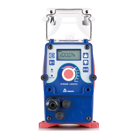
Iwaki
Electromagnetic Metering Pump
EWN-R (Standard)
Instruction manual
Thank you for choosing our product.
Please read through this instruction manual before use.
This instruction manual describes important precautions and
instructions for the product. Always keep it on hand for quick
reference.
2008 IWAKI CO., LTD.
Advertisement
Table of Contents

Related Manuals for IWAKI PUMPS EWN-R


Summary of Contents for IWAKI PUMPS EWN-R
- Page 1 Iwaki Electromagnetic Metering Pump EWN-R (Standard) Instruction manual Thank you for choosing our product. Please read through this instruction manual before use. This instruction manual describes important precautions and instructions for the product. Always keep it on hand for quick reference.
-
Page 2: Order Confirmation
Order confirmation After unpacking, check the following points. Contact us or your nearest dealer if the delivery is imperfect. a. Check if the delivery is as per order. Check the nameplate to see if the dis- charge capacity, discharge pressure and voltage are as per order. -
Page 3: Table Of Contents
Contents Order confirmation ..................... 2 Safety instructions ............... 6 Warning ......................7 Caution ......................8 Precautions for use ..................10 Outline ..................12 Introduction ..................... 12 Pump structure & Operating principle ............12 Features ....................... 13 Operational function ..................13 Part names ....................... - Page 4 Operation ......................36 Before operation .................... 36 Points to be checked .................. 36 Retightening of pump head fixing bolts ............36 Degassing ....................37 Flow rate adjustment .................. 40 Stroke rate adjustment ................41 Stroke length adjustment ............... 43 Before a long period of stoppage (One month or more) ......44 Operation programming ................
- Page 5 Maintenance ................76 Troubleshooting ..................... 77 Inspection ....................... 79 Daily inspection ...................79 Periodic inspection ..................79 Wear parts replacement ................80 Wear parts list ..................... 80 Before replacement ..................81 Valve set replacement .................81 Discharge valve set dismantlement/assembly ........81 Suction valve set dismantlemt/assembly ..........83 Diaphragm replacement ................
-
Page 6: Safety Instructions
Safety instructions Read through this section before use. This section describes important information for you to prevent personal injury or property damage. ■ Pictorial indication In this instruction manual, the estimated risk of degree caused by incorrect use is ranked with the following pictorial indications. First, fully understand informa- tion on the pictorial indications. -
Page 7: Warning
WARNING Turn off power before work Risk of electrical shock. Be sure to turn off power to stop the pump and related devices before work. Electrical shock Stop the operation On sensing any abnormality or dangerous sign, suspend the opera- tion immediately and inspect/solve problems. -
Page 8: Caution
CAUTION A qualified operator only The pump must be handled or operated by a qualified person with a full understanding of the pump. Any person who is not familiar with Requirement this product should not take part in the operation or management. Use a specified power only Do not apply any power other than the one specified on the nameplate. - Page 9 Do not use the pump in a water place The pump is not totally waterproof. The use of the pump in water or high humidity could lead to electrical shock or short circuit. Prohibition Earthing Risk of electrical shock. Always earth the pump. Earthing Install an earth leakage breaker An electrical failure of the pump may adversely affect related de-...
-
Page 10: Precautions For Use
Precautions for use • Electrical work shall be performed by a qualified opera- tor. Otherwise, personal or property damage accident may result. Caution • Do not install the pump in the following places where... –Under a flammable atmosphere or in a dusty/humid place. –Under direct sunlight or wind &... - Page 11 • Be careful not to drop the pump onto the floor. A strong impact may reduce pump performance. Do not use a pump which has once damaged. Otherwise an electrical leak or shock may result. • The pump is a light water-/dust-proof structure of IP65, but is not totally waterproof.
-
Page 12: Outline
Outline The information such as characteristics, features and part names are described in this section. Introduction Pump structure & Operating principle The EWN series is a diaphragm metering pump which consists of a pump head, drive unit and control unit. A diaphragm is directly driven by electromag- netic force. -
Page 13: Features
Features ● Multi voltage All the EWN-R series is multivoltage type (100-240VAC) and can be selected without concern for local power voltage. ● High resolution Digitally-controlled stroke rate range is 0.1-100%. The stroke length shifts for a fine flow adjustment. - Page 14 Multiplier programming (See page 51) 1-9999 shots can be programmed to one pulse signal. *In the EXT operation, the pump runs at the manual operation stroke rate. *The pump runs in 1:1 operation when the multiplier is programmed to 1. Example) When the multiplier is programmed to 5, the pump makes five shots per signal.
- Page 15 ANA. R (analogue rigid) programming The pump increases/decreases a flow rate in proportion to 0-20mA. Four (4- 20, 20-4, 0-20, 20-0) programs are provided. In "4-20" or "20-4" program a disconnection sensor works to stop the pump as a current value falls below 4mA ("DISCN" blinks on the screen). Check wiring as necessary.
- Page 16 ● STOP function (See 60 page) The start/stop of the pump can be controlled by the external signal. When "NOR. OP" is selected... The pump stops while receiving the external signal via the STOP terminal. *The pump resumes operation when the STOP signal is released. STOP signal input Pump operation Stop...
- Page 17 ● AUX function (See 37 page) The pump runs at the maximum stroke rate while receiving the external sig- nal via the AUX terminal. Use this function for degassing. Pulse signal input Pump operation 1 2 3 4 5 1 2 3 ●...
-
Page 18: Part Names
Part names Pump Adjusting screw Used for opening the air vent port. Control unit Used for the start/stop of the Air vent port pump and stroke rate adjust- Always connect a tube. ment/programming.. Be sure to return the tube end to the supply tank or another container. -
Page 19: Operational Panel
Operational panel Display An operational status, current mode and programmed value are shown here. Start/stop key Used for starting/stopping UP key the pump operation. Used for increasing numeric val- ues or selecting a programming mode. EXT key Used for entering the EXT mode. -
Page 20: Basic Displays & Pump States
■ Basic displays & Pump states STOP LED ON LED lights ON LED lights ON LED blinks lights redly orange greenly greenly Manual wait The pump state. Display is running in ― shows stroke ― manual mode. rate in %. Display shows stroke rate in % EXT(Multiply) - Page 21 STOP LED ON LED lights ON LED lights ON LED blinks lights redly orange greenly greenly EXT(Multiply) programming mode. The MULT pump is set ― ― ― to make the displayed # of shots per signal. EXT(Divide) programming mode. The pump is set ―...
-
Page 22: Identification Codes
Identification codes The model codes of the pump/drive units and the control unit represent the fol- lowing information. Pump/Drive units EWN - B 11 VC f g h a. Series name EWN: Multivoltage electromagnetic metering pump b. Drive unit code (Average power consumption) B: 20W C: 24W c. - Page 23 e. Tube connection bore code Hose size (ID×OD) Wet end materials Pump model ø4×ø6 VC/VH/PC/PH/TC/VC-C/VH-C EWN-09/-11/-16 & -21 ø9×ø12 VC/VH/PC/PH EWN-31 & -36 ø10×ø12 EWN-31 & -36 ø6×ø12 VC-C/VH-C EWN-09/-11/-16 & -21 EWN-11/-16/-21/-31 Rc 1/4 FC/SH/SH-H code* & -36 IN: ø15×ø22 PC/P6-V EWN-31 OUT: ø9×ø12...
-
Page 24: Installation
Installation This section describes the installation of the pump, tubing and wiring. Read through this section before work. Observe the following points when installing the pump. • Be sure to turn off power to stop the pump and related devices before work. •... -
Page 25: Pipework
Pipework Connect tubes to the pump and install a check valve. Tube end (Side view) Before operation • Cut the tube ends flat. Necessary tools • Adjustable wrench or spanner Tube connection a. Pass a tube into the fitting nut and Tube hose stopper. - Page 26 Connect an air bleed tube into the Air vent port air vent port. Place the tube end in the supply tank or another container. Tube Direction of the air vent port. The air vent port can rotate 90 de- Air vent port grees.
-
Page 27: Check Valve Mounting
Check valve mounting Install an optional check valve to the EWN (or a back pressure valve to the FC type) for the prevention of a back flow, siphon and overfeeding. In the following cases be sure to install the check valve. •... - Page 28 Mount the check valve at the discharge tube end. * The CAN/CBN check valve and the BVC back pressure valve have R1/2 and R3/8 thread connections as well as tube connection. Cut off and adjust the connection length to fit the check valve into tubing. CAN check valve BVC back pressure valve R1/2...
-
Page 29: Wiring
Wiring Wiring for the power source and external signal. Observe the following points during wiring work. • Electrical work shall be performed by a qualified operator. Always ob- serve applicable codes or regulations. • Observe the rated voltage range. Otherwise the electrical circuit on the control unit may break. - Page 30 NOTE • Do not share a power source with a high power equipment which may generate surge voltage. Otherwise electronic circuit may fail. The noise caused by the inverter also affects the electronic circuit. • Power voltage shall be charged at a sitting via a switch or a relay. Otherwise CPU may malfunction.
-
Page 31: External Input Cable
Precautions for ON-OFF control by the relay The control unit is equipped with CPU. Always start/stop the pump by the STOP signal. Do not start/stop the pump by turning ON/OFF power because it may adversely affect CPU. If there is no choice but to turn ON/OFF power, observe the following points. - Page 32 NOTE • Do not install the EXT/STOP signal wires in parallel with a power cable or combine them in a concentric cable (ex. 5 wires cable). Otherwise noise is generated through the EXT/STOP signal wires due to induction effect and it results in malfunction or failure.
-
Page 33: Connections
■ Connections • Level sensor The EWN have two stage level sensor, the Pre-STOP and STOP alarms. Con- nect the pre-alarm signal to the Pre-STOP and the alarm signal to the STOP. The pre-alarm functions just to notify a low liquid level by flashing the LED orange while the pump is running. - Page 34 • Pulse signal In the EXT (MULT or DIV) mode, the pump runs along with multiplier or divider as receiving the pulse signal. • When using an open collector... Pay attention to polarity. Pulse is plus(+), and COM1 is minus(-). (Maximum 1.8mA at 5V) •...
- Page 35 • OUTPUT signal The pump sends out the OUTPUT signal along with injections or the STOP signal along with the external STOP signal input via a Photo MOS relay. *The maximum applied voltage is 24VAC/DC. 1 : Free 2 : Free 3 : Free 4 : OUT 5 : COM...
-
Page 36: Operation
Operation Run the pump after pipework and wiring is completed. This section describes pump operation and programming. Before operation Check the flow rate, tubing and wiring. And then perform degassing and flow rate adjustment before starting operation. Points to be checked Before operation, check if... -
Page 37: Degassing
■ Use of hexagon wrench instead of a torque wrench Fasten the fixing bolts as tight as can be by the hand with the straight long part of a hexagon wrench (a) and further turn the bolts clockwise 90 degrees with the short part (b). - Page 38 Points to be checked Air bleed tube • An air bleed tube is connected to the pump. Turn on power. The ON LED lights and a display related to the current mode appears on the screen. * The pump enters the wait state in the manual mode when turning on power with a default STOP setting.
- Page 39 Run the pump at the maximum stroke rate. Select a convenient way from the following. • Set the stroke rate to 100% and run the pump manually. STOP STOP • Enter the external signal via the AUX terminals. AUX signal STOP STOP input...
-
Page 40: Flow Rate Adjustment
Flow rate adjustment A flow rate can be adjusted by the stroke rate and stroke length. The stroke rate is indicated in %. 100% stroke rate means the maximum flow rate. Stroke rate adjustment is a main way to adjust a flow rate. Stroke length is the moving distance of the plunger. -
Page 41: Stroke Rate Adjustment
Flow rate, stroke rate and stroke length B type C type Fixed stroke rate Fixed stroke rate Stroke rate is fixed at 100% Stroke rate is fixed at 100% Stroke rate is fixed at 75% Stroke rate is fixed at 75% Stroke rate is fixed at 50% Stroke rate is fixed at 50% Stroke length adjustment... - Page 42 Turn on power and call up manual mode. Enter manual mode to indicate stroke rate on the screen. • Push the start/stop key when "MULT", "DIV", "ANA.R" or "ANA.V" is on the screen. STOP • When "STOP" or "-STOP" appears on the screen, see "STOP function cancellation"...
-
Page 43: Stroke Length Adjustment
■ Stroke length adjustment Stroke length can be adjusted when the moving distance of the plunger is changed by the stroke length adjusting knob. The stroke length adjustment range is 50-100% for the B type, 40-100% for C type. The relation between a flow rate* and stroke length is shown as below. Fixed stroke rate Stroke length adjustment *The flow rate described on the nameplate is at 100%. -
Page 44: Before A Long Period Of Stoppage (One Month Or More)
Before a long period of stoppage (One month or more) Clean the insides of pump head and tubing. • Run the pump with clean water for about thirty minutes to rinse the insides of the pump head and tubing. Before unplugging the pump •... -
Page 45: Operation Programming
Operation programming The pump operation is programmed and controlled by a control unit. The pump is controlled in different ways at each operation mode. Default setting and setting range Parameters Default setting Setting range Step Stroke rate* 100.0% 0.1-100.0% 0.1* Multiply/Divide/Analogue ANA-V, ANA-R, /NNNN, selection... -
Page 46: Programming Flow
Programming flow Power ON Calibration mode Manual mode 3 sec. Stroke rate setting EXT mode Manual operation Save Cancel MULT ANA. V Prime mode 1 sec. ANA.R ANA-V ANA-R Flow rate display programming routine programming routine Keypad lock ANA. V ANA.R LOCK ANA. - Page 47 3 sec. User mode EXT mode programming EXT mode selection MULT See ANA-V programming routine See ANA-R programming routine 2 LOCK Operation programming...
-
Page 48: Manual Operation
Manual operation Turn on power. The LED lights and a display related to the cur- rent mode appears on the screen. * The pump enters the wait state in the manual mode STOP when turning on power with a default setting. The pump calls up the last screen at a shutoff if it was not in a default setting. -
Page 49: Ext Operation
Push the start/stop key. The pump starts to run. • The LED starts to blink at each shot. STOP STOP EXT operation The pump operation is controlled by the external (pulse) signal. ■ EXT mode Set the upper limit spm and enter EXT mode. Note that the pump starts to run in sync with the external signal as entering EXT mode. -
Page 50: Ext Mode Programming
Use the UP or DOWN key to program the upper limit. Push the start/stop key and stop the pump when the pump is running. Then program stroke rate. • A stroke rate increases/decreases as pushing the UP/DOWN keys. • Press and hold either key for three seconds for quick change. Quick change stops at 0.1 or 100%. - Page 51 Multiplier programming Program the number of shots per signal to control the pump. The number of shots can be programmed from 1 to 9999. NOTE Do not enter the external signal during programming. Enter EXT mode. Push the EXT key to move from manual mode to EXT mode. * Push the start/stop key and stop the pump when the pump is running.
- Page 52 Push the EXT key and call up the multiplier programming screen. MULT STOP STOP Disp SET Use the UP or DOWN key to program a multiplier. • A multiplier increases/decreases as pushing the UP/DOWN keys. • Press and hold either key for three seconds for quick change. Quick change stops at 1 or 9999.
- Page 53 Divider programming Program the number of signals per shot to control the pump. The number of signals can be programmed from 1 to 9999. NOTE • If a divider is programmed to 1 to make 1:1 operation and the input interval of the ex- ternal signal is close to a manual operation stroke rate (but not exactly in synchroniza- tion), an irregular operation may occur.
- Page 54 Push the EXT key and call up the multiplier programming screen. STOP STOP Use the UP or DOWN key to program a divider. • A divider increases/decreases as pushing the UP/DOWN keys. • Press and hold either key for more than three seconds for quick change.
- Page 55 ANA-V programming Select "ANA-V" or "ANA-R" in USER mode. See page 66. Enter EXT mode. Push the EXT key to move from manual mode to EXT mode. * Push the start/stop key and stop the pump when the pump is running. Then call up EXT mode.
- Page 56 Push the Disp key and enter a stroke rate at P1. • A stroke rate increases/decreases as pushing the UP/DOWN keys. • Press and hold either key for three seconds for quick change. Quick change stops at 0 or 100%. 0 or 100% skips to 100 or 0% when the key is released and pushed again.
- Page 57 Push the start/stop key to return to EXT mode. The pump starts to run in proportional control according to the ANA-V programming. ANA. V STOP STOP ANA-R programming Select "ANA-V" or "ANA-R" in USER mode. See page 66. Enter EXT mode. Push the EXT key to move from manual mode to EXT mode.
- Page 58 Push the EXT key and select a preset program. ANA.R STOP STOP Scroll through the ANA-R programming routine by the UP and DOWN keys. Push the EXT key to return to the EXT mode selection. ANA.R STOP STOP Push the start/stop key to enter EXT mode. ANA.R STOP STOP...
-
Page 59: User Mode
User mode The following features can be programmed. Get access to User mode via the wait state in the manual mode. • STOP function The pump stops running while receiving the external signal via the STOP terminal. • Pre-STOP function The STOP LED lights orange while the pump receiving the external signal via the Pre-STOP terminal. -
Page 60: Stop/Pre-Stop Function
■ STOP/Pre-STOP function The start/stop of the pump operation can be controlled by the external stop signal. • When "NOR. OP" is selected... The pump stops while receiving the stop signal. • When "NOR. CL" is selected... The pump runs while receiving the stop signal. STOP/Pre-STOP function programming Return to the wait state in the manual mode. - Page 61 Select "STOP" or "P-STP". Scroll through the User mode selection by the UP and DOWN keys. Push the EXT key. STOP STOP Select "NOR. OP" or "NOR. CL". Push the start/stop key to return to manual mode. STOP STOP The screen indicates that the STOP function is active. Operation programming...
-
Page 62: Stop/Pre-Stop Function Cancellation
■ STOP/Pre-STOP function cancellation A stop state can be cancelled if the current selection is changed. Example) NOR.OP→NOR.CL NOR.CL→NOR.OP Call up "-STOP" screen. If the screen shows "STOP" in the manual or EXT mode, push the start/ stop key. STOP Press and hold the EXT key for three seconds to enter User mode. - Page 63 Push the EXT key and change the current selection. If "NOR.OP" is selected change it to "NOR.CL", and vice versa. STOP Push the start/stop key to return to manual mode. STOP STOP The STOP or Pre-STOP function now has been cancelled. Operation programming...
-
Page 64: Output Function
■ OUTPUT function • When "OUT"→"SPM" is selected... The pump sends the OUTPUT signal at each shot while running. • When "OUT"→"STOP" is selected... a. The pump sends the OUTPUT signal while receiving the STOP signal (with the setting of operation stop at STOP signal input). b. - Page 65 Push the EXT key. STOP STOP Select "STOP" or "SPM". Push the start/stop key to return to manual mode. STOP STOP The programming has now been reflected to the pump operation. Operation programming...
-
Page 66: Ana-V/-R Selection
■ ANA-V/-R selection • When "ANA-R" is selected... The preset proportional control programs of "4-20", "20-4", "0-20" and "20-0" are available. • When "ANA-V" is selected... A proportional control pattern can be newly programmed. NOTE A default setting is "ANA-R". Return to the wait state in the manual mode. - Page 67 Push the EXT key. STOP STOP Select "ANA-R" or "ANA-V". Push the start/stop key to return to manual mode. STOP STOP The programming has now been reflected to the pump operation. Operation programming...
-
Page 68: Buffer On/Off Selection
■ Buffer ON/OFF selection • When "bM-ON" is selected... Excessive external signals that are not reflected to the MULT or DIV opera- tion can be stored. • When "bM-OF" is selected... Excessive external signals are not stored. NOTE A default setting is "bM-OF". Return to the wait state in the manual mode. - Page 69 Push the EXT key. STOP STOP Select "bM-ON" or "bM-OF". Push the start/stop key to return to manual mode. STOP STOP The programming has now been reflected to the pump operation. *The pump can run up to 65535 shots by the stored excessive signals. Operation programming...
-
Page 70: Pin Number Entry
■ PIN number entry A PIN is required to release a keypad lock state. NOTE A default setting is "bM-OF". Return to the wait state in the manual mode. Push the start/stop key to return to the manual wait state if the pump is running in manual mode or in EXT mode. - Page 71 Push the EXT key. STOP STOP 2 LOCK Use the UP and DOWN keys to create PIN number. 2 LOCK 2 LOCK Shift to the next digit by pushing the DISP key. *A default PIN number is "00000". Push the start/stop key to return to manual mode. STOP 2 LOCK STOP...
-
Page 72: Keypad Lock
Keypad lock Keypad lock can be active in the following states for the prevention of errone- ous key operation. Manual mode Wait state During operation STOP STOP EXT mode MULT STOP STOP ANA-R ANA- V STOP STOP NOTE • Any key operation is not acceptable when the keypad lock is active. In an emergency, unplug the pump or enter the external signal via the STOP terminal to stop operation. -
Page 73: Keypad Lock Activation
■ Keypad lock activation Press and hold the start/stop key for more than three seconds. STOP STOP LOCK "LOCK" indication appears on the screen. ■ Keypad lock release Push the EXT key once. Enter the PIN number. STOP LOCK STOP LOCK Shift to the next digit by pushing the DISP key. -
Page 74: Calibration Mode
Calibration mode Entering a flow rate per shot, the flow rate can be checked in GPH, L/h or mL/m. Run the pump in an actual operating condition and measure the flow for one minute. Return to the wait state in the manual mode. Push the start/stop key to return to the manual wait state if the pump is running in manual mode or in EXT mode. -
Page 75: Unit Change
Enter the measured flow. Shift to the next digit by pushing the DISP key. *Pushing the EXT key, the programming is cancelled. Push the start stop key to return to the wait state. The programming is stored as "SAVE" indication appears on the screen. The maximum flow can be checked at each unit. -
Page 76: Maintenance
Maintenance This section describes troubleshooting, inspection, wear part replacement, exploded views and specifications. Important • Observe instructions in this manual for maintenance, inspection, disman- tlement and assembly. Do not dismantle the pump beyond the extent of the instructions. • Always wear protective clothing such as an eye protection, chemical resistant gloves, a mask and a work cap during dismantlement, assembly or maintenance work. -
Page 77: Troubleshooting
Troubleshooting First check the following points. If the following measures do not help removing problems, contact us or your nearest dealer. States Possible causes Solutions The pump Power voltage is too low. • Recover the power voltage to a does not normal level. - Page 78 States Possible causes Solutions Liquid leaks. Loose fit of the fitting or the air vent • Retighten them. body. Loose fit of the pump head. • Retighten the pump head. See page 36. O rings or valve gaskets are not •...
-
Page 79: Inspection
Inspection Perform daily inspection and periodic inspection to keep pump performance and safety. Daily inspection Check the following points. Upon sensing abnormal condition, stop the opera- tion immediately and remove problems according to "Troubleshooting". When wear parts come to the life limit, replace them by new ones. Contact us or your nearest dealer for detail. -
Page 80: Wear Parts Replacement
Wear parts replacement For a long operation wear parts need to be replaced periodically. It is recommended that the following parts are always stocked for immediate replacement. Contact us or your nearest dealer for detail. Precautions • When dismantling the pump, pay attention to the residual liquid in the pump. -
Page 81: Before Replacement
* Wear part duration varies with the pressure, temperature and characteristics of the liquid. * The estimated life is calculated based on the continuous operation with ambient clean water. Before replacement First release the pressure from the pump. Stop the pump operation. Rotate the adjusting screw two revolutions anticlockwise to open the air vent port. - Page 82 Loosen the fitting nut and remove a dis- Fitting nut charge tube and an air bleed tube. Air bleed tube Discharge tube Turn the lock nut anticlockwise by Air vent body A Lock nut an adjustable wrench and remove the air vent body A. Remove the air vent body B by the 21mm box wrench.
-
Page 83: Suction Valve Set Dismantlemt/Assembly
Air vent body B Place a new valve set into the pump head. Screw the air vent body B into the pump head Lock nut through the lock nut. * Be careful not to misarrange the valve set or misplace upside down. -
Page 84: Diaphragm Replacement
Pull out the valve set by a pair of tweezers. Screw the fitting into the pump head with the valve set in it and turn it anticlockwise about 90 degrees by an adjustable wrench or a Valve set spanner. * Be careful not to misarrange the valve set or mis- place upside down. - Page 85 Run the pump and set the stroke length to 0%. Then stop the pump. Loosen the fitting nuts and remove a suction tube, a discharge tube and an air bleed tube. Fitting nut Air bleed tube Discharge tube Suction tube Remove the pump head by a hexagon wrench.
- Page 86 NOTE • Fit the retainer to the diaphragm with its round edge Mating parts Bracket to the diaphragm. • Check that the bracket spacer is in place. Refit the bracket spacer into the bracket, combining mating parts as necessary. • The B/C-31 & -36 types do not have a bracket spacer.
-
Page 87: Exploded View
Exploded view Pump head, Drive unit & Control unit The pump in the diagram below is completely dismantled. Do not dismantle the pump beyond the extent shown in this instruction manual. Air vent FC type Control unit Diaphragm spacer Case Valve gasket set*... -
Page 88: Pump Head
Pump head ■ EWN-[B09•B11•B16•B21•C16•C21][VC•VH•PC•PH•TC] Part names # of parts Pump head Fitting Fitting nut Air vent body B Lock nut Diaphragm Retainer 10 Air vent body A 11 Valve guide 12 Valve seat 13 Valve 14 Valve gasket 17 O ring 18 Diaphragm spacer Hex. -
Page 89: Ewn-[B31•C31•C36][Vc•Vh•Pc•Ph•Tc]
■ EWN-[B31•C31•C36][VC•VH•PC•PH•TC] Part names # of parts Pump head Fitting Fitting nut Diaphragm Retainer 11 Valve guide 12 Valve seat 13 Valve 14 Valve gasket 17 O ring 18 Diaphragm spacer 19 Hex. socket head bolt [PW•SW] 29 Hose stopper 30 Hose adaptor 31 O ring * The number of diaphragm spacers varies... -
Page 90: Ewn- Fc
■ EWN- FC Part names # of parts Pump head Fitting Fitting nut Diaphragm Retainer 11 Valve guide 12 Valve seat 13 Valve 14 Valve gasket 17 Gasket 18 Diaphragm spacer 19 Hex. socket head bolt [PW•SW] 29 Hose stopper 30 Hose adaptor 31 O ring * The number of diaphragm spacers varies... -
Page 91: Ewn-C31Pc/P6-V
■ EWN-C31PC/P6-V Part names # of parts Pump head Fitting Fitting nut Diaphragm Retainer 11 Valve guide 12 Valve seat 13 Valve 14 Valve gasket 17 O ring 19 Hex. socket head bolt [PW•SW] 28 Hose stopper 29 Fitting spacer 30 O ring 51 Inlet 52 Valve spring... -
Page 92: Ewn- Sh & Sh-H
■ EWN- SH & SH-H Part names # of parts 1 Pump head 3 Fitting 7 Diaphragm 9 Retainer 11 Valve guide 12 Valve seat 13 Valve 14 Valve gasket B 18 Diaphragm spacer 19 Hex. socket head bolt [PW•SW] 28 Valve gasket A 37 Adjusting screw 38 Seal nut... -
Page 93: Specification/Outer Dimension
Specification/Outer dimension Specification Specifications and apparent condition are subject to change without notice. ■ Pump unit VC•VH•PC•PH Discharge Stroke length Stroke rate Power con- Current Model code Flow rate Weight pressure sumption value mℓ/min (mm) (spm) 2.28 EWN-B11 (38) EWN-B16 (65) 50-100 (0.5-1.0) - Page 94 VC•VH (High compression type) Discharge Stroke length Stroke rate Power con- Current Model code Flow rate Weight pressure sumption value mℓ/min (mm) (spm) 0.72 EWN-B09 (12) 1.38 EWN-B11 (23) 50-100 2.40 (0.625-1.25) EWN-B16 (40) 0.1-100 3.78 (1-180) EWN-B21 (63) 3.24 EWN-C16 (54) 40-100...
-
Page 95: Power Cable
■ Power cable Conduction 0.75 [mm ] Triplex cable(L/N/PE) Standard H03VV-F section area Terminal Length 2000 [mm] European plug treatment ■ Pump colour Blue Munsell colour system 7.5PB 3/8 Munsell colour system 5R 3/10 Specification/Outer dimension... -
Page 96: Outer Dimensions
Outer dimensions ■ EWN-[B11•B16•B21] [VC•VH•PC•PH] (265) (47) (68) (23) ■ EWN-B31[VC•VH•PC•PH] (267) (48) LOCK (68) (125) (25) 96 Specification/Outer dimension... - Page 97 ■ EWN-[C16•C21] [VC•VH•PC•PH] (265) (47) LOCK (68) (23) ■ EWN-C31 [VC•VH•PC•PH] (267) (48) LOCK (68) (125) (25) Specification/Outer dimension...
- Page 98 ■ EWN-C36 [VC•VH•PC•PH] (267) (48) LOCK (68) (24) ■ EWN-[B11•B16•B21]FC (231) (13) (68) (23) 98 Specification/Outer dimension...
- Page 99 ■ EWN-B31FC (236) (16) (68) (25) ■ EWN-[C16•C21]FC (231) (13) (68) (23) Specification/Outer dimension...
- Page 100 ■ EWN-C31FC (236) (16) (68) (25) ■ EWN-C36FC (235) (16) (68) (24) Specification/Outer dimension...
- Page 101 ■ EWN-[B11•B16•B21]TC (265) (47) LOCK (68) (23) ■ EWN-B31TC (267) (48) LOCK (68) (25) Specification/Outer dimension...
- Page 102 ■ EWN-[C16•C21]TC (265) (47) LOCK (68) (23) ■ EWN-C31TC (267) (48) LOCK (68) (25) Specification/Outer dimension...
- Page 103 ■ EWN-C36TC (268) (49) LOCK (68) (24) ■ EWN-[B11•B16•B21]SH (232) (15) (68) (22) Specification/Outer dimension...
- Page 104 ■ EWN-B31SH (233) (15) (68) (23) ■ EWN-[C16•C21]SH (232) (15) (68) (22) Specification/Outer dimension...
- Page 105 ■ EWN-C31SH (233) (15) (68) (23) ■ EWN-C36SH (233) (15) (68) (23) Specification/Outer dimension...
- Page 106 ■ EWN-[B09•B11•B16•B21] [VC•VH] (High compression type) (265) (47) LOCK (68) (23) ■ EWN-[C16•C21] [VC•VH] (High compression type) (265) (47) LOCK (68) (23) Specification/Outer dimension...
- Page 107 ■ EWN-B11 [PC•PH] (High pressure type) (279) (62) LOCK (68) (23) ■ EWN-C16 [PC•PH] (High pressure type) (279) (62) LOCK (68) (23) Specification/Outer dimension...
- Page 108 ■ EWN-B11SH (High pressure type) ■ EWN-C16SH (High pressure type) (232) (15) (68) (22) Specification/Outer dimension...
- Page 109 ■ EWN-C31 [PC•P6] (High viscosity type) (238) (20) (68) (23) Specification/Outer dimension...
- Page 112 TEL : (47)66 81 16 60 FAX : 66 81 16 61 China IWAKI Pumps (Shanghai) Co., Ltd. TEL : (86)21 6272 7502 FAX : 21 6272 6929 Philippines IWAKI Chemical Pumps Philippines, Inc. TEL : (63)2 888 0245 FAX : 2 843 3096 China IWAKI Pumps (Guandong) Co., Ltd.
Need help?
Do you have a question about the EWN-R and is the answer not in the manual?
Questions and answers