Advertisement
Quick Links
Iwaki
Electromagnetic Metering Pump
EWN-WCL (For FRC control)
Instruction manual
Thank you for choosing our product.
Please read through this instruction manual before use.
This instruction manual describes important precautions and
instructions for the product. Always keep it on hand for quick
reference.
2009 IWAKI CO., LTD.
Advertisement

Subscribe to Our Youtube Channel
Related Manuals for IWAKI PUMPS EWN-WCL


Summary of Contents for IWAKI PUMPS EWN-WCL
- Page 1 Iwaki Electromagnetic Metering Pump EWN-WCL (For FRC control) Instruction manual Thank you for choosing our product. Please read through this instruction manual before use. This instruction manual describes important precautions and instructions for the product. Always keep it on hand for quick reference.
- Page 2 After unpacking, check the following points. Contact us or your nearest distributor if the delivery is imperfect. a. Check if the delivery is as per order. Check the nameplate to see if the information such as model codes, discharge capacity and discharge pressure are as per order.
- Page 3 Contents Safety instructions ............... 6 ......................7 ......................8 ..................10 Overview ..................12 .....................12 .......................18 ..................21 ..................23 Installation .................. 25 ....................25 ......................26 ................30...
- Page 4 ......................34 Operation ..................42 .................... 42 ................47 ......................66 Maintenance ................70 ....................71...
- Page 5 ......................74 ..................75 ......................76 ...................81 ....................89 ..............93...
- Page 6 Safety instructions Read through this section before use. This section describes important information for you to prevent personal injury or property damage. WARNING CAUTION Requirement Wear Grounding Caution Electrical Prohibited Do not rework protection shock or alter...
- Page 7 WARNING Electrical shock Requirement Prohibition Do not remodel Wear protectors Prohibition Prohibition WARNING...
- Page 8 CAUTION Requirement Prohibition Caution Prohibition Caution Prohibition Requirement...
- Page 9 Prohibition Earthing Electrical shock Requirement Prohibition Requirement Caution Requirement...
- Page 10 • Caution – Where • • Caution • Caution Caution Caution...
- Page 11 • • Caution • Caution • Caution • Requirement • Caution •...
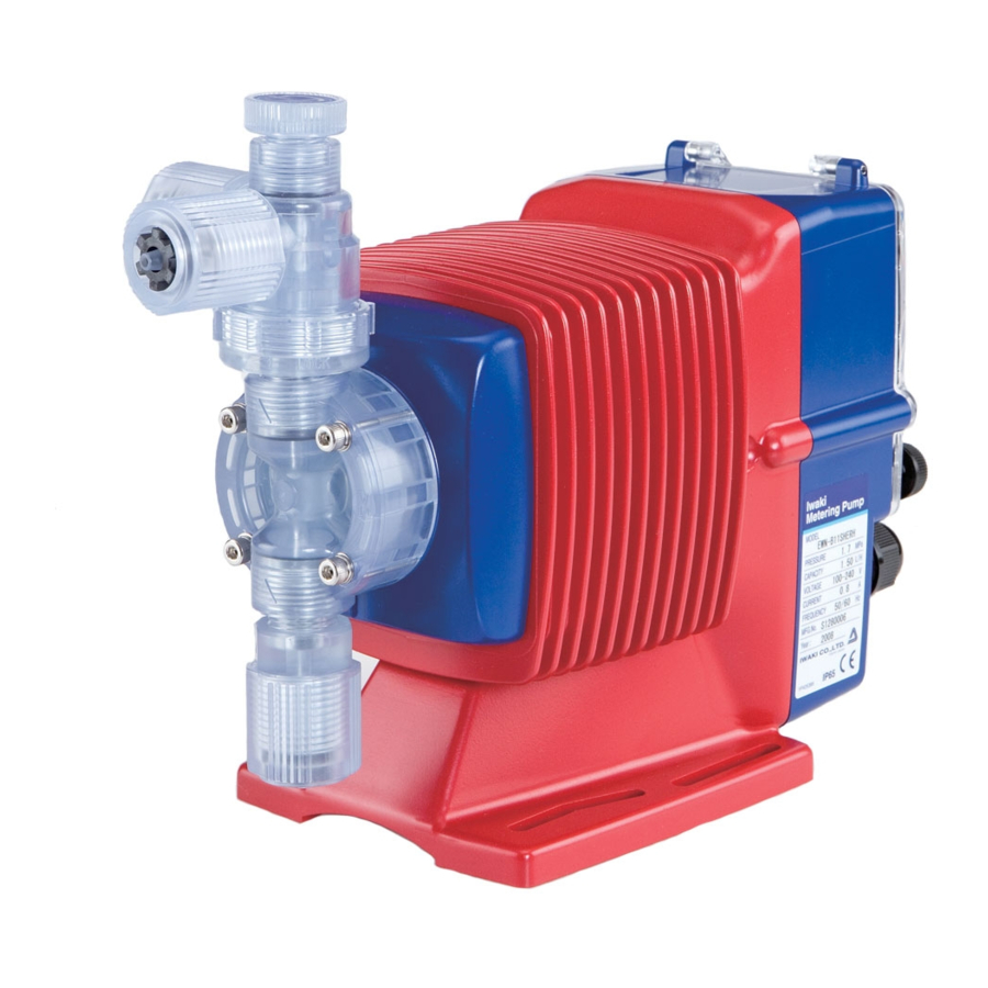
- Page 12 Overview The information such as characteristics, features and part names are described in this section. Pump structure & Operating principle The EWN-W is a diaphragm type electromagnetic metering pump which auto- matically monitors and controls water quality by means of a sensor.
- Page 13 Features Operational functions SP.2 SP.1 mg/L 0.4 0.6 0.8...
- Page 15 mg/L mg/L 0.70 0.80 0.90 0.10 0.20 0.30...
- Page 18 Pump...
- Page 19 Operational panel...
- Page 20 Error oc...
- Page 21 The model codes of the pump/drive units and the control unit represent the fol- lowing information. Pump/Drive units EWN - B 11 VC E WCL...
- Page 23 • • •...
- Page 25 Installation This section describes the installation of the pump, tubing and wiring. Read through this section before work. • • • Select an installation location and mount the pump. • NOTE...
- Page 26 Connect tubes to the pump and install a check valve. Tube connection...
- Page 28 Check valve mounting Install an optional check valve to the EWN siphon and overfeeding. In the following cases be sure to install the check valve. • • The •...
- Page 29 R1/2 Outer dia ø9 R3/8 NOTE NOTE...
- Page 30 • Where ° ° • • • • • • • • • • ° 0±2°...
- Page 31 Flow cell mounting NOTE • • •...
- Page 32 FRC sensor mounting a leak.
- Page 33 Beads loading Remove the body from the head and load it with beads. Always remove all ring is in place and then mount the body into the head. NOTE •...
- Page 34 • • • • •...
- Page 35 End terminals See the following diagram for detail. Power voltage/Earthing...
- Page 36 NOTE • • POWER POWER TIME TIME • •...
- Page 37 • • • • Signal wire connection Purchase the following DIN 4- and 5-pin female connector cables when using signal input and output. Binder round connector cables Hirschmann square connector cables •...
- Page 38 NOTE • • • • • When using an open collector: • When using a contact: NOTE •...
- Page 39 • When using an open collector: • When using a contact: • • chronous output.
- Page 40 Sensor cable connection • NOTE • • • • • • Remove the terminal case and pass the sensor cable into the cable path as below.
- Page 42 Operation This section describes pump operation and programming. Run the pump after pipework and wiring is completed. adjustment before starting operation. Points to be checked Before operation, check if: •...
- Page 43 ° Degassing performance can not be obtained with gas in the pump. Conduct degassing in the following cases. NOTE • •...
- Page 44 NOTE •...
- Page 45 • • * The • • •...
- Page 46 Before a long period of stoppage (One month or more) • • • • • NOTE •...
- Page 47 Select a proper mode to make optimal operation. AUTO or MAN AUTO AUTO or MAN AUTO ON or OFF ON or OFF ON or OFF ON or OFF SENS ON or OFF 0000...
- Page 48 Keypad lock Power ON 3sec Auto operation Enter PIN number. Operating state Wait state Liquid temperature 1sec 1sec 1sec 1sec Priming mode Calibration mode User mode...
- Page 49 Perform a calibration In calibration mode, adjust a reading of the control unit along with the actual concentration of free residual chlorine. • • • • • • Adjustment • Zero adjustment...
- Page 50 NOTE...
- Page 53 User mode when returning to the wait start.
- Page 54 AUTO/MAN selection Menu selection AUTO operation MAN operation keys...
- Page 55 Control parameter programming Menu selection Process value at SP.1 keys Enter a to enter value. process value. SPM at SP.1 Enter spm. Enter process values and spm at Process value at SP.2 Enter a process value. SP.1 and SP.2 for proportional control.
- Page 56 Menu selection Measured value adjustment Adjust measured values. See page 57 for detail. *Adjustable range for deviation is between -1.00 - 1.00. AUTO/MAN TC selection Select AUTO or MAN temperature compensation. See page 57 for detail. Temperature reading adjustment /Temperature setting Adjust temperature in AUTO temperature compensation.
- Page 57 • keys to change values. • AUTO keys to change menus. • keys to change values. *Setting range is -10.0 - 10.0ºC • keys to change values. *Setting range is 0.0 - 99.0ºC.
- Page 58 Menu selection STOP function Program ON-OFF operation via the STOP signal. See page 59. Interlock function Program ON-OFF operation via the interlock signal. See page 59. OUT1 Program alarm output. See page 60. Programing menus will be added OUT1 depending on OUT1 setting. setting menu OUT2...
- Page 59 • keys to change menus. • Interlock function keys to change menus.
- Page 60 • OUT1 Upper alarm Lower alarm OUT2 Batch alarm Synchronous output (OUT2 only) Not used keys to change menus.
- Page 61 • Menu selection OUT1 or 2 Upper limit Hysteresis keys to enter value. Additional menus will appear after Delay time OUT1 or 2. keys to scroll thorough menus.
- Page 62 Menu selection OUT1 or 2 Lower limit Hysteresis keys to enter value. Additional menus will appear after Delay time OUT1 or 2. keys to scroll thorough menus.
- Page 63 Menu selection OUT1 or 2 Interlock STOP keys to select ON/OFF. Additional menus will appear after PreSTOP OUT1 or 2. Sensor failure keys to scroll thorough menus.
- Page 64 Stroke rate keys to chagne units. Measured value keys to scroll thorough menus. NOTE...
- Page 65 Entry screen Pine number entry Push key to move to next digit. Push key to change values.
- Page 66 Read this section before operation. AUTO operation The pump monitors and controls process solution automatically.
- Page 67 MAN operation Run or stop operation manually. Priming function...
- Page 68 Keypad lock Keypad lock can be active for the prevention of erroneous key operation. NOTE...
- Page 70 Maintenance This section describes troubleshooting, sensor maintenance, • • • NOTE • • •...
- Page 71 First check the following points. If the following solutions do not help remove problems, contact us or your nearest distributor. • • • • • • • • • • • • • • • • • • • • •...
- Page 72 • • • • • • • • • • • • • • • • • • •...
- Page 73 • • • • • • • • • • • • • • • • • • • • •...
- Page 74 Error codes will be shown when this product is in a faulty condition. See below for the meanings of error codes and countermeasures. Error • • • • • • • • • • • • • • • • error...
- Page 75 Conduct maintenance work periodically to keep the best performance. NOTE • •...
- Page 76 Perform daily and periodic inspections to keep pump performance and safety. Daily inspection (Pump) ately and remove problems according to "Troubleshooting". When wear parts come to the life limit, replace them with new ones. Contact us or your nearest distributor for detail. •...
- Page 77 Daily inspection (Flow cell) reach the level, it may be the sign of clogging or jamming. In this case FRC and the beads are far beyond the level, a FRC reading will be higher than an actual concentration and the life of sensor may shorten.
- Page 78 NOTE • • • • • •...
- Page 79 NOTE • • • •...
- Page 80 NOTE...
- Page 81 To run the pump for a long period, wear parts need to be replaced periodically. It is recommended that the following parts are always stocked for immediate replacement. Contact us or your nearest distributor for detail. • • • Wear part list (Pump)
- Page 82 Before replacement First release pressure from the pump head. NOTE NOTE Valve set replacement • • •...
- Page 84 NOTE...
- Page 85 Diaphragm replacement • • • NOTE...
- Page 87 NOTE • •...
- Page 88 Wear part list (Flow cell/ FRC sensor)
- Page 89 Pump head, Drive unit & Control unit The pump in the diagram below is completely dismantled. Do not dismantle the...
- Page 90 Pump head EWN- [VC•VH]...
- Page 91 Check valve...
- Page 92 Flow cell RF-20...
- Page 93 Information in this section is subject to change without notice. VC•VH VC• °...
- Page 94 OUT2...
- Page 95 end code...
- Page 96 Outer dimensions EWN-[B11•B16•B21•C16•C21] [VC• (30) (292) (47) LOCK (23) (98) EWN-[B31•C31] [VC•VH] (30) (295) (48) LOCK (98) (25)
- Page 97 EWN-C36 [VC•VH] (30) (294.5) (48) LOCK (24) (98)
- Page 100 TEL: +81 3 3254 2935 FAX: +81 3 3252 8892 / IWAKI Europe GmbH Norway / IWAKI Norge AS Australia / IWAKI Pumps Australia Pty Ltd. TEL: +49 2154 9254 0 FAX: +49 2154 9254 48 TEL: +47 23 38 49 00 FAX: +47 23 38 49 01...
Need help?
Do you have a question about the EWN-WCL and is the answer not in the manual?
Questions and answers