Advertisement
Quick Links
Iwaki
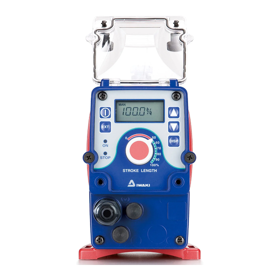
Electromagnetic Metering Pump
EWN-R (Standard)
Instruction manual
Thank you for choosing our product.
Please read through this instruction manual before use.
This instruction manual describes important precautions and
instructions for the product. Always keep it on hand for quick
reference.
2008 IWAKI CO., LTD.
Advertisement

Subscribe to Our Youtube Channel
Related Manuals for IWAKI PUMPS EWN-R


Summary of Contents for IWAKI PUMPS EWN-R
- Page 1 Iwaki Electromagnetic Metering Pump EWN-R (Standard) Instruction manual Thank you for choosing our product. Please read through this instruction manual before use. This instruction manual describes important precautions and instructions for the product. Always keep it on hand for quick reference.
- Page 2 Open the package and check that the product conforms to your order. If any problem or inconsistency is found, immediately contact your distribu- tor. a. Check if the delivery is correct. Check the nameplate to see if the information such as model codes, dis- charge capacity and discharge pressure are as ordered.
- Page 3 Contents Safety instructions ............... 6 ......................7 ......................8 ..................10 Overview ..................12 .....................12 .......................19 ..................23 Installation .................. 25 ....................25 ......................26 ......................30...
- Page 4 Operation ..................37 .....................37 ................45 Maintenance ................76...
- Page 5 ..................... 77 ....................... 79 .................. 80 ....................88 EWN FC ..............97...
- Page 6 Safety instructions Read through this section before use. This section describes important information for you to prevent personal injury or property damage. WARNING CAUTION Requirement Wear Grounding Caution Electrical Prohibited Do not rework protection shock or alter...
- Page 7 WARNING Electrical shock Requirement Prohibited Do not rework or alter Wear protection Prohibited Prohibited WARNING...
- Page 8 CAUTION Requirement Prohibited Caution Prohibited Caution Prohibited Requirement 8 CAUTION...
- Page 9 Prohibited Grounding Electrical shock Requirement Prohibited Requirement Caution Caution CAUTION...
- Page 10 Caution – Where Caution Caution Caution Caution...
- Page 11 Caution Caution Caution Requirement Caution...
- Page 12 Overview The information such as characteristics, features and part names are described in this section. Pump structure & Operating principle The EWN series is a diaphragm metering pump which consists of a pump head, drive unit and control unit. A diaphragm is directly driven by electromag- netic force.
- Page 13 LOCK...
- Page 14 Features Operational functions Key operation (Push key) Pump operation Stop Stop...
- Page 15 Pulse signal input Pump operation 1 2 3 4 5 1 2 3 4 5 Pulse signal input Pump operation 1 2 3 4 5 1 2 3 4 5 1 2 3 4 5 1 2 3 Pulse signal input 1 2 3 4 5 1 2 3 4 5 1 2 3 4 5 Pump operation...
- Page 16 100% 20mA 100% 20mA...
- Page 17 STOP signal input Pump operation Stop STOP signal input Pump operation Stop Stop...
- Page 18 Pulse signal input Pump operation 1 2 3 4 5 1 2 3 1 2 3 4 5 1 2 3...
- Page 19 Pump...
- Page 20 Operational panel MULT ANA. RV OVER P1 2 LOCK Disp DISP STOP...
- Page 21 MULT ANA. R ANA. V...
- Page 22 MULT LOCK...
- Page 23 The model codes of the pump/drive units and the control unit represent the fol- lowing information. Pump/Drive units EWN - B 11 VC f g h Code GFRPP PTFE PTFE PCTFE SUS316 SUS316 Code VC-S6 SUS316...
- Page 24 code*¹ EWN-31 *¹ ø ø ø ø ø ø ø ø8...
- Page 25 Installation This section describes the installation of the pump, tubing and wiring. Read through this section before work. Select an installation location and mount the pump. NOTE...
- Page 26 Connect tubes to the pump and install a check valve. Tube connection...
- Page 27 NOTE...
- Page 28 Check valve mounting Install an optional check valve (or a back pressure valve to the FC type) on the following cases be sure the check valve is installed. NOTE...
- Page 29 NOTE...
- Page 30 Wiring for a power voltage and an external signal. Power voltage/Earthing...
- Page 31 NOTE POWER POWER TIME TIME...
- Page 32 Signal wire connection Use DIN 4- or 5-pin female connector cables. We recommend the use of Binder connector cables (German manufacturer). Contact us for detail. Binder connector cables 5-pin : 713 series 99-0436-10-05 Input signals 4-pin : 715 series 99-0430-15-04 Level sensor signal Connect these cables according to the following procedures.
- Page 33 NOTE ø4 - ø...
- Page 34 When using an open collector: When using a contact: PUMP NOTE...
- Page 35 When using an open collector: When using a contact:...
- Page 37 Operation This section describes pump operation and programming. Run the pump after plumbing and wiring are completed. adjustment before starting operation. Points to be checked Before operation, check if: EWN-B31 EWN-C31 EWN-C36...
- Page 38 ° Degassing The gas needs to be expelled from the pump and tubing by degassing. Normal performance can not be obtained with gas in the pump. Conduct degassing in the following cases. NOTE...
- Page 39 STOP...
- Page 40 STOP STOP STOP STOP STOP STOP...
- Page 41 Flow rate adjustment...
- Page 42 Fixed stroke rate Fixed stroke rate Stroke rate is fixed at 100% Stroke rate is fixed at 100% Stroke rate is fixed at 75% Stroke rate is fixed at 75% Stroke rate is fixed at 50% Stroke rate is fixed at 50% Stroke length adjustment Stroke length adjustment Fixed stroke length...
- Page 43 STOP STOP STOP...
- Page 44 Fixed stroke rate Stroke length adjustment NOTE STOP STOP...
- Page 45 Before a long period of stoppage (One month or more) Operation at each mode is individually set and controlled by keypad operation. Select a proper mode to make optimal operation. XNNNN 1-9999 1-9999 4-20 ANA-R STOP 00000 00000-99999...
- Page 46 Power ON Calibration mode Manual mode 3 sec. Stroke rate setting EXT mode Manual operation Save Cancel MULT ANA. V Prime mode 1 sec. ANA.R Flow rate display ANA-V ANA-R programming routine programming routine Keypad lock ANA. V ANA.R Disp ANA.
- Page 47 3 sec. User mode EXT mode programming EXT mode selection MULT See ANA-V programming routine See ANA-R programming routine 2 LOCK...
- Page 48 Manual operation STOP STOP STOP...
- Page 49 STOP STOP EXT operation The pump operation is controlled by the external (pulse) signal. NOTE STOP...
- Page 50 ode. MULT STOP STOP NOTE...
- Page 51 NOTE STOP STOP STOP STOP...
- Page 52 MULT STOP STOP Disp SET MULT MULT Disp SET Disp SET MULT STOP Disp SET STOP MULT STOP STOP...
- Page 53 NOTE MULT STOP STOP MULT STOP STOP...
- Page 54 STOP STOP STOP STOP STOP STOP...
- Page 55 MULT STOP STOP MULT STOP STOP ANA. V STOP STOP...
- Page 56 ANA. V ANA. V STOP Disp SET STOP ANA. V ANA. V STOP Disp SET STOP ANA. V ANA. V STOP STOP Disp SET ANA. V STOP Disp SET STOP...
- Page 57 ANA. V STOP STOP MULT STOP STOP MULT STOP STOP...
- Page 58 ANA.R STOP STOP ANA.R STOP STOP ANA.R STOP STOP...
- Page 59 User mode The following features can be programmed. Get access to User mode via the wait state in the manual mode. NOTE...
- Page 60 STOP STOP STOP...
- Page 61 STOP STOP STOP STOP...
- Page 62 STOP STOP STOP...
- Page 63 STOP STOP STOP...
- Page 64 STOP STOP STOP...
- Page 65 STOP STOP STOP STOP...
- Page 66 NOTE STOP STOP STOP...
- Page 67 STOP STOP STOP STOP...
- Page 68 NOTE STOP STOP STOP...
- Page 69 STOP STOP STOP STOP...
- Page 70 NOTE STOP STOP STOP...
- Page 71 STOP STOP 2 LOCK 2 LOCK 2 LOCK STOP 2 LOCK STOP...
- Page 72 Keypad lock Keypad lock can be active in the following states for the prevention of errone- ous key operation. STOP STOP MULT STOP STOP ANA-R ANA- V STOP STOP NOTE...
- Page 73 STOP STOP LOCK STOP LOCK STOP LOCK STOP LOCK STOP LOCK LOCK...
- Page 74 Calibration mode Entering a liquid volume per shot, operation can be monitored in GPH, L/h or mL/m. STOP STOP STOP STOP STOP...
- Page 75 STOP 2 LOCK STOP Unit change GPH, L/h or mL/m cycles through every time the DISP key is pushed. To dure. spm indication The screen shows an actual spm in operation when both the EXT and DOWN keys are pressed for 3 seconds. 0spm will be shown after the pump has stopped.
- Page 76 Maintenance This section describes troubleshooting, inspection, wear part NOTE...
- Page 77 First check the following points. If the following measures do not help remove problems, contact us or your nearest distributor.
- Page 79 Perform daily and periodic inspection to keep pump performance and safety. Daily inspection Check the following points. Upon sensing abnormality, stop operation immedi- ately and remove problems according to "Troubleshooting". When wear parts come to the life limit, replace them with new ones. Contact us or your nearest distributor for detail.
- Page 80 To run the pump for a long period, wear parts need to be replaced periodically. It is recommended that the following parts are always stocked for immediate replacement. Contact us or your nearest distributor for detail. Wear part list 8000 34 33 30 34...
- Page 81 Before replacement First release pressure from the pump head. NOTE NOTE Valve set replacement...
- Page 83 NOTE...
- Page 85 Diaphragm replacement NOTE...
- Page 87 NOTE EWN-B09 EWN-B31 EWN-C31 EWN-C36...
- Page 88 Pump head, Drive unit & Control unit The pump in the diagram below is completely dismantled. Do not dismantle the pump beyond the extent shown in this instruction manual.
- Page 89 Pump head...
- Page 97 Information in this section is subject to change without notice. EWN-B11 EWN-B16 50-100 EWN-B21 EWN-B31 EWN-C16 EWN-C21 40-100 EWN-C31 EWN-C36 EWN-B11 EWN-B16 50-100 EWN-B21 EWN-B31 EWN-C16 EWN-C21 40-100 EWN-C31 EWN-C36...
- Page 98 EWN-B09 EWN-B11 50-100 EWN-B16 EWN-B21 EWN-C16 40-100 EWN-C21 50-100 EWN-B11 40-100 EWN-C16 70-100 EWN-B11 40-100 EWN-C31 EWN-B11 50-100 EWN-B16 EWN-C16 40-100 EWN-C21...
- Page 99 0-60 C AS3191...
- Page 100 Outer dimensions (265) (47) (68) (23) (267) (48) LOCK (68) (125) (25)
- Page 101 (265) (47) LOCK (68) (23) (267) (48) LOCK (68) (125) (25)
- Page 102 (267) (48) LOCK (68) (24) (231) (13) (68) (23)
- Page 103 (236) (16) (68) (25) (231) (13) (68) (23)
- Page 104 (236) (16) (68) (25) (235) (16) (68) (24)
- Page 105 (265) (47) LOCK (68) (23) (267) (48) LOCK (68) (25)
- Page 106 (265) (47) LOCK (68) (23) (267) (48) LOCK (68) (25)
- Page 107 (268) (49) LOCK (68) (24) (232) (15) (68) (22)
- Page 108 (233) (15) (68) (23) (232) (15) (68) (22)
- Page 109 (233) (15) (68) (23) (233) (15) (68) (23)
- Page 110 (265) (47) LOCK (68) (23) (265) (47) LOCK (68) (23)
- Page 111 (279) (62) LOCK (68) (23) (279) (62) LOCK (68) (23)
- Page 112 (232) (15) (68) (22)
- Page 113 (238) (20) (68) (23) (265) (47) AIR(AUTO) LOCK (68) (23)
- Page 114 (265) (47) AIR(AUTO) LOCK (68) (23)
- Page 115 EWN SERIES EN ISO12100 EN61000-6-2 EN50581 EN809 EN61000-6-3 IS-51K-520-1...
- Page 116 TEL: +81 3 3254 2935 FAX: +81 3 3252 8892 / IWAKI Europe GmbH Norway / IWAKI Norge AS Australia / IWAKI Pumps Australia Pty Ltd. TEL: +49 2154 9254 0 FAX: +49 2154 9254 48 TEL: +47 23 38 49 00 FAX: +47 23 38 49 01...
Need help?
Do you have a question about the EWN-R and is the answer not in the manual?
Questions and answers