
Related Manuals for IWAKI PUMPS EH-B10


Summary of Contents for IWAKI PUMPS EH-B10
- Page 1 IWAKI Electromagnetic Metering Pump EH-W Type Instruction Manual Read this manual before use of product...
-
Page 2: Table Of Contents
Thank you for having selected of Iwaki's EH/W type electromagnetic metering pump. This instruction manual, which is divided into 5 sections, namely "Safety Section," "Outline Section," "Installation Section," "Operation Section" and "Maintenance Section," deals with the correct handling and operation procedures for the pump. You are requested to read this manual prior to using the pump, to ensure safe and long operation. -
Page 3: Important Instruction
Important Instruction For the Safe and Correct Handling of the Pump • Read the "Safety Instructions" sections carefully to prevent accidents involving your customers or other personnel and to avoid damage or loss of other assets. Always follow the instructions and advice found in these sections. -
Page 4: Safety Section
Safety Section WARNING • Turn off the power supply. Working without disconnecting the power supply may cause an electrical shock. Before engaging upon any working procedures involving the pump, make sure to Electrical Shock turn the power supply switch off and to stop the pump and other related devices. •... - Page 5 Safety Section CAUTION • Do not run the pump dry. Do not run the pump dry (without liquid inside the pump). Heat generated as a result of abrasion between elements inside the pump during operation without liquid Prohibited may damage the inside of the pump. •...
- Page 6 Safety Section CAUTION • Follow the instruction manual Replace the consumable parts by following the descriptions in the instruction manual. Do not disassemble any part of the pump if the disassembling procedure for the part in question is not included in the instruction manual. •...
-
Page 7: Outline Of Product
OUTLINE OF PRODUCT 1. Unpacking and Inspection ....6 2. Operation Principle ......6 3. Identification Codes ......7 4. Main Features ........9 5. Specifications ........10 6. Description of Parts ......12 - 5 -... -
Page 8: Unpacking And Inspection
1. Unpacking and Inspection After unpacking the pump, check the following Iwaki points to ascertain that the product is exactly as you Metering Pump ordered. If you find anything wrong, please get in Discharge CAPACITY touch with your dealer. Discharge pressure mR/min MAX.PRESSURE Voltage... -
Page 9: Identification Codes
3. Identification Codes Pump Body EH - B 20 VC - 100 P W 1 - PH M M t y u i q Series code w Drive unit type (average of power consumption) B: 16W C: 24W e Effective diameter of diaphragm 10: 10mm 15: 15mm 20: 20mm... - Page 10 o Control function type * PH: pH type (pH control function, A.T.C: positive thermistor 6.8Ω at 25 ºC) PH1: pH type (pH control function, A.T.C: Pt1000) * PH2: pH type (pH control function, A.T.C: Pt100) PH2B: pH type (pH control function, A.T.C: Pt100 with BNC plug) ORP type (oxidation-reduction potential control function) Conductivity type (conductivity control function) *!0 Special specification code...
-
Page 11: Main Features
4. Main Features Control unit Controls pump operation, flow rate and • adjustment, and setting of the stroke rate. Stroke length control unit Adjusts or sets the discharge per stroke in the range of 0 to 100%. • Pump unit Reciprocating movement of the diaphragm •... -
Page 12: Specifications
VC/VH Capacity Capacity Max.pressure Stroke frequency Stroke length Average power PC/PH [ml/min] [ml/stroke] [MPa] [spm] [%](mm) consumption[W] 40 ~ 100 EH-B10 0.04-0.11 0.98 (0.4~1.0) EH-B15 0.04-0.19 0.69 20 ~ 100 EH-B20 0.06-0.29 0.39 (0.2~1.0) 0 ~ 360 EH-B30 0.13-0.64 0.20 EH-C15 0.05-0.25... - Page 13 Specifications of Control Unit Code AUTO AUTO AUTO Mode Mode Entering by keys Change KAUTO KAUTO KAUTO • SET • SET • SET 0~14pH -1999~+1999mV 0~9.99mS/cm • PB • PB • PB -14~14pH -1999~+1999mV -9.99~9.99mS/cm • spm 0~360spm • spm 0~360spm •...
-
Page 14: Description Of Parts
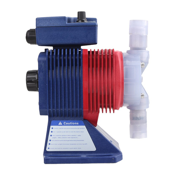
6. Description of Parts Names of Parts Control unit Pump unit Stroke rate adjusting dial Drivel unit Control unit Unit display Display panel Remains lit while the temperature Set values and error display is selected. This display is messages are displayed. not provided on the "OR"... - Page 15 Basic display patterns Display pattern Description AUTO mode operation is under way. The value may be 0 spm with the pump operation suspended, depending on the set value and the °C AUTO measured value. ZERO SPAN The pump is in standby condition in MAN mode.
-
Page 16: Installation
INSTALLATION 1. Before Use ........15 2. Notes on Operation ......15 3. Installation, Piping, and Wiring ..18 - 14 -... -
Page 17: Before Use
1. Before Use “Strictly observe the following points.” Operators and maintenance service staff must read the instruction manual thoroughly before using the products. Do not operate the pump system unless all of the contents in the manual are completely understood. Caution Turn off the power supply. - Page 18 • The pump can be operated outdoors, as the pump employs a simple water and dust proof structure. When installing the pump, avoid places exposed to direct sunlight or direct rain with an ambient temperature of above 40ºC, or with a relative humidity of above 85%.
- Page 19 • Arrange grounding! Do not operate the pump without connecting the grounding wire. Other wise, an electrical shock may result. Make sure the grounding wire is connected with the grounding terminal. • Limited operating site and storage Do not install or store the pump in the following places: Places where a flammable gas or material is used or stored.
-
Page 20: Installation, Piping, And Wiring
3. Installation, Piping, and Wiring Installation z Installation Install the pump at a place where the ambient temperature does not exceed 40ºC and the relative humidity does not exceed 85%. (There should be no dew condensation inside the control unit.) The place should be convenient for future maintenance and inspection. - Page 21 Piping z Piping of pump fittings tube For discharge side and suction side piping, use the tube provided. The connections should be firm enough to prevent liquid leakage or air suction. Fitting nut • Since the fitting nuts are made of plastic, take care not to tighten them excessively, or damage may occur to Fitting the fittings...
- Page 22 w If the pressure on the suction side is higher than that on the discharge side (Fig. B). e The liquid surface on the discharge side liquid is higher than that of the suction side, but the difference between the two levels is 5 m or less (Fig. r The load pressure (pipie resistance, discharge pump head, etc.) applied to the pump is 0.13 MPa {1.3 kgf/cm...
- Page 23 I. Wiring Caution Only the operator/service staff who is trained for safety handling procedures should be in charge of the related electric arrangement and control of the power source. Failure to observe this instruction may result in injury to personnel or damage to property. Points to be checked before wiring z Make sure that the main power switch is in OFF position (or power supply is disconnected).
- Page 24 v Make sure to establish a ground. b Do not obtain a power supply from the same power service outlet that also supplies power to high-power electric equipment which generates surge voltage which results in a malfunction of the electric circuits in the control unit.
- Page 25 Wiring • Names of parts • Connection of pH or ORP electrode <When Iwaki SensorRex is used> Set the respective wiring terminals of the pH electrode as shown in the figure. Check the terminals with the respective tags attached for a GLASS correct connection.
- Page 26 Caution All the wires are prepared especially for the control unit. Do not attempt to modify or extend them, for such a attempt may affect measurement accuracy. Caution If a wire needs to be extended, make sure to use a relay box. Connect the wires within the relay box correctly. <When an electrode of another manufacturer is used>...
- Page 27 • When a recording output (recorder) is used The recorder will output in the range of DC0 through 1V for the measurement ranges of respective device models. The connected load should be 10 kΩ or more. Take the same wiring as in the case of the stop function above. Connect wires to the connectors "5"...
-
Page 28: Pump Operation
PUMP OPERATION 1. Operation ......... 27 2. Methodsn of Pump Operation ..33 - 26 -... -
Page 29: Operation
1. Operation Test run (air bleeding to adjustment of discharge) When the pump installation, piping and wiring have been comleted and the operating procedure has been fully understood, preparations for pump operation should be made bleeding the air and adjusting the discharge. * For the operating procedure, refer to 'Methods of Pump Operation' on page 33. - Page 30 c Press the key to select "MAN." Then, "WAIT" F U N C will be displayed. °C AUTO ZERO SPAN START START F U N C F U N C S T O P S T O P v Press the START key once.
- Page 31 Procedure for air bleeding in EH-B10, 15, 20, C15, and 20 types z Open the air vent valve to put the pump in operation. The air vent valve can be opened when the air vent adjusting screw is turned counterclockwise (about haif a rotation).
- Page 32 Adjustment of Discharge The set values of the stroke length and stroke rate should be determined with full consideration of the operating conditions of the pump and the properties of the liquid to be handled. Adjust the discharge. • There are two ways of adjusting the discharge: adjustment of stroke rate and adjustment of stroke length. •...
- Page 33 z Adjustment of stroke rate The stroke rate is set by operating the control unit keys. • Adjust the stroke rate per minute of the plunger in the range of 0 to 360 spm by the control unit. Fixed stroke rate Adjusted stroke length x Adjustment of stroke length The stroke length is adjusted by changing the degree of...
- Page 34 Starting Loaded Operation When air bleeding and discharge adjustment have been completed, the pump is ready for loaded operation. See that the entire setting is complete, then start pump operation by pressuing the key. * For the operating and setting procedures, refer to 'Methods of Pump Operation' on page 33. Suspension of Operation •...
-
Page 35: Methods Of Pump Operation
2. Methods of Pump Operation The operating profile and the discharge amount of EH Series Pump (for water treatment process) is controlled by the control unit (with the contents of setting input or changed as necessary). Functions differ the selected operation mode. Read this section carefully before actual operation. Page Manual Operation ·······························································34 II. -
Page 36: Manual Operation
I. Manual Operation Start-up and Stop • Starting up procedure Before applying power, check the specified power supply on the nameplate. Caution Never use a power source other than the specified one. This will prevent trouble or damage. z Power supply When power is supplied, all display elements light up once. -
Page 37: Setting And Changing Of Modes
II. Setting and Changing of Modes Setting and Changing of Modes • MAN' and 'AUTO' modes are available for selection. MAN mode:··················· Manual operation (for air elimination or test run) AUTO mode: ················· pH control operation with PH model ORP control operation with OR model Conductivity control operation with CD model z Stop the pump through key operation and put it in standby condition (with 'WAIT' displayed). -
Page 38: Calling Up, Setting And Changing Of Parameters
III. Calling Up, Setting and Changing of Parameters Parameters Parameters, data which determine the operation and control of pump, store respective set values specified previously. The applicable parameteres available in each model and each mode are as shown below. PH model OR model CD model Mode... - Page 39 Changing parameter z Call up a parameter to be changed. Press the to display a parameter to be changed. °C AUTO ZERO SPAN START START F U N C F U N C S T O P S T O P x Press the key to start the set value display section flashing.
-
Page 40: Of Electrode
b With the desired value displayed, press the F U N C to enter the value. (The set value display section stops flashing.) °C AUTO ZERO SPAN n When setting a parameter with a minus sign, call up the parameter and press the key first. - Page 41 b Press the key to enter the value. The display F U N C stops flashing. With the above step completed, the signal from the pH °C AUTO electrode and set value are memorized. ZERO SPAN n Press the key to call up parameter SPAN. Place the pH electrode in the pH4 standard liquid for 1 to 2 minutes.
- Page 42 <Calibration for OR type> z Press the key to call up parameter ZERO. x Disconnect the wire once before connecting an ORP °C AUTO electrode or after connecting it and short-circuit the ZERO SPAN terminals GLASS and REF on the terminal block. c Press the key to make the highest digit flash.
- Page 43 v The temperature compensation coefficient is set at 2%/°C for standard operation. mS/cm °C AUTO CELL Handling instructions for pH/ORP electrodes and conductivity sensor <pH/ORP electrode> • Refer to the "Wiring" section and make sure to carry out calibration with the standard liquid. •...
-
Page 44: Description Of Performance
V. Setting of parameters and operation mechanism Setting of parameters and operation mechanism (PH model) Parameter q SET 5.00pH w PB -2.50pH e spm 300spm 2.00pH 12.00pH 6 7 8 -2.50 • Operation mechanism • The stroke rate of the pump is represented by the real line in the figure above. The range of proportional control is called proportional band (PB). -
Page 45: Other Display Messages And Special Procedure
VI. Other Display Messages and Special Procedure Error messages If any value out of the permissible set value range is entered by mistake, error indication ( 'E_ST' ) will be displayed for 5 seconds and the value valid before the °C AUTO setting change step will be resumed. - Page 46 c Press the key again to display stroke rate in flash mode. °C AUTO The above display contents are shown alternately every ZERO SPAN time the key is pressed. START START F U N C F U N C S T O P S T O P v With the desired display presented, press the F U N C...
-
Page 47: Maintenance
MAINTENANCE 1. Maintenance and Inspection ... 46 2. Causes of Trouble and Troubleshooting ........ 47 3. Disassembly and Reassembly ..48 4. Accessories........52 5. Names of Parts and External Dimensions ........53 - 45 -... -
Page 48: Maintenance And Inspection
1. Maintenance and Inspection Daily check While the pump is in operatior, pay attention to the following points. If anything is out of order, see 'Causes of Trouble and Trouble shooting' on page 46 and deal with it appropriately. When any of the parts is due for replacement, replace them with a new ones. -
Page 49: Troubleshooting
2. Causes of Trouble and Troubleshooting Trouble Cause Troubleshooting K Correct wiring. Faulty wiring or breakage. K Find cause and raise voltage Lowered voltage. Pump does not start. to rated level. K Replace electronic circuit. Damage to electronic circuit of control unit. -
Page 50: Disassemble And Reassembly
3. Disassembly and Reassembly Disassembly and Reassembly of Pump Unit Before disassembly the pump unit, as a safety measure, turn the power off and lower the pressure in the pump to atmospheric pressure. Then, remove the piping and disassemble the pump unit with reference to 'Names of Parts and Structure of Pump' on page 53. - Page 51 • Order of Valve set arrangement <Resassembly> For reassembly, follow the steps of disassembly in reverse, paying attention to the following points. • Order of arrangement and direction of insertion of valve set: An errer in the order of arranging a valve set or in the direction on its insertion will cause defective liquid feeding (leaking or a decrease in discharge).
- Page 52 Replacement of diaphragm <Disassembly> z Set the stroke length adjusting dial at 100%. x Remove the pump head from the pump unit by loosening the four hexagon socket bolts with a hexagon bar wrench. c Hold the periphery of the diaphragm and rotate it counterclockwise to detach it from the plunger pin.
- Page 53 Detachment of Control Unit * Do not detach the control unit from the pump drive unit unless unavoidable. q While operating the pump, rotate the stroke length adjusting dial to 0% reading, then stop the pump and turn off the power swtich.
-
Page 54: Accessories
Liquid Type of Fitting Pump Contacting Contacting {kgf/cm Parts of Pump Parts CA-1V-4 ◊ 6 EH-B10·15·20 ø 4 ◊ ø 6 EH-C15·20 CA-1E-4 ◊ 6 0.17 ± 0.04 {1.7 ± 0.4} CA-2V-9 EH-C30 GFRPP CA-2E-9 ø 9 ◊ ø 12 +0.04... -
Page 55: Names Of Parts And External Dimensions
5. Names of Parts and External Dimensions Exploded View Air vent assembly Key protector Control unit Stroke length adjusting dial Pump proper connector Retaining screw Valve set Body of controller Gasket Cable nut (PW-SW) Body of pump Valve set Blind cap Cable gasket Terminal box - 53 -... - Page 56 Pump Unit • EH-B10, B15, B20, C15, C20 Types Name Quantity Pump head Bracket Connecting port 1 (2) Fitting nut 3 (2) Air vent unit A 1(0) Lock nut 1(0) Diaphragm Insert bolt Retainer Air vent unit B 1(0) Valve guide...
- Page 57 EH-FC Types • Name Quantity Pump head Connecting port Fitting nut Valve gasket Valve guide Valve Valve seat Gasket Diaphragm Retainer 2 sets Valve set Note 1 Spacer Cap bolt (with spring washer and plate washer) Note 1: The number of the spacers, which are for dimensional adjustment, depends on the type of pump.
- Page 58 External Dimensions • EH-B10, B15, and B20 Types (208.5) (37) (69.5) (35) 16.5 • EH-B30 Types (192.5) (69.5) (40) 16.5 - 56 -...
- Page 59 EH-C15, and C20 Types • (231) (37) (65.5) (31) 7 16 10 • EH-C30 and C35 Types (215) (65.5) (36) 7 16 10 - 57 -...
-
Page 60: Application Of Warranty And Repair Service
Application of Warranty and Repair Service Application of warranty 1. During the warranty period, if failure or damage of product happens, despite of correct usage, because of manufac- turer’s wrong manufacturing, the failed or damaged parts are repaired free of charge by the manufacturer. 2. - Page 61 MEMO - 59 -...
- Page 62 MEMO - 60 -...
- Page 63 MEMO - 61 -...
- Page 64 TEL : (1)508 429 1440 FAX : 508 429 1386 Germany : IWAKI EUROPE GmbH TEL : (49)2154 9254 0 FAX : 2154 1028 Australia : IWAKI Pumps Australia Pty. Ltd. TEL : (61)2 9899 2411 FAX : 2 9899 2421 Italy : IWAKI Italia S.R.L.
Need help?
Do you have a question about the EH-B10 and is the answer not in the manual?
Questions and answers