Nailor 37S Manual
Low profile fan powered terminal unit with epic ecm or psc motor
Hide thumbs
Also See for 37S:
- Installation and operation manual (10 pages) ,
- Installation and operation manual (10 pages)
Table of Contents
Advertisement
Quick Links
DESCRIPTION:
• Only 11" (279) high.
• 20 ga. (1.0) galvanized
steel construction.
• 16 ga. (1.6) galvanized
steel inclined blade damper.
45° rotation. CW to close.
• Multi-point
averaging
Diamond Flow sensor.
• Access panels top and
bottom.
• 1/2"
(13)
dual
density
insulation, exposed edges
coated
to
prevent
air
erosion. Meets requirements
of NFPA 90A and UL 181.
• Single
point
electrical
and/or pneumatic main air
connection.
• Discharge
opening
for
flanged duct connection.
• Full
primary
air
valve
low voltage NEMA 1 type
enclosure
for
factory
mounted DDC and analog
electronic controls.
• Controls
mounted
as
standard on RH side as
shown. Terminals ordered
with LH controls (optional)
are inverted.
MOTOR OPTIONS:
q
Energy
efficient
PSC
fan motor with overload
protection. Solid state
fan speed controller with
minimum voltage stop.
q
Ultra-high efficiency ECM
fan
motor.
EPIC
fan
volume controller.
OPTIONS:
q
Filter frame and 1" (25)
disposable filter.
q
Toggle disconnect
switch.
q
Steri-liner.
q
Fiber-free liner.
q
Solid metal liner.
q
Perforated metal liner.
Fan unit fusing.
q
q
Hanger brackets.
q
Left-hand controls
location.
FN2 90° Line Voltage
q
Enclosure.
FN3 Remote Line
q
Voltage Enclosure
(see submittal FN3).
q
Special features
___________________.
SCHEDULE TYPE:
PROJECT:
ENGINEER:
CONTRACTOR:
Nailor Industries Inc. reserves the right to change any information concerning product or pricing without notice.
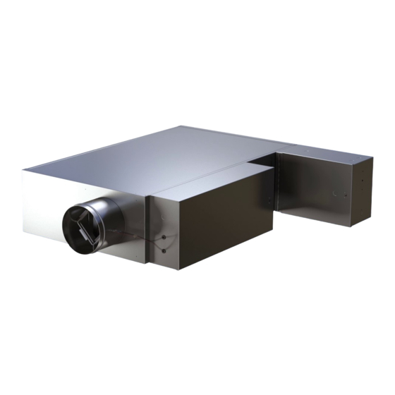
LOW PROFILE FAN POWERED TERMINAL UNIT WITH
EPIC ECM OR PSC MOTOR
SERIES FLOW • CONSTANT OR VARIABLE VOLUME
MODELS: 37S, 37SW AND 37SE • UNIT SIZES 1 – 3
Model 37S and Basic Unit
MULTI-POINT
FLOW SENSOR
PRIMARY
DIA. =
NOM. – 1/8" (3)
AIR
(203)
DRIVESHAFT
5 1/2"
(140)
Dimensional Data
Electrical Data
The EPIC ECM is a variable horsepower motor.
*
Refer to Selectworks schedule for actual power consumption.
FLA = Full load amperage. All motors are single phase/60 Hz.
6 1/4"
IW
(159)
IH
INDUCED
AIR
8"
5 4/5" (147)
14" (356)
10" (254)
OPTIONAL
90° FN2 HINGED
FAN CONTROLS
ENCLOSURE
5"
(127)
OPTIONAL
HINGED FAN
PRIMARY AIR VALVE
CONTROLS
CONTROLS
ENCLOSURE
ENCLOSURE
Page 1 of 2. For heat options; see page 2.
DATE
8 - 13 - 19
L
OPTIONAL
INDUCED AIR
INLET FILTER
2"
(51)
W
FAN
15"
(381)
6 3/4"
(171)
11"
(279)
Dimensions are in inches (mm).
B SERIES
SUPERSEDES DRAWING NO.
3700
8 - 3 - 17
DH
DW
2"
(51)
37S-1
Advertisement
Chapters
Table of Contents

Related Manuals for Nailor 37S

Summary of Contents for Nailor 37S
- Page 1 Dimensions are in inches (mm). PROJECT: ENGINEER: DATE B SERIES SUPERSEDES DRAWING NO. 8 - 13 - 19 3700 8 - 3 - 17 37S-1 CONTRACTOR: Nailor Industries Inc. reserves the right to change any information concerning product or pricing without notice.
- Page 2 Dimensions are in inches (mm). PROJECT: ENGINEER: DATE B SERIES SUPERSEDES DRAWING NO. 8 - 13 - 19 3700 8 - 3 - 17 37S-1 CONTRACTOR: Nailor Industries Inc. reserves the right to change any information concerning product or pricing without notice.
- Page 3 Dimensions are in inches (mm). PROJECT: ENGINEER: DATE B SERIES SUPERSEDES DRAWING NO. 8 - 13 - 19 3700 7 - 18 - 17 37S-2 CONTRACTOR: Nailor Industries Inc. reserves the right to change any information concerning product or pricing without notice.
- Page 4 Dimensions are in inches (mm). PROJECT: ENGINEER: DATE B SERIES SUPERSEDES DRAWING NO. 8 - 13 - 19 3700 7 - 18 - 17 37S-2 CONTRACTOR: Nailor Industries Inc. reserves the right to change any information concerning product or pricing without notice.
- Page 5 Dimensions are in inches (mm). ENGINEER: DATE B SERIES SUPERSEDES DRAWING NO. 4 - 25 - 22 3700 8 - 13 - 19 37SST-1 CONTRACTOR: Nailor Industries Inc. reserves the right to change any information concerning product or pricing without notice.
- Page 6 Dimensions are in inches (mm). PROJECT: ENGINEER: DATE B SERIES SUPERSEDES DRAWING NO. 4 - 25 - 22 3700 8 - 13 - 19 37SST-1 CONTRACTOR: Nailor Industries Inc. reserves the right to change any information concerning product or pricing without notice.
- Page 7 Dimensions are in inches (mm). PROJECT: ENGINEER: DATE B SERIES SUPERSEDES DRAWING NO. 8 - 13 - 19 3700 7 - 18 - 17 37SST-2 CONTRACTOR: Nailor Industries Inc. reserves the right to change any information concerning product or pricing without notice.
- Page 8 Dimensions are in inches (mm). PROJECT: ENGINEER: DATE B SERIES SUPERSEDES DRAWING NO. 8 - 13 - 19 3700 7 - 18 - 17 37SST-2 CONTRACTOR: Nailor Industries Inc. reserves the right to change any information concerning product or pricing without notice.
- Page 9 Dimensions are in inches (mm). PROJECT: ENGINEER: DATE B SERIES SUPERSEDES DRAWING NO. 8 - 13 - 19 3700 7 - 18 - 17 37SST-2 CONTRACTOR: Nailor Industries Inc. reserves the right to change any information concerning product or pricing without notice.
- Page 10 Dimensions are in inches (mm) PROJECT: ENGINEER: DATE B SERIES SUPERSEDES DRAWING NO. 1 - 12 - 22 8 - 3 - 21 CONTRACTOR: Nailor Industries Inc. reserves the right to change any information concerning product or pricing without notice.
- Page 11 Dimensions are in inches (mm) PROJECT: ENGINEER: DATE B SERIES SUPERSEDES DRAWING NO. CONTRACTOR: 5 - 12 - 22 VAV.ACC. 3 - 30 - 22 VAV-FDD Nailor Industries Inc. reserves the right to change any information concerning product or pricing without notice.
- Page 12 NC Impact Center Frequency (Hz) 125 1000 2000 4000 (Average) Discharge Sound Radiated Sound Fan Powered Terminal Units • 33SZ, 35N, 35S, 37N and 37S Series • All sizes. Octave Band NC Impact Center Frequency (Hz) 125 1000 2000 4000 (Average)
- Page 13 NC Impact Center Frequency (Hz) 125 1000 2000 4000 (Average) Discharge Sound Radiated Sound Fan Powered Terminal Units • 33SZ, 35N, 35S, 37N and 37S Series • All sizes. Octave Band NC Impact Center Frequency (Hz) 125 1000 2000 4000 (Average)
- Page 14 Dual Duct Terminal Units • 3230 and 3240 "Blendmaster" Series • All sizes. Nailor has independently tested and cataloged their dual duct sound data based upon the use of Steri-Liner (high density foil back insulation) rather than standard dual density fiberglass insulation as used in the above terminal units.
- Page 15 Dimensions are in inches (mm). PROJECT: DATE B SERIES SUPERSEDES DRAWING NO. ENGINEER: CONTRACTOR: 10 - 18 - 07 3500 12 - 2 - 02 35SCD-1P3 Nailor Industries Inc. reserves the right to change any information concerning product or pricing without notice.
- Page 16 SCHEDULE TYPE: Dimensions are in inches (mm). PROJECT: DATE B SERIES SUPERSEDES DRAWING NO. ENGINEER: CONTRACTOR: 10 - 17 - 07 3500 35SCD-2P3 Nailor Industries Inc. reserves the right to change any information concerning product or pricing without notice.
- Page 17 SCHEDULE TYPE: PROJECT: DATE B SERIES SUPERSEDES DRAWING NO. ENGINEER: CONTRACTOR: 12 - 2 - 02 3500 7 - 12 - 99R 35SCD-3P3 Nailor Industries Inc. reserves the right to change any information concerning product or pricing without notice.
- Page 18 ROOM TEMPERATURE INCREASE SCHEDULE TYPE: PROJECT: DATE B SERIES SUPERSEDES DRAWING NO. ENGINEER: CONTRACTOR: 8 - 6 - 08 3500 12 - 2 - 02 35SCD-A1 Nailor Industries Inc. reserves the right to change any information concerning product or pricing without notice.
- Page 19 ROOM TEMPERATURE INCREASE PROJECT: DATE B SERIES SUPERSEDES DRAWING NO. ENGINEER: CONTRACTOR: 8 - 6 - 08 3500 12 - 2 - 02 35SCD-A2 Nailor Industries Inc. reserves the right to change any information concerning product or pricing without notice.
- Page 20 ROOM TEMPERATURE INCREASE PROJECT: DATE B SERIES SUPERSEDES DRAWING NO. ENGINEER: CONTRACTOR: 8 - 6 - 08 3500 12 - 2 - 02 35SCD-A5 Nailor Industries Inc. reserves the right to change any information concerning product or pricing without notice.
- Page 21 ROOM TEMPERATURE INCREASE PROJECT: DATE B SERIES SUPERSEDES DRAWING NO. ENGINEER: CONTRACTOR: 8 - 6 - 08 3500 12 - 2 - 02 35SCD-B13 Nailor Industries Inc. reserves the right to change any information concerning product or pricing without notice.
- Page 22 ROOM TEMPERATURE INCREASE SCHEDULE TYPE: PROJECT: DATE B SERIES SUPERSEDES DRAWING NO. ENGINEER: CONTRACTOR: 8 - 6 - 08 3500 12 - 2 - 02 35SCD-B15 Nailor Industries Inc. reserves the right to change any information concerning product or pricing without notice.
- Page 23 ROOM TEMPERATURE INCREASE PROJECT: DATE B SERIES SUPERSEDES DRAWING NO. ENGINEER: CONTRACTOR: 8 - 6 - 08 3500 12 - 2 - 02 35SCD-B2 Nailor Industries Inc. reserves the right to change any information concerning product or pricing without notice.
- Page 24 ROOM TEMPERATURE INCREASE PROJECT: DATE B SERIES SUPERSEDES DRAWING NO. ENGINEER: CONTRACTOR: 8 - 6 - 08 3500 12 - 2 - 02 35SCD-B5 Nailor Industries Inc. reserves the right to change any information concerning product or pricing without notice.
- Page 25 (Thermostat includes backing plate for 2" x 4" electrical box). SCHEDULE TYPE: PROJECT: DATE B SERIES SUPERSEDES DRAWING NO. ENGINEER: CONTRACTOR: 8 - 6 - 08 3500 12 - 2 - 02 35SCD-B6 Nailor Industries Inc. reserves the right to change any information concerning product or pricing without notice.
- Page 26 Dimensions are in inches (mm). PROJECT: DATE B SERIES SUPERSEDES DRAWING NO. ENGINEER: CONTRACTOR: 10 - 18 - 07 3500 12 - 2 - 02 35SCD-QK Nailor Industries Inc. reserves the right to change any information concerning product or pricing without notice.
- Page 27 SPACE TEMPERATURE INCREASE SCHEDULE TYPE: Dimensions are in inches (mm). PROJECT: DATE B SERIES SUPERSEDES DRAWING NO. ENGINEER: CONTRACTOR: 10 - 18 - 07 3500 35SCD-QN Nailor Industries Inc. reserves the right to change any information concerning product or pricing without notice.
- Page 28 SCHEDULE TYPE: PROJECT: DATE B SERIES SUPERSEDES DRAWING NO. ENGINEER: CONTRACTOR: 10 - 18 - 07 3500 12 - 2 - 02 35SECD-1P3 Nailor Industries Inc. reserves the right to change any information concerning product or pricing without notice.
- Page 29 SPACE TEMPERATURE DECREASE SCHEDULE TYPE: PROJECT: DATE B SERIES SUPERSEDES DRAWING NO. ENGINEER: CONTRACTOR: 10 - 17 - 07 3500 35SECD-2P3 Nailor Industries Inc. reserves the right to change any information concerning product or pricing without notice.
- Page 30 SCHEDULE TYPE: PROJECT: DATE B SERIES SUPERSEDES DRAWING NO. ENGINEER: CONTRACTOR: 12 - 2 - 02 3500 9 - 12 - 99RR 35SECD-3P3 Nailor Industries Inc. reserves the right to change any information concerning product or pricing without notice.
- Page 31 ROOM TEMPERATURE INCREASE PROJECT: DATE B SERIES SUPERSEDES DRAWING NO. ENGINEER: CONTRACTOR: 8 - 6 - 08 3500 12 - 2 - 02 35SECD-A3 Nailor Industries Inc. reserves the right to change any information concerning product or pricing without notice.
- Page 32 (Thermostat includes backing plate for 2" x 4" electrical box). SCHEDULE TYPE: PROJECT: DATE B SERIES SUPERSEDES DRAWING NO. ENGINEER: CONTRACTOR: 2 - 7 - 11 3500 35SECD-A4 Nailor Industries Inc. reserves the right to change any information concerning product or pricing without notice.
- Page 33 ROOM TEMPERATURE INCREASE PROJECT: DATE B SERIES SUPERSEDES DRAWING NO. ENGINEER: CONTRACTOR: 8 - 6 - 08 3500 12 - 2 - 02 35SECD-A7 Nailor Industries Inc. reserves the right to change any information concerning product or pricing without notice.
- Page 34 ROOM TEMPERATURE INCREASE PROJECT: DATE B SERIES SUPERSEDES DRAWING NO. ENGINEER: CONTRACTOR: 8 - 6 - 08 3500 12 - 2 - 02 35SECD-B3 Nailor Industries Inc. reserves the right to change any information concerning product or pricing without notice.
- Page 35 ROOM TEMPERATURE INCREASE PROJECT: DATE B SERIES SUPERSEDES DRAWING NO. ENGINEER: CONTRACTOR: 8 - 6 - 08 3500 12 - 2 - 02 35SECD-B7 Nailor Industries Inc. reserves the right to change any information concerning product or pricing without notice.
- Page 36 (Thermostat includes backing plate for 2" x 4" electrical box). SCHEDULE TYPE: PROJECT: DATE B SERIES SUPERSEDES DRAWING NO. ENGINEER: CONTRACTOR: 8 - 6 - 08 3500 12 - 2 - 02 35SECD-B9 Nailor Industries Inc. reserves the right to change any information concerning product or pricing without notice.
- Page 37 SCHEDULE TYPE: PROJECT: DATE B SERIES SUPERSEDES DRAWING NO. ENGINEER: CONTRACTOR: 10 - 18 - 07 3500 12 - 2 - 02 35SWCD-1P3 Nailor Industries Inc. reserves the right to change any information concerning product or pricing without notice.
- Page 38 SCHEDULE TYPE: PROJECT: DATE B SERIES SUPERSEDES DRAWING NO. ENGINEER: CONTRACTOR: 12 - 2 - 02 3500 7 - 12 - 99R 35SWCD-3P3 Nailor Industries Inc. reserves the right to change any information concerning product or pricing without notice.
- Page 39 (Thermostat includes backing plate for 2" x 4" electrical box). SCHEDULE TYPE: PROJECT: DATE B SERIES SUPERSEDES DRAWING NO. ENGINEER: CONTRACTOR: 8 - 6 - 08 3500 12 - 2 - 02 35SWCD-A3 Nailor Industries Inc. reserves the right to change any information concerning product or pricing without notice.
- Page 40 (Thermostat includes backing plate for 2" x 4" electrical box). SCHEDULE TYPE: PROJECT: DATE B SERIES SUPERSEDES DRAWING NO. ENGINEER: CONTRACTOR: 8 - 6 - 08 3500 12 - 2 - 02 35SWCD-A4 Nailor Industries Inc. reserves the right to change any information concerning product or pricing without notice.
- Page 41 ROOM TEMPERATURE INCREASE PROJECT: DATE B SERIES SUPERSEDES DRAWING NO. ENGINEER: CONTRACTOR: 8 - 6 - 08 3500 12 - 2 - 02 35SWCD-A7 Nailor Industries Inc. reserves the right to change any information concerning product or pricing without notice.
- Page 42 ROOM TEMPERATURE INCREASE SCHEDULE TYPE: PROJECT: DATE B SERIES SUPERSEDES DRAWING NO. ENGINEER: CONTRACTOR: 8 - 6 - 08 3500 12 - 2 - 02 35SWCD-A8 Nailor Industries Inc. reserves the right to change any information concerning product or pricing without notice.
- Page 43 Specify ________ . SCHEDULE TYPE: PROJECT: DATE B SERIES SUPERSEDES DRAWING NO. ENGINEER: CONTRACTOR: 8 - 6 - 08 3500 12 - 2 - 02 35SWCD-B10 Nailor Industries Inc. reserves the right to change any information concerning product or pricing without notice.
- Page 44 ROOM TEMPERATURE INCREASE PROJECT: DATE B SERIES SUPERSEDES DRAWING NO. ENGINEER: CONTRACTOR: 8 - 6 - 08 3500 12 - 2 - 02 35SWCD-B4 Nailor Industries Inc. reserves the right to change any information concerning product or pricing without notice.
- Page 45 ROOM TEMPERATURE INCREASE PROJECT: DATE B SERIES SUPERSEDES DRAWING NO. ENGINEER: CONTRACTOR: 8 - 6 - 08 3500 12 - 2 - 02 35SWCD-B8 Nailor Industries Inc. reserves the right to change any information concerning product or pricing without notice.
- Page 46 SCHEDULE TYPE: PROJECT: ENGINEER: DATE B SERIES SUPERSEDES DRAWING NO. CONTRACTOR: 10 - 20 - 16 3500 12 - 2 - 15 D35N300 Nailor Industries Inc. reserves the right to change any information concerning product or pricing without notice.
- Page 47 SCHEDULE TYPE: PROJECT: ENGINEER: DATE B SERIES SUPERSEDES DRAWING NO. CONTRACTOR: 10 - 14 - 16 3500 12 - 2 - 15 D35N302 Nailor Industries Inc. reserves the right to change any information concerning product or pricing without notice.
- Page 48 SCHEDULE TYPE: PROJECT: ENGINEER: DATE B SERIES SUPERSEDES DRAWING NO. CONTRACTOR: 10 - 14 - 16 3500 12 - 2 - 15 D35N303 Nailor Industries Inc. reserves the right to change any information concerning product or pricing without notice.
- Page 49 HTG. CLG. (-1.1°C) PROJECT: ENGINEER: DATE B SERIES SUPERSEDES DRAWING NO. CONTRACTOR: 10 - 20 - 16 3500 12 - 2 - 15 D35N304 Nailor Industries Inc. reserves the right to change any information concerning product or pricing without notice.
- Page 50 2000 fpm (10.2 m/s). pressure signal from Diamond Flow Sensor on analog/digital When digital or other controls are mounted by Nailor, but supplied controls and .03" (7.5) for pneumatic controllers. This is a realistic by others, these values are guidelines only, based upon experience low limit for many transducers used in the digital controls industry.
- Page 51 Discharge Sound Table E1 of Appendix E provides typical discharge sound attenuation values for three sizes of terminal unit. The Nailor Model Series: 35S, 35SST, 37S, 37SST, 35N and 1. Small box; Less than 300 cfm (142 l/s) 37N fan powered terminal unit performance data is presented in [Discharge Duct 8"...
- Page 52 FAN POWERED TERMINAL UNITS • FAN POWERED TERMINAL UNITS • 37S SERIES Performance Data ECM Motor Fan Curves – Airflow vs. Downstream Static Pressure 37S Series • Low Profile • Series Flow Unit Size 1 Unit Size 2 l/s CFM...
- Page 53 FAN POWERED TERMINAL UNITS • FAN POWERED TERMINAL UNITS • 37S SERIES Performance Data PSC Motor Fan Curves – Airflow vs. Downstream Static Pressure 37S Series • Low Profile • Series Flow Unit Size 2 Unit Size 3 l/s CFM...
- Page 54 FAN POWERED TERMINAL UNITS • FAN POWERED TERMINAL UNITS • 37S SERIES Performance Data • AHRI Certification and Performance Notes Model Series 37S • Low Profile • Series Flow • Basic Unit • AHRI Certification Rating Points Fiberglass Liner Motor = ECM.
- Page 55 FAN POWERED TERMINAL UNITS • FAN POWERED TERMINAL UNITS • 37S SERIES Performance Data • Discharge Sound Power Levels Model Series 37S • Low Profile • Series Flow • Basic Unit Fiberglass Liner Min. inlet Fan and 100% Primary Air – Sound Power Octave Bands @ Inlet pressure ( Ps) shown...
- Page 56 FAN POWERED TERMINAL UNITS • FAN POWERED TERMINAL UNITS • 37S SERIES Performance Data • NC Level Application Guide Model Series 37S • Low Profile • Series Flow Fiberglass Liner NC Levels @ Inlet Pressure ( Ps) shown Min. inlet...
- Page 57 FAN POWERED TERMINAL UNITS • FAN POWERED TERMINAL UNITS • 37S SERIES Performance Data • Radiated Sound Power Levels Model Series 37S • Low Profile • Series Flow • Basic Unit Fiberglass Liner Min. inlet Fan and 100% Primary Air – Sound Power Octave Bands @ Inlet pressure ( Ps) shown...
- Page 58 FAN POWERED TERMINAL UNITS • 37SST SERIES Performance Data ECM Motor Fan Curves – Airflow vs. Downstream Static Pressure 37SST "Stealth " Series • Low Profile • Series Flow Unit Size 1 Unit Size 2 l/s CFM l/s CFM MAXIMUM MAXIMUM MAX.
- Page 59 FAN POWERED TERMINAL UNITS • 37SST SERIES Performance Data PSC Motor Fan Curves – Airflow vs. Downstream Static Pressure 37SST "Stealth " Series • Low Profile • Series Flow Unit Size 2 l/s CFM Unit Size 3 l/s CFM 1100 MAXIMUM MAXIMUM 1000...
- Page 60 FAN POWERED TERMINAL UNITS • 37SST SERIES Performance Data • AHRI Certification and Performance Notes Model Series 37SST "Stealth " • Low Profile • Series Flow • AHRI Certification Rating Points Fiberglass Liner Motor = ECM. Primary air valve is closed and therefore primary cfm is zero. accordance with AHRI Standards.
- Page 61 FAN POWERED TERMINAL UNITS • 37SST SERIES Performance Data • Discharge Sound Power Levels Model Series 37SST "Stealth " • Low Profile • Series Flow Fiberglass Liner Min. inlet Fan and 100% Primary Air – Sound Power Octave Bands @ Inlet pressure ( Ps) shown Airflow Fan Only Unit...
- Page 62 FAN POWERED TERMINAL UNITS • 37SST SERIES Performance Data • NC Level Application Guide Model Series 37SST "Stealth " • Low Profile • Series Flow Fiberglass Liner NC Levels @ Inlet Pressure ( Ps) shown Min. inlet Airflow Unit Inlet DISCHARGE RADIATED Size...
- Page 63 FAN POWERED TERMINAL UNITS • 37SST SERIES Performance Data • Radiated Sound Power Levels Model Series 37SST "Stealth " • Low Profile • Series Flow Fiberglass Liner Min. inlet Fan and 100% Primary Air – Sound Power Octave Bands @ Inlet pressure ( Ps) shown Airflow Fan Only Unit...
- Page 64 FAN POWERED TERMINAL UNITS • 37S/37SST SERIES Performance Data • Hot Water Coil Models: 37SW and 37SWST • Low Profile • Series Flow Unit Size 1 1 Row (single circuit) 2 Row (multi-circuit) kW MBH GPM l/s kW MBH GPM l/s...
- Page 65 FAN POWERED TERMINAL UNITS • 37S/37SST SERIES Performance Data • Hot Water Coil Models: 37SW and 37SWST • Low Profile • Series Flow Unit Sizes 2 & 3 1 Row (single circuit) 2 Row (multi-circuit) kW MBH GPM l/s kW MBH GPM l/s 13.8...
- Page 66 FAN POWERED TERMINAL UNITS • 37S/37SST SERIES Performance Data • Hot Water Coil Models: 37SW and 37SWST • Low Profile • Series Flow Unit Size 4 1 Row (single circuit) 2 Row (multi-circuit) kW MBH GPM l/s kW MBH GPM l/s 14.9...
- Page 67 FAN POWERED TERMINAL UNITS Electric Heating Coils Features, Selection and Capacities Nailor Electric Coils are tested with terminal units in accordance with UL Standard 1995 and meet all requirements of the NEC (National Electric Code) and CSA (Canadian Standards Association). Units are listed and labeled by the ETL Testing Laboratory as a total package.
- Page 68 The maximum approved discharge air temperature for any Heater Selection Chart Nailor Fan Powered Terminal Unit with supplemental heat is 120°F (49°C). No heater should be applied to exceed this Assuming 70°F inlet air temperature at heater. 115°F temperature.
- Page 69 EZvav Digital Controls www.nailor.com Date: 7-2016 Supersedes: 6-2016 IOM-EZVAVINST Nailor reserves the right to change any information concerning product or specification without notice or obligation.
-
Page 70: Table Of Contents
Quick start configuration guide - EZvav sensors & controllers . . . . . . . . . . . . . . . . . . . . . . . . . . . . .28 Date: 10-2016 Supersedes: 7-2016 IOM-EZVAVINST Page 2 of 48 Nailor reserves the right to change any information concerning product or specification without notice or obligation. - Page 71 Accessories and replacement parts . . . . . . . . . . . . . . . . . . . . . . . . . . . . . . . . . . . . . . . . . . . . . . . . . .48 Date: 10-2016 Supersedes: 7-2016 Page 3 of 48 IOM-EZVAVINST Nailor reserves the right to change any information concerning product or specification without notice or obligation.
-
Page 72: Section 1: About The Controllers
• System diagnostic indicators. • Airflow balancing. Additional topics in this section Specifications ............................5 Safety considerations ..........................7 Date: 10-2016 Supersedes: 7-2016 IOM-EZVAVINST Page 4 of 48 Nailor reserves the right to change any information concerning product or specification without notice or obligation. -
Page 73: Specifications
• Zero point accuracy 0.0008 in. H2O/0.2 Pa at 77°F (25°C). • Barbed connections for 1/4 inch (6.35 mm) FR tubing. Date: 10-2016 Supersedes: 7-2016 Page 5 of 48 IOM-EZVAVINST Nailor reserves the right to change any information concerning product or specification without notice or obligation. - Page 74 Dimensions 4.14" (54) 4.25" (108) 0.77" 1.92" (49) (19) 6.53" (166) 6" (152) 4.89" (124) Date: 10-2016 Supersedes: 7-2016 IOM-EZVAVINST Page 6 of 48 Nailor reserves the right to change any information concerning product or specification without notice or obligation.
-
Page 75: Safety Considerations
Setting the Rotation Limits Nailor EZvav controllers are manufactured for a damper that rotates 90 degrees from open to close. If the VAV damper is not a 90 degree damper, set the rotation limits to 45 or 60 degrees before mounting the controller. -
Page 76: Mounting On A Vav Terminal Unit
Mount the controller directly over the damper shaft. A minimum shaft length of 2.0 inch (51 mm) is required. Note: Nailor EZvav controllers are designed to directly mount to 3/8 to 5/8 inch (9.5 to 16 mm) round or 3/8 to 7/16 inch (9.5 to 11 mm) square damper shafts. -
Page 77: Connecting An Airflow Sensor
Digital Controller Diamond flow sensors are supplied by Nailor as part of the VAV terminal unit. If a sensor is needed, choose a sensor listed in the topic Accessories and Replacement Parts on page 48. For more information on Nailor’s ‘Diamond Flow’ Sensor, see page 48 or refer to Nailor website. -
Page 78: Connecting A Dat Sensor
BACnet MS/TP 24 VAC Class 2 24VAC Maintenance Nailor EZvav controllers require no routine maintenance. If necessary, clean with a damp cloth and mild soap. Date: 10-2016 Supersedes: 7-2016 IOM-EZVAVINST Page 10 of 48 Nailor reserves the right to change any information concerning product or specification without notice or obligation. -
Page 79: Section 3: Installing The Room Sensors
1. Turn the Allen screws in the base of the sensor clockwise until they clear the case. Swing the sensor away from the mounting base to remove it. Turn screws clockwise to remove sensor case from base. Date: 10-2016 Supersedes: 7-2016 Page 11 of 48 IOM-EZVAVINST Nailor reserves the right to change any information concerning product or specification without notice or obligation. -
Page 80: Operation
• Small animal movement. Side view Top view Motion sensor vertical and horizontal patterns Date: 10-2016 Supersedes: 7-2016 IOM-EZVAVINST Page 12 of 48 Nailor reserves the right to change any information concerning product or specification without notice or obligation. -
Page 81: Section 4: Changing The Room Set Point
2. Press the button to save the value. (%!4).' The display returns to the temperature display. Date: 10-2016 Supersedes: 7-2016 Page 13 of 48 IOM-EZVAVINST Nailor reserves the right to change any information concerning product or specification without notice or obligation. -
Page 82: Section 5: Configuring The Controllers
3 Select a configuration Access to the configuration functions always start at the CNFG display. function. Date: 10-2016 Supersedes: 7-2016 IOM-EZVAVINST Page 14 of 48 Nailor reserves the right to change any information concerning product or specification without notice or obligation. -
Page 83: Entering System Temperature Set Points And Limits
2. Press the button to save the set point and advance to the next function. Date: 10-2016 Supersedes: 7-2016 Page 15 of 48 IOM-EZVAVINST Nailor reserves the right to change any information concerning product or specification without notice or obligation. - Page 84 2. Press the button to save the set point and advance to the next function. Date: 10-2016 Supersedes: 7-2016 IOM-EZVAVINST Page 16 of 48 Nailor reserves the right to change any information concerning product or specification without notice or obligation.
-
Page 85: Configuring The Vav Terminal Unit Options
• If required, enter Password 2. The display changes to CNFG when Password 2 is correct. //// Date: 10-2016 Supersedes: 7-2016 Page 17 of 48 IOM-EZVAVINST Nailor reserves the right to change any information concerning product or specification without notice or obligation. - Page 86 2. Press the button to save the fan option and advance to the next function. Date: 10-2016 Supersedes: 7-2016 IOM-EZVAVINST Page 18 of 48 Nailor reserves the right to change any information concerning product or specification without notice or obligation.
-
Page 87: Set The Airflow Set Points
• If required, enter Password 2. The display changes to CNFG when Password 2 is correct. //// Date: 10-2016 Supersedes: 7-2016 Page 19 of 48 IOM-EZVAVINST Nailor reserves the right to change any information concerning product or specification without notice or obligation. - Page 88 Not used in all models. advance to the next function. Date: 10-2016 Supersedes: 7-2016 IOM-EZVAVINST Page 20 of 48 Nailor reserves the right to change any information concerning product or specification without notice or obligation.
-
Page 89: Advanced Options
• If required, enter Password 2. The display changes to CNFG when Password 2 is correct. //// Date: 10-2016 Supersedes: 7-2016 Page 21 of 48 IOM-EZVAVINST Nailor reserves the right to change any information concerning product or specification without notice or obligation. - Page 90 Disable The controller will remain in the occupied mode regardless of the primary air supply. Date: 10-2016 Supersedes: 7-2016 IOM-EZVAVINST Page 22 of 48 Nailor reserves the right to change any information concerning product or specification without notice or obligation.
-
Page 91: Restore Application
• If required, enter Password 2. The display changes to CNFG when Password 2 is correct. //// Date: 10-2016 Supersedes: 7-2016 Page 23 of 48 IOM-EZVAVINST Nailor reserves the right to change any information concerning product or specification without notice or obligation. -
Page 92: Section 6: Balancing Airflow
STE-8001W36 are the actual uncorrected airflow readings as measured by the controller. Tip: Once the following procedure is started, all steps must be completed in order. Date: 10-2016 Supersedes: 7-2016 IOM-EZVAVINST Page 24 of 48 Nailor reserves the right to change any information concerning product or specification without notice or obligation. - Page 93 5. Press the button to save the measured airflow. The display changes to PMIN. Date: 10-2016 Supersedes: 7-2016 Page 25 of 48 IOM-EZVAVINST Nailor reserves the right to change any information concerning product or specification without notice or obligation.
- Page 94 5. Press the button to save the measured airflow. The display advances to SEC. Date: 10-2016 Supersedes: 7-2016 IOM-EZVAVINST Page 26 of 48 Nailor reserves the right to change any information concerning product or specification without notice or obligation.
- Page 95 • EXIT to return to the temperature display. 2. Press the button to select the next function. Date: 10-2016 Supersedes: 7-2016 Page 27 of 48 IOM-EZVAVINST Nailor reserves the right to change any information concerning product or specification without notice or obligation.
-
Page 96: Quick Start Configuration Guide - Ezvav Sensors & Controllers
* Not used for all models ** Select English (factory setting) or Metric before setting other parameters. Date: 10-2016 Supersedes: 7-2016 IOM-EZVAVINST Page 28 of 48 Nailor reserves the right to change any information concerning product or specification without notice or obligation. -
Page 97: Section 7: Application Drawings
For cooling and heating, a duct temperature sensor is required for Discharge Air Temperature limiting and automatic changeover. See the topic Advanced options on page 21 for instructions to enable Discharge Air Temperature limiting. Submittal sheets for several variations of this application are available from the Resources page at www.nailor.com. Figure 7-1 Cooling or heating application drawing... -
Page 98: Staged Reheat
• The fan start circuit is a 24 volt AC pilot duty output. • The fan speed output is 0 – 10 volts DC. Submittal sheets for several variations of this application are available from the Resources page at www.nailor.com. Figure 7-2 BAC-8005-36 (Single Duct) with three-stage reheat... -
Page 99: Modulating Reheat
• The fan start circuit is a 24 volt AC pilot duty output. • The fan speed output is 0 – 10 volts DC. Submittal sheets for several variations of this application are available from the Resources page at www.nailor.com. Figure 7-3 Modulating reheat... -
Page 100: Floating Reheat
• The fan start circuit is a 24 volt AC pilot duty output. • The fan speed output is 0 – 10 volts DC. Submittal sheets for several variations of this application are available from the Resources page at www.nailor.com. Figure 7-4 Floating reheat... -
Page 101: Dual-Duct Application
This application is for a BAC-8007-36 controller. The controller is configured for Dual duct operation. Dual duct VAV requires a TSP-8001-36 actuator to be used with the BAC-8007-36 as shown in the Figure 7-5 Dual duct wiring diagram on page 33. Submittal sheets for several variations of this application are available from the Knowledge Center page at www.nailor.com. Dual duct wiring diagram... -
Page 102: Section 8: Sequences Of Operation
K-factor of the VAV terminal unit are used to calculate the airflow through the VAV unit. Date: 10-2016 Supersedes: 7-2016 EZVAVINST Page 34 of 48 Nailor reserves the right to change any information concerning product or specification without notice or obligation. -
Page 103: Occupancy Sequence
This is the set point used when the controller is occupied which is determined by primary airflow and, on controllers equipped with motion sensors, motion in the zone. Date: 10-2016 Supersedes: 7-2016 Page 35 of 48 EZVAVINST Nailor reserves the right to change any information concerning product or specification without notice or obligation. -
Page 104: Pid Control Loops
See the topic Discharge Air Temperature (DAT) limiting on page 37 and Input sources on page 34. Date: 10-2016 Supersedes: 7-2016 EZVAVINST Page 36 of 48 Nailor reserves the right to change any information concerning product or specification without notice or obligation. -
Page 105: Discharge Air Temperature (Dat) Limiting
The Need for AHU Start object changes to False (0) when both loops drop below 5%. Date: 10-2016 Supersedes: 7-2016 Page 37 of 48 IOM-EZVAVINST Nailor reserves the right to change any information concerning product or specification without notice or obligation. -
Page 106: Damper Operation
MAX FAN SPEED OCCUPIED MIN FAN SPEED UNOCCUPIED/ STANDBY FAN OFF HTG SP ROOM TEMP INCREASE Date: 10-2016 Supersedes: 7-2016 IOM-EZVAVINST Page 38 of 48 Nailor reserves the right to change any information concerning product or specification without notice or obligation. -
Page 107: Reheat Sequence
See the topic Staged reheat on page 30 for an application drawing. Table 8–1 Staged reheat thresholds Output State Heating Stage On threshold Off threshold Stage 1 Stage 2 Stage 3 Date: 10-2016 Supersedes: 7-2016 Page 39 of 48 IOM-EZVAVINST Nailor reserves the right to change any information concerning product or specification without notice or obligation. -
Page 108: Balancing Airflow Sequence
Dual Duct Minimum airflow. See the topic, Dual duct application on page 33 for an application drawing. Date: 10-2016 Supersedes: 7-2016 IOM-EZVAVINST Page 40 of 48 Nailor reserves the right to change any information concerning product or specification without notice or obligation. -
Page 109: Section 9: System Integration And Networking
Mid line controller EOL switches ON EOL switches OFF EOL switches ON Date: 10-2016 Supersedes: 7-2016 Page 41 of 48 IOM-EZVAVINST Nailor reserves the right to change any information concerning product or specification without notice or obligation. -
Page 110: Setting Up Network Communications
• If required, enter Password 2. The display changes to CNFG when Password 2 is correct. //// Date: 10-2016 Supersedes: 7-2016 IOM-EZVAVINST Page 42 of 48 Nailor reserves the right to change any information concerning product or specification without notice or obligation. - Page 111 • EXIT to return to the temperature display. 2. Press the button to select the next function Date: 10-2016 Supersedes: 7-2016 Page 43 of 48 IOM-EZVAVINST Nailor reserves the right to change any information concerning product or specification without notice or obligation.
-
Page 112: Bacnet Objects
Occupied Cooling Set point OCC HT SPT Occupied Heating Set point UNOCC CL STPT Unoccupied Cooling Set point Date: 10-2016 Supersedes: 7-2016 IOM-EZVAVINST Page 44 of 48 Nailor reserves the right to change any information concerning product or specification without notice or obligation. - Page 113 AV55 CHNG_OVER_DELAY Cooling Change Over Delay AV56 LOW AUTO OCC Low Limit for Auto Occupy Date: 10-2016 Supersedes: 7-2016 Page 45 of 48 IOM-EZVAVINST Nailor reserves the right to change any information concerning product or specification without notice or obligation.
- Page 114 CL LOOP Cooling Loop LOOP2 HT LOOP Heating Loop LOOP3 DAT Loop Discharge Air Temp Loop Date: 10-2016 Supersedes: 7-2016 IOM-EZVAVINST Page 46 of 48 Nailor reserves the right to change any information concerning product or specification without notice or obligation.
-
Page 115: Diamond Flow Sensor K-Factors For Vav Terminal Units
VAV Terminal Units “IOM-VAVK” go to 24 x 16 26.1 x 16.3 2.954 7009 2373 2.85 www.nailor.com Date: 10-2016 Supersedes: 7-2016 Page 47 of 48 IOM-EZVAVINST Nailor reserves the right to change any information concerning product or specification without notice or obligation. -
Page 116: Accessories And Replacement Parts
Installation and Operation Manual EZvav Digital Controls ● For additional information regarding the content of the material, please contact Nailor for further assistance or go to nailor.com Accessories and replacement parts The following accessories and replacement parts are available from Nailor. Controllers/Actuators: BAC-8001-36... - Page 117 ATTENUATOR Figure 2: Fan Powered Terminal Unit Support Using Hanger Brackets and Rods (Model 35SWST illustrated). 3/05 IOM-FPTU Page 1 of 6 Nailor Industries Inc. reserves the right to change any information concerning product or specification without notice or obligation.
- Page 118 Be sure to leave the dampers in the most possible open 3/05 IOM-FPTU Page 2 of 6 Nailor Industries Inc. reserves the right to change any information concerning product or specification without notice or obligation.
- Page 119 FAN L/S Airflow Direction (affixed to inlet collar) LOW (BAS) HIGH (HAUT) AIR FLOW (ECOULEMENT DE L'AIR) 3/05 IOM-FPTU Page 3 of 6 Nailor Industries Inc. reserves the right to change any information concerning product or specification without notice or obligation.
- Page 120 AREA. AT LOW VOLUMES, VARIATIONS IN FLOW FROM COOLING TO HEATING MAY BE GREATER THAN 5%. AT HIGH VOLUMES, NOISE MAY BE EXCESSIVE. SUBJECT TO CHANGE WITHOUT NOTICE 3/05 IOM-FPTU Page 4 of 6 Nailor Industries Inc. reserves the right to change any information concerning product or specification without notice or obligation.
- Page 121 Transformers 208/240/24V, 50VA VH1-685 277/24V, 50VA VH1-674 277/24V, 40VA VH1-675 480/24V, 50VA VH1-686 120/208/240/480V, 75VA VH1-689 3/05 IOM-FPTU Page 5 of 6 Nailor Industries Inc. reserves the right to change any information concerning product or specification without notice or obligation.
- Page 122 VB3-058 10" VH1-1115 12" VH1-1116 Cap For Sensor Tap 14" VH1-1117 Rubber, for 1/8" Tee VB3-059 16" VH1-1118 Model Series 37S Inlet Size 4", 5", 6" VH1-1119 8" VH1-1120 10" VH1-1121 14" x 10" VH1-1122 Houston, Texas Ft. Lauderdale, Florida...
- Page 123 ** R2 is auxiliary limit trigger on model 5104. Voltage above 1 Vdc @ R2 indexes T1 to the auxiliary flow limit. Install jumper R2-T2 for automatic indexing of aux. flow setting. Table 2. Thermostat Wiring Terminals and Description. 3/11 IOM-AECVAV Page 1 of 10 Nailor Industries Inc. reserves the right to change any information concerning product or specification without notice or obligation.
- Page 124 CSP-5002 DAMPER CONTROLLER/ACTUATOR All Nailor standard right hand (and optional left hand) terminal units have a 1/2" (13), diameter drive shaft and a clockwise to close damper rotation (Dual Duct Left Hand Deck CCW to close). Full damper shaft rotation is 45 or 90 degrees depending on model. The CSP-5002 should be mounted on the damper drive shaft so the actuator will stall at either end of the stroke to ensure tight shut-offs and full rotation.
- Page 125 5 0 0 6 0 0 AIRFLOW, CF M Figure 4. Inlet Sizes 4, 5, 6 Round 3/11 IOM-AECVAV Page 3 of 10 Nailor Industries Inc. reserves the right to change any information concerning product or specification without notice or obligation.
- Page 126 3000 3500 4000 AIRFLOW,CFM Figure 6. Inlet Sizes 12, 14, 16 Round. 14 x 10 Rectangular 3/11 IOM-AECVAV Page 4 of 10 Nailor Industries Inc. reserves the right to change any information concerning product or specification without notice or obligation.
- Page 127 6000 6500 7000 7500 8000 AIRFLOW,CFM Figure 8. Inlet Size 18 Oval. 24 x 16 Rectangular 3/11 IOM-AECVAV Page 5 of 10 Nailor Industries Inc. reserves the right to change any information concerning product or specification without notice or obligation.
- Page 128 6. Return both setpoint sliders to the desired setpoints. Install the optional setpoint stops if required and replace thermostat cover. 3/11 IOM-AECVAV Page 6 of 10 Nailor Industries Inc. reserves the right to change any information concerning product or specification without notice or obligation.
- Page 129 Dir. Act. S.P. (Heating) (Cooling) (Night) (Day) CTE-5104 Thermostat CTE-5105 Thermostat Figure 10. Thermostat action schematics. 3/11 IOM-AECVAV Page 7 of 10 Nailor Industries Inc. reserves the right to change any information concerning product or specification without notice or obligation.
- Page 130 Checkout Procedure (Night / Unoccupied Mode) Move thermostat slider(s) full right to energize fan and supplementary heat. 3/11 IOM-AECVAV Page 8 of 10 Nailor Industries Inc. reserves the right to change any information concerning product or specification without notice or obligation.
- Page 131 CSP-5002, polarity should be observed. 2. Check correct field wiring from thermostat to terminal block in unit low voltage enclosure. Refer to Nailor control wiring diagram inside controls enclosure. Ensure all wiring connections are tight and secure.
- Page 132 COMPONENTS, ACCESSORIES, REPLACEMENT PARTS DESCRIPTION VENDOR PART NO. NAILOR PART NO. Controller / Actuator CSP-5002 V3004 (Kreuter) Controller / Actuator CSP-4606 V3005 Controller / Actuator CSP-4616 V3006 In-line filter for CSP-4XXX HFO-0034 V3007 KMC (Kreuter) Room Thermostat and accessories: CTE-5100 Series - (0 -10 Vdc): DA clg.
- Page 133 Pa) of downstream static pressure is required to ensure proper operation of the heater. 6/20 IOM-EHVAV (Supercedes 4/02) Page 1 of 4 Nailor Industries Inc. reserves the right to change any information concerning product or specification without notice or obligation.
- Page 134 472/472 FAN CFM FAN L/S Figure 3. Sample Nameplate Label. Fan Powered Terminal Unit 6/20 IOM-EHVAV (Supercedes 4/02) Page 2 of 4 Nailor Industries Inc. reserves the right to change any information concerning product or specification without notice or obligation.
- Page 135 6. Replace the wires. 7. Replace the enclosure cover before turning on the power. 6/20 IOM-EHVAV (Supercedes 4/02) Page 3 of 4 Nailor Industries Inc. reserves the right to change any information concerning product or specification without notice or obligation.
- Page 136 Electric Heater Replacement Parts Description RAPP Code Description RAPP Code Disconnect Switches Power Distribution Blocks Toggle Disconnect Switch 1P, 600V, 25A EC-DISTG251P 2 pole, 175A, 600V, 1 in / 4 out H1-0271A Toggle Disconnect Switch 3P, 600V, 40A EC-DISTG403P 2 pole, 300V, 1 in / 4 out (quick connect) H1-0293 Toggle Disconnect Switch 3P, 600V, 60A EC-DISTG603P 3 pole, 600V, 1 in / 4 out...
- Page 137 "0 -10V" is connected to any controller. have the electrician verify the power issue. 9/19 IOM-EPIC/ECM-EONK Page 1 of 2 Nailor Industries Inc. reserves the right to change any information concerning product or specification without notice or obligation.
- Page 138 5. If there is a full voltage signal, and if the ground wire is properly connected, check the LED (AIRFLOW COUNT) voltage at the Fan Card. Be LINE COM (OUT + ) sure that you have 18-28.5 COM (OUT - ) VAC at the 24 VAC terminals.
- Page 139 1.0" w.g. differential pressure at the Diamond Flow Sensor. 3/20 IOM-VAVK (Supercedes 8/12) Page 1 of 2 Nailor Industries Inc. reserves the right to change any information concerning product or specification without notice or obligation.
- Page 140 Model Series: 30HQX Single Duct Exhaust (Hospital Grade) Single Duct Exhaust Value Inlet Valve Inlet Inlet K-Factor Velocity F-Factor Type Size Area Size (cfm) (fpm) (amp.) (inches) (sq. ft.) Equations: 3.4 x 3.4 0.080 2625 2.33 4005 x A ________ 4.3 x 4.3 0.128 2695...
- Page 141 The K-Factors tabulated in the above tables are the airflow required to produce a 1.0" w.g. differential pressure at the Cross-Flow Sensor. 7-11-22 IOM-VAVK-2 (Supersedes NEW) Page 1 of 2 Nailor Industries Inc. reserves the right to change any information concerning product or specification without notice or obligation.
- Page 142 Model Series: 30HQX Single Duct Exhaust (Hospital Grade) Single Duct Exhaust Value Inlet Valve Inlet Inlet K-Factor Velocity F-Factor Type Size Area Size (cfm) (fpm) (amp.) (inches) (sq. ft.) Equations: 3.4 x 3.4 0.080 2468 2.98 4005 x A ________ 4.3 x 4.3 0.128 2468...
- Page 143 Mounting Base Ethernet Connecting Cable Maximum 75 feet Allen (22.9 meters) Screws Date: 9-2015 Supersedes: NEW IOM-EZVAVQSIG Page 1 of 4 Nailor reserves the right to change any information concerning product or specification without notice or obligation.
- Page 144 7. Press the set point button to save the heating set point and return to the temperature display. Date: 9-2015 Supersedes: NEW IOM-EZVAVQSIG Page 2 of 4 Nailor reserves the right to change any information concerning product or specification without notice or obligation.
- Page 145 Gear Clutch Button Green Terminals for Room Temp. Sensor/ Fan, Reheat and T’stat connector Other Equipment Date: 9-2015 Supersedes: NEW IOM-EZVAVQSIG Page 3 of 4 Nailor reserves the right to change any information concerning product or specification without notice or obligation.
Need help?
Do you have a question about the 37S and is the answer not in the manual?
Questions and answers