
Related Manuals for iWave iW-RainboW-G47M


Summary of Contents for iWave iW-RainboW-G47M
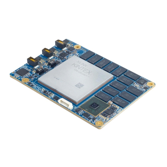
- Page 1 Kintex Ultrascale+ FPGA SOM Hardware User Guide iW-RainboW-G47M Kintex Ultrascale+ FPGA SOM Hardware User Guide REL0.1 iWave Systems Technologies Pvt. Ltd. Page 1 of 95...
- Page 2 (or authorized to receive for the recipient), you are hereby notified that any disclosure, copying distribution or use of any of the information contained within this document is STRICTLY PROHIBITED. Thank you. “iWave Systems Tech. Pvt. Ltd.”...
- Page 3 No warranty of accuracy is given concerning the contents of the information contained in this publication. To the extent permitted by law no liability (including liability to any person by reason of negligence) will be accepted by iWave Systems, its subsidiaries or employees for any direct or indirect loss or damage caused by omissions from or inaccuracies in this document.
-
Page 4: Table Of Contents
Other On SOM Features ..........................25 2.6.1 TPM Module ............................25 2.6.2 Temperature Sensor ..........................26 Board to Board Connector1 ........................27 2.7.1 LS1021A Interfaces ..........................31 USB3.0................................31 2.7.1.1 REL0.1 iWave Systems Technologies Pvt. Ltd. Page 4 of 95... - Page 5 3.2.2 RoHS2 Compliance ..........................88 3.2.3 Electrostatic Discharge ........................88 3.2.4 Heat Sink ............................... 89 Mechanical Characteristics ........................90 3.3.1 Kintex Ultrascale+ FPGA SOM Mechanical Dimensions ............... 90 ORDERING INFORMATION ........................93 REL0.1 iWave Systems Technologies Pvt. Ltd. Page 5 of 95...
- Page 6 Kintex Ultrascale+ FPGA SOM Hardware User Guide APPENDIX ..............................94 Kintex Ultrascale+ FPGA SOM Development Platform ................ 94 REL0.1 iWave Systems Technologies Pvt. Ltd. Page 6 of 95...
- Page 7 Table 7: LS1021A IOMUX on Kintex Ultrascale+ FPGA SOM ......................77 Table 8: Power Input Requirement ............................... 85 Table 9: Power Sequence Timing ..............................86 Table 10: Temperature Specification ............................88 Table 11: Orderable Product Part Numbers ..........................93 REL0.1 iWave Systems Technologies Pvt. Ltd. Page 7 of 95...
-
Page 8: Introduction
This document is the Hardware User Guide for the Kintex Ultrascale+ FPGA System on Module based on the Xilinx Kintex Ultrascale+ FPGA (KU19P). This board is fully supported by iWave Systems Technologies Pvt. Ltd. This Guide provides detailed information on the overall design and usage of the Kintex Ultrascale+ FPGA System on Module from a Hardware Systems perspective. -
Page 9: Terminology Description
Kintex Ultrascale+ FPGA Technical Reference Manual • Kintex Ultrascale+ FPGA Device Overview • Kintex Ultrascale+ FPGAs Data Sheet: DC and AC Switching Characteristics • QorIQ LS1021A Reference Manual • QorIQ LS1021A Data Sheet REL0.1 iWave Systems Technologies Pvt. Ltd. Page 9 of 95... -
Page 10: Architecture And Design
(512KB) I2C2 Temperature Sensor TPM 2.0 JTAG CPU_JTAG Power Power to Dual Arm® Cortex®-A7 CPU Regulators Peripherals Compatible FPGAs: VU9P, VU11P, VU13P Figure 1: Kintex Ultrascale+ FPGA SOM Block Diagram REL0.1 iWave Systems Technologies Pvt. Ltd. Page 10 of 95... -
Page 11: Kintex Ultrascale+ Fpga Som Features
Up to 512 KB coherent L2 cache with single bit error detection and correction, ECC protection PMIC • Dialog’s DA9062 PMIC (with RTC) Memory • 2GB DDR4 SDRAM (32bit) with 4-bit ECC (Expandable) • 256MB NOR Flash (16bit) • 4MB MRAM (16bit) • 512KB SRAM REL0.1 iWave Systems Technologies Pvt. Ltd. Page 11 of 95... - Page 12 Board to Board Connector2 Interfaces (240pin) From LS1021a • Gigabit Ethernet x 1 Port (through On-SOM Gigabit Ethernet PHY) • USB2.0 x 1 Port • Debug UART x 1 Port REL0.1 iWave Systems Technologies Pvt. Ltd. Page 12 of 95...
- Page 13 • Power Supply : 5V (from Board-to-Board Connector2) • Form Factor : 110mm x 75mm In Board-to-Board Connector3, by default one GTY transceiver link is connected with on-SOM PCIe transceiver. REL0.1 iWave Systems Technologies Pvt. Ltd. Page 13 of 95...
-
Page 14: Kintex Ultrascale+ Fpga
PLLs of the same Bank. HDGC pins are from HD I/O banks and have direct access only to the global clock buffers. Also, Kintex Ultrascale+ FPGA supports high speed GTY transceivers. REL0.1 iWave Systems Technologies Pvt. Ltd. Page 14 of 95... -
Page 15: Fpga Power
Important Note: Every Power Off and On, The DA9062 PMIC work as initial OTP Setting 2.3.1.2 FPGA Reset The Kintex Ultrascale+ FPGA SOM uses PMIC’s Reset output (nRESET) for FPGA Power On Reset and connected to AL28 pin (IO_L24N_T3U_N11_DOUT_CSO_B_65) of FPGA. REL0.1 iWave Systems Technologies Pvt. Ltd. Page 15 of 95... -
Page 16: Fpga Reference Clock
FPGA Bank92 HDGC Global clock pin. IO_L7N_HDGC_AD5 AN21 N_92 100MHz MGTREFCLK0P_228 AH11 1.8V, LVDS Bank228 PCIe Reference Clock0. MGTREFCLK0N_228 AH10 125MHz IO_L24P_T3U_N10_ AL27 1.8V, LVCMOS External Master Clock EMCCLK_65 REL0.1 iWave Systems Technologies Pvt. Ltd. Page 16 of 95... -
Page 17: Fpga Configuration & Status
The Kintex Ultrascale+ FPGA SOM supports three dedicated input and output configuration pins. By default, Weak pre - reconfiguration I/O pull-up resistors disabled for PUDC_B pin, Standard FPGA power-on delay time for POR_OVERRIDE pin is connected to Ground through 4.7K. REL0.1 iWave Systems Technologies Pvt. Ltd. Page 17 of 95... -
Page 18: Fpga Mode Configuration
VP_VN dedicated input. The external auxiliary inputs can be routed through any IO Bank. The ADC voltage reference is selectable between an internal reference and the external pins VREFP and VREFN. In Kintex Ultrascale+ FPGA SOM, 1.25V external voltage reference is supported. REL0.1 iWave Systems Technologies Pvt. Ltd. Page 18 of 95... -
Page 19: Fpga Memory
Bank71 J26 & H26 dedicated clock input pins through AC Coupling capacitors. Note: Kintex Ultrascale+ FPGA SOM with -2 & -3 speed grade FPGA can support up to 2666Mbps data rate for FPGA DDR4. REL0.1 iWave Systems Technologies Pvt. Ltd. Page 19 of 95... -
Page 20: Layerscape Processor
NOR Flash. On POR, Pre-Boot Loader (PBL) will fetch RCW configuration and PBL commands from NOR flash (chosen by rcw_src selection pins). Then executes u-boot from NOR flash. REL0.1 iWave Systems Technologies Pvt. Ltd. Page 20 of 95... -
Page 21: Ls1021A Pmic
(Optional) SD1_REF_CLK1_ 100MHz SD1_REF_CLK2_ AC16 1.8V, SerDes PLL 2 Reference Clock LVDS (Optional) SD1_REF_CLK2_ AB16 100MHz DDRCLK 1.8V, DDR controller complex clock. LVCMOS (Optional) 66.66MHz SYSCLK 1.8V, System Clock LVCMOS REL0.1 iWave Systems Technologies Pvt. Ltd. Page 21 of 95... -
Page 22: Processor Memory
The Kintex Ultrascale+ FPGA SOM supports 512KB SPI Serial SRAM memory for storage purpose of LS1021A Processor. This SRAM memory is connected to the SPI2 lane of LS1021A and operates at 1.8V Voltage level. REL0.1 iWave Systems Technologies Pvt. Ltd. Page 22 of 95... -
Page 23: Fpga To Cpu Interfaces
Pin No Name Termination LS_EC3_TXCLK_PL_BC EC3_GTX_CLK/GPI IO_L6N_T0U_N BC27 O, 1.8V Transmit Clock Out 27_L6N_65 O4_01/EC2_TX_ER/ 11_AD6N_A21_ FTM3_CH0/EC3_TX _CLK LS_EC3_TXD0_PL_BC2 EC3_TXD0/GPIO3_ IO_L6P_T0U_N1 BC26 O, 1.8V Transmit Data 6_L6P_65 31/TSEC_1588_PUL 0_AD6P_A20_6 SE_OUT2/FTM3_C REL0.1 iWave Systems Technologies Pvt. Ltd. Page 23 of 95... - Page 24 F28_L1P_65 _08/TSEC_1588_TR _DBC_RS0_65 IG_IN1/FTM3_QD_ LS_EC3_GTXCLK125_P EC3_GTX_CLK125/ IO_L23P_T3U_N AM27 I, 1.8V RGMII TX Reference L_AM27_L23P_65 GPIO4_02/EC2_CO 8_I2C_SCLK_65 Clock L/USB2_DRVVBUS/ EC3_RX_ER * Signal directions mentioned in table are based on LS1021A chip. REL0.1 iWave Systems Technologies Pvt. Ltd. Page 24 of 95...
-
Page 25: Uart
The Kintex Ultrascale+ FPGA SOM supports Trusted Platform Module (TPM) 2.0 Module through LS1021A Processor. The TPM technology is designed to provide hardware-based, security-related functions. A TPM chip is a secure crypto-processor that is REL0.1 iWave Systems Technologies Pvt. Ltd. Page 25 of 95... -
Page 26: Temperature Sensor
Channel 1 connected to the thermal diode pins in the LS1021A processor. And the Channel 2 is connected to the on-chip thermal diode pins of the KU19P SoC. REL0.1 iWave Systems Technologies Pvt. Ltd. Page 26 of 95... -
Page 27: Board To Board Connector1
SOM as shown below. Number of Pins - 240 Connector Part Number - QTH-120-01-L-D-A from Samtec Mating Connector - QSH-120-01-L-D-A from Samtec Staking Height - 5mm Figure 5: Board to Board Connector1 REL0.1 iWave Systems Technologies Pvt. Ltd. Page 27 of 95... -
Page 28: Table 3: Board To Board Connector1 Pinout
PL_AV24_LVDS92_L2P LS_GPIO3_18(EC2_TXD0) PL_AW24_LVDS92_L2N LS_GPIO3_17(EC2_TXD1) PL_AL24_LVDS92_L10P LS_GPIO3_24(EC2_RXD1) PL_AM24_LVDS92_L10N LS_GPIO4_09(TDMA_RXD) GTYTXP2_225 LS_GPIO3_19(EC2_TXEN) GTYTXN2_225 PL_AP24_LVDS92_L9N GTYTXP3_225 PL_AN24_LVDS92_L9P GTYTXN3_225 PL_AR22_LVDS92_L4P PL_AT22_LVDS92_L4N GTYRXN3_225 PL_AV22_LVDS92_L3N GTYRXP3_225 GTYRXN2_225 GTYRXP2_225 LS_SD1_TX2_P GTREFCLK1P_225 LS_SD1_TX2_N GTREFCLK1N_225 PL_AL21_LVDS92_L12P PL_AM21_LVDS92_L12N SD1_REFCLKN SD1_REFCLKP REL0.1 iWave Systems Technologies Pvt. Ltd. Page 28 of 95... - Page 29 GTYTXP0_226 GTREFCLK0P_226 GTYTXN0_226 GTREFCLK0N_226 GTYTXP1_226 GTYTXN1_226 GTYRXN1_226 GTYRXP1_226 GTYRXN0_226 PL_AV28_LVDS65_L14N_A05_D21_GC GTYRXP0_226 PL_AV27_LVDS65_L14P_A04_D20_GC GTYTXP2_226 PL_AV26_LVDS65_L13P_A06_D22_GC GTYTXN2_226 PL_AW26_LVDS65_L13N_A07_D23_GC GTYTXP3_226 PL_AW28_LVDS65_L12P_A08_D24_GC GTYTXN3_226 PL_AY28_LVDS65_L12N_A09_D25_GC GTYRXN3_226 GTYRXP3_226 GTYRXN2_226 PL_AY27_LVDS65_L11N_A11_D27_GC GTYRXP2_226 PL_AY26_LVDS65_L11P_A10_D26_GC LS_USB1_TX_P GTREFCLK1P_226 LS_USB1_TX_M GTREFCLK1N_226 REL0.1 iWave Systems Technologies Pvt. Ltd. Page 29 of 95...
- Page 30 PL_AN27_LVDS65_L23N_PERSTN1_SDA CLK_GEN_IN_P LS_USB1_RX_M LS_USB1_RX_P GTYTXP0_124 GTREFCLK0P_124 GTYTXN0_124 GTREFCLK0N_124 GTYTXP1_124 PL_AM14_LVDS67_L24N GTYTXN1_124 PL_AL14_LVDS67_L24P PL_AT13_T3U_N12_67 GTYRXN1_124 PL_AT14_T2U_N12_67 GTYRXP1_124 PL_BB16_T1U_N12_67 GTYRXN0_124 GTYRXP0_124 GTYTXP2_124 GTREFCLK1P_124 GTYTXN2_124 GTREFCLK1N_124 GTYTXP3_124 GTYTXN3_124 GTYRXN3_124 GTYRXP3_124 SOMPWR_EN GTYRXN2_124 GTYRXP2_124 REL0.1 iWave Systems Technologies Pvt. Ltd. Page 30 of 95...
-
Page 31: Ls1021A Interfaces
2.7.1.3 GPIOs From LS1021A The Kintex Ultrascale+ FPGA SOM supports 6 GPIOs from LS1021A Layerscape Processor in board-to-board connector1 For more details on GPIOs pinouts on Board-to-Board Connector2, refer the below table. REL0.1 iWave Systems Technologies Pvt. Ltd. Page 31 of 95... -
Page 32: Fpga Interfaces
Speed Grade (min) (max) -1L Speed Grade 0.5Gbps 12.5 Gbps -1 Speed Grade 0.5 Gbps 25.785 Gbps -2 Speed Grade 0.5 Gbps 28.21 Gbps -3 Speed Grade 0.5 Gbps 32.75 Gbps REL0.1 iWave Systems Technologies Pvt. Ltd. Page 32 of 95... - Page 33 GTY Bank225 channel3 High speed differential transmitter positive. GTYTXN3_225 MGTYTXN3_225 O, DIFF GTY Bank225 channel3 High speed differential transmitter negative. GTYRXN3_225 MGTYRXN3_225 I, DIFF GTY Bank225 channel3 High speed differential receiver negative. REL0.1 iWave Systems Technologies Pvt. Ltd. Page 33 of 95...
- Page 34 GTY Bank226 channel3 High speed differential transmitter positive. GTYTXN3_226 MGTYTXN3_226 O, DIFF GTY Bank226 channel3 High speed differential transmitter negative. GTYRXN3_226 MGTYRXN3_226 I, DIFF GTY Bank226 channel3 High speed differential receiver negative. REL0.1 iWave Systems Technologies Pvt. Ltd. Page 34 of 95...
-
Page 35: Fpga Ios - Hd Bank92
Signal Name Name Bank Termination* PL_AV24_LVDS9 IO_L2P_AD10P AV24 IO, 3.3V Bank92 IO2 differential positive. 2_L2P Same pin can be configured as SYSMON differential analog input10 positive or Single ended I/O. REL0.1 iWave Systems Technologies Pvt. Ltd. Page 35 of 95... - Page 36 Single ended I/O. PL_AL22_LVDS9 IO_L11P_AD1P AL22 IO, 3.3V Bank92 IO11 differential positive. 2_L11P Same pin can be configured as PLSYSMON differential analog input1 positive or Single ended I/O. REL0.1 iWave Systems Technologies Pvt. Ltd. Page 36 of 95...
- Page 37 Single ended I/O. PL_AT22_LVDS9 IO_L4N_AD8N_ AT22 IO, 3.3V Bank92 IO4 differential negative. 2_L4N Same pin can be configured as PLSYSMON differential analog input8 negative or Single ended I/O. REL0.1 iWave Systems Technologies Pvt. Ltd. Page 37 of 95...
- Page 38 126, 130, 132, 142 and 144 are HDGC Global Clock Input capable pins of Bank65. For more details on HD Bank65 & 67 pinouts on Board-to-Board Connector1, refer the below table. REL0.1 iWave Systems Technologies Pvt. Ltd. Page 38 of 95...
- Page 39 I/O. PL_AW28_LVDS IO_L12P_T1U_ AW28 IO, 1.8V Bank65 IO12 differential positive. 65_L12P_A08_D N10_GC_A08_D Same pin can be configured as GC Global 24_GC 24_65 Clock Input differential positive or Single ended I/O. REL0.1 iWave Systems Technologies Pvt. Ltd. Page 39 of 95...
-
Page 40: Power Control Input
205, 215, 221, 227, 233, 239, 2, 8, 20, 26, 36, 54, 60, 62, 68, 80, 86, 96, 102, 114, 120, 122, 140, 146, 156, 162, 174, 180, 182, 188, 200, 206, 216, 222, 234, 240 REL0.1 iWave Systems Technologies Pvt. Ltd. Page 40 of 95... -
Page 41: Board To Board Connector2
SOM as shown below. Number of Pins - 240 Connector Part Number - QTH-120-01-L-D-A from Samtec Mating Connector - QSH-120-01-L-D-A from Samtec Staking Height - 5mm Figure 6: Board to Board Connector2 REL0.1 iWave Systems Technologies Pvt. Ltd. Page 41 of 95... -
Page 42: Table 4: Board To Board Connector2 Pinout
LS_GPIO4_16(TDMB_TXD) GPHY_CTXRXM LS_IIC1_SDA GPHY_CTXRXP LS_IIC1_SCL LS_LPUART3_SOUT GPHY_BTXRXM LS_LPUART3_SIN GPHY_BTXRXP LS_UART1_SOUT LS_UART1_SIN GPHY_ATXRXM GPHY_LINK_LED2 GPHY_ATXRXP GPHY_ACTIVITY_LED1 LS_GPIO3_15(EC2_TXD3) LS_GPIO4_19(CLK09) PL_AN28_LVDS65_L20P_D08 LS_GPIO4_14(TDMB_RXD) LS_GPIO4_25(SDHC_DAT6) LS_GPIO4_15(TDMB_RSYNC) B2B_RTC LS_GPIO4_18(TDMB_RQ) LS_IIC2_SCL LS_GPIO4_12(TDMA_TSYNC) LS_GPIO4_24(SDHC_DAT5) PL_AV16_LVDS67_L18N B2B2_SCL PL_AU16_LVDS67_L18P B2B2_SDA REL0.1 iWave Systems Technologies Pvt. Ltd. Page 42 of 95... - Page 43 PL_AL20_LVDS66_L24P PL_AL17_LVDS66_L22P_DBC PL_AM20_LVDS66_L24N PL_AM17_LVDS66_L22N_DBC PL_AN19_LVDS66_L20P PL_AM16_LVDS66_L21P PL_AP19_LVDS66_L20N PL_AN16_LVDS66_L21N PL_BD15_LVDS67_L5P PL_AL19_LVDS66_L23P PL_BD14_LVDS67_L5N PL_AM19_LVDS66_L23N PL_BF15_LVDS67_L2N PL_AP18_LVDS66_L17P PL_BE15_LVDS67_L2P PL_AR18_LVDS66_L17N PL_AP20_LVDS66_L18P PL_BD18_LVDS66_L3P PL_AR20_LVDS66_L18N PL_BE18_LVDS66_L3N PL_AY18_LVDS66_L8P PL_BE17_LVDS66_L1P_DBC PL_BA18_LVDS66_L8N PL_BF17_LVDS66_L1N_DBC PL_AV21_LVDS66_L10P_QBC PL_AR17_LVDS66_L16P_QBC PL_AW21_LVDS66_L10N_QBC PL_AT17_LVDS66_L16N_QBC PL_BC19_LVDS66_L4P_DBC PL_BF18_LVDS66_L2N REL0.1 iWave Systems Technologies Pvt. Ltd. Page 43 of 95...
- Page 44 B2B-2 Pin Signal Name PL_BD19_LVDS66_L4N_DBC PL_BF19_LVDS66_L2P PL_BB19_LVDS66_L6P PL_AT18_LVDS66_L15P PL_BC18_LVDS66_L6N PL_AU17_LVDS66_L15N PL_AT20_LVDS66_L14P_GC PL_AV19_LVDS66_L12P_GC PL_AU20_LVDS66_L14N_GC PL_AW19_LVDS66_L12N_GC PL_AT19_LVDS66_L13P_GC PL_AV18_LVDS66_L11P_GC PL_AU19_LVDS66_L13N_GC PL_AW18_LVDS66_L11N_GC PL_BC17_LVDS66_L5N PL_AY17_LVDS66_L7P_QBC PL_BB17_LVDS66_L5P PL_BA17_LVDS66_L7N_QBC LS_SD1_RX3_P LS_SD1_RX3_N SD1_TX3_P SD1_TX3_N LS_SD1_RX1_P LS_SD1_RX1_N SD1_TX1_P SD1_TX1_N REL0.1 iWave Systems Technologies Pvt. Ltd. Page 44 of 95...
-
Page 45: Ls1021A Interfaces
Gigabit Ethernet differential pair 3 positive. GPHY_CTXRXM IO, GBE Gigabit Ethernet differential pair 3 negative. GPHY_DTXRXP IO, GBE Gigabit Ethernet differential pair 4 positive. GPHY_DTXRXM IO, GBE Gigabit Ethernet differential pair 4 negative. REL0.1 iWave Systems Technologies Pvt. Ltd. Page 45 of 95... -
Page 46: Usb2.0 Interface
B2B Connector2 LS1021A Pin LS1021A Signal Type/ Description Pin No Signal Name Name Pin No Termination LS_UART1_SOUT UART1_SOUT/G Debug UART Transmit data PIO1_15 LS_UART1_SIN UART1_SIN/GPI Debug UART Receive data O1_17 REL0.1 iWave Systems Technologies Pvt. Ltd. Page 46 of 95... -
Page 47: Data Uart Interface
Signal Name Name Pin No Termination LS_IIC1_SDA IIC1_SDA I2C1 Serial Data LS_IIC1_SCL IIC1_SCL I2C1 Serial Clock LS_IIC2_SCL IIC2_SCL/GPIO4 I2C2 Serial Clock _27/SDHC_CD_ B/SPI2_PCS3 LS_IIC2_SDA IIC2_SDA/GPIO4 I2C2 Serial Data _28/SDHC_WP/ SPI2_PCS4 REL0.1 iWave Systems Technologies Pvt. Ltd. Page 47 of 95... -
Page 48: Jtag Interface
The Kintex Ultrascale+ FPGA SOM supports 2 highspeed SerDes lanes through LS1021A Layerscape Processor in board-to-board connector2 For more details on SerDes Interface pinouts on Board-to-Board Connector2, refer the below table. REL0.1 iWave Systems Technologies Pvt. Ltd. Page 48 of 95... -
Page 49: Gpios From Ls1021A
General Purpose I/O TDMB_RQ) XER/SPDIF_EXTCLK/SAI4_RX_BCLK/ from LS1021A FTM4_EXTCLK/2D-ACE_D09 LS_GPIO4_12( TDMA_TSYNC/GPIO4_12/UC1_RTS IO, 1.8V General Purpose I/O TDMA_TSYNC) B_TXEN/SAI3_TX_SYNC/FTM4_CH4 from LS1021A /2D-ACE_D03 LS_GPIO4_26( SDHC_DAT7/GPIO4_26/USB1_PWR IO, 1.8V General Purpose I/O SDHC_DAT7) FAULT/SDHC_DAT123_DIR from LS1021A REL0.1 iWave Systems Technologies Pvt. Ltd. Page 49 of 95... -
Page 50: Fpga Interfaces
Single ended I/O. PL_AP19_LVDS66 IO_L20N_T3L_N3_ AP19 IO, 1.8V Bank66 IO20 differential negative. _L20N AD1N_66 Same pin can be configured as PLSYSMON differential analog input1 negative or Single ended I/O. REL0.1 iWave Systems Technologies Pvt. Ltd. Page 50 of 95... - Page 51 Single ended I/O. PL_BC18_LVDS66 IO_L6N_T0U_N11 BC18 IO, 1.8V Bank66 IO6 differential negative. _L6N _AD6N_66 Same pin can be configured as PLSYSMON differential analog input6 negative or Single ended I/O. REL0.1 iWave Systems Technologies Pvt. Ltd. Page 51 of 95...
- Page 52 Single ended I/O. PL_AY20_LVDS66 IO_L9N_T1L_N5_A AY20 IO, 1.8V Bank66 IO9 differential negative. _L9N D12N_66 Same pin can be configured as PLSYSMON differential analog input12 negative or Single ended I/O. REL0.1 iWave Systems Technologies Pvt. Ltd. Page 52 of 95...
- Page 53 Single ended I/O. PL_BE18_LVDS66 IO_L3N_T0L_N5_A BE18 IO, 1.8V Bank66 IO3 differential negative. _L3N D15N_66 Same pin can be configured as PLSYSMON differential analog input15 negative or Single ended I/O. REL0.1 iWave Systems Technologies Pvt. Ltd. Page 53 of 95...
- Page 54 Single ended I/O. PL_AV18_LVDS6 IO_L11P_T1U_N8 AV18 IO, 1.8V Bank66 IO11 differential positive 6_L11P_GC _GC_66 Same pin can be configured as GC Global Clock Input differential positive or Single ended I/O. REL0.1 iWave Systems Technologies Pvt. Ltd. Page 54 of 95...
-
Page 55: Fpga Ios -Hp Bank67
LVDS IOs, these pins can be used as SE IOs if required. The Board-to-Board Connector2 pins 109, 110, 111, 115, 116, 117, 118 and 110 are GC Global Clock Input capable pins of Bank67. Also, Board to Board Connector2 pins 75, 77, 78, 80, REL0.1 iWave Systems Technologies Pvt. Ltd. Page 55 of 95... - Page 56 Same pin can be configured as Single ended I/O. PL_BD13_LVDS6 IO_L4P_T0U_N6_ BD13 IO, 1.8V Bank67 IO4 differential positive. 7_L4P_DBC DBC_AD7P_67 Same pin can be configured as PLSYSMON differential analog input7 positive or Single ended I/O. REL0.1 iWave Systems Technologies Pvt. Ltd. Page 56 of 95...
- Page 57 Global Clock differential negative or Single ended I/O. PL_AY15_LVDS67 IO_L9N_T1L_N5_ AY15 IO, 1.8V Bank67 IO9 differential negative. _L9N AD12N_67 Same pin can be configured as PLSYSMON differential analog input12 negative or Single ended I/O. REL0.1 iWave Systems Technologies Pvt. Ltd. Page 57 of 95...
- Page 58 DBC_67 Same pin can be configured as Single ended I/O. PL_BF14_LVDS67 IO_L1P_T0L_N0_ BF14 IO, 1.8V Bank67 IO1 differential positive. _L1P DBC_67 Same pin can be configured as Single ended I/O. REL0.1 iWave Systems Technologies Pvt. Ltd. Page 58 of 95...
- Page 59 Single ended I/O. PL_BB12_LVDS67 IO_L7N_T1L_N1_ BB12 IO, 1.8V Bank67 IO7 differential negative. _L7N_QBC QBC_AD13N_67 Same pin can be configured as PLSYSMON differential analog input13 negative or Single ended I/O. REL0.1 iWave Systems Technologies Pvt. Ltd. Page 59 of 95...
- Page 60 Global Clock differential negative or Single ended I/O. *IO Type of IOs originating from KU19P FPGA is configurable. Hence for exact IO type configuration options, refer Xilinx KU19P FPGA datasheet. REL0.1 iWave Systems Technologies Pvt. Ltd. Page 60 of 95...
-
Page 61: Power & Reset Input
239, 22, 24, 30, 74, 108, 114, 120, 130, 168, 174, 180, 186, 192, 198, 204, 210, 216, 222, 228, 234, VRTC_3V0 I, 3V Power 3V backup coin cell input for RTC. REL0.1 iWave Systems Technologies Pvt. Ltd. Page 61 of 95... -
Page 62: Board To Board Connector3
SOM as shown below. Number of Pins - 240 Connector Part Number - ADM6-60-01.5-L-4-2-A from Samtech Mating Connector - ADF6-60-03.5-L-4-2-A from Samtech Staking Height - 5mm Figure 7: Board to Board Connector3 REL0.1 iWave Systems Technologies Pvt. Ltd. Page 62 of 95... -
Page 63: Table 5: Board To Board Connector3 Pinout
GTYRXP1_230 GTYRXP0_231 GTYTXN1_230 GTYRXP2_228 GTYTXP1_230 GTYRXN2_228 GTYTXN3_230 GTYTXN1_231 GTYTXP3_230 GTYTXP1_231 GTYTXN0_230 GTYRXP1_228 GTYTXP0_230 GTYRXN1_228 GTYTXN2_230 GTREFCLK1N_231 GTYTXP2_230 GTREFCLK1P_231 GTREFCLK0N_230 GTYRXP0_228 GTREFCLK0P_230 GTYRXN0_228 GTREFCLK1N_230 GTREFCLK0P_231 GTREFCLK1P_230 GTREFCLK0N_231 GTYRXN3_229 B2B_GTYTXN3_22 GTYRXP3_229 B2B_GTYTXP3_22 REL0.1 iWave Systems Technologies Pvt. Ltd. Page 63 of 95... - Page 64 GTYTXN1_228 GTYTXN1_229 GTYTXP1_228 GTYTXP0_229 GTYTXN3_231 GTYTXN0_229 GTYTXP3_231 GTREFCLK1P_229 GTYTXN0_228 GTREFCLK1N_229 GTYTXP0_228 GTYRXP1_229 GTYTXN2_231 GTYRXN1_229 GTYTXP2_231 GTREFCLK0P_229 GTREFCLK1N_228 GTREFCLK0N_229 GTREFCLK1P_228 GTYRXP0_229 GTYTXN0_231 GTYRXN0_229 GTYTXP0_231 GTYRXN1_232 GTYRXP1_232 GTYRXN2_232 GTYRXP2_232 GTYRXN3_232 GTYRXP3_232 GTREFCLK0P_232 REL0.1 iWave Systems Technologies Pvt. Ltd. Page 64 of 95...
- Page 65 B2B-3 B2B-3 B2B-3 Signal Name Signal Name Signal Name Signal Name Pin No Pin No Pin No Pin No GTREFCLK0N_232 GTYRXN0_232 GTYRXP0_232 GTYTXP0_232 GTYTXN0_232 GTYTXP2_232 GTYTXN2_232 GTYTXN1_232 GTYTXP1_232 GTYTXP3_232 GTYTXN3_232 REL0.1 iWave Systems Technologies Pvt. Ltd. Page 65 of 95...
-
Page 66: Fpga Interfaces
GTYRXP0_228 MGTYRXP0_228 differential receiver positive. I, DIFF GTY Bank228 channel0 High speed GTYRXN0_228 MGTYRXN0_228 differential receiver negative. B2B_GTYTXN3_ O, DIFF GTY Bank228 channel3 High speed MGTYTXN3_228 228* differential transmitter negative. REL0.1 iWave Systems Technologies Pvt. Ltd. Page 66 of 95... - Page 67 GTY Bank229 channel0 High speed GTYRXP0_229 MGTYRXP0_229 differential receiver positive. I, DIFF GTY Bank229 channel0 High speed GTYRXN0_229 MGTYRXN0_229 differential receiver negative. I, DIFF GTY Bank229 channel3 High speed GTYRXN3_229 MGTYRXN3_229 differential receiver negative. REL0.1 iWave Systems Technologies Pvt. Ltd. Page 67 of 95...
- Page 68 GTY Bank230 channel1 High speed differential reference clock1 negative. GTREFCLK1P_23 MGTREFCLK1P_2 I, DIFF GTY Bank230 channel1 High speed differential reference clock1 positive. I, DIFF GTY Bank230 channel2 High speed GTYRXN2_230 MGTYRXN2_230 differential receiver negative. REL0.1 iWave Systems Technologies Pvt. Ltd. Page 68 of 95...
- Page 69 GTY Bank231 channel0 High speed differential reference clock0 positive. GTREFCLK0N_23 MGTREFCLK0N_ I, DIFF GTY Bank231 channel0 High speed differential reference clock0 negative. I, DIFF GTY Bank231 channel3 High speed GTYRXN3_231 MGTYRXN3_231 differential receiver negative. REL0.1 iWave Systems Technologies Pvt. Ltd. Page 69 of 95...
- Page 70 GTY Bank232 channel1 High speed GTYTXN1_232 MGTYTXN1_232 differential transmitter negative. O, DIFF GTY Bank232 channel1 High speed GTYTXP1_232 MGTYTXP1_232 differential transmitter positive. I, DIFF GTY Bank232 channel1 High speed GTYRXN1_232 MGTYRXN1_232 differential receiver negative. REL0.1 iWave Systems Technologies Pvt. Ltd. Page 70 of 95...
-
Page 71: Power
On-SOM itself. Also, in Board-to-Board Connector3, Ground pins are distributed throughout the connector for better performance. For more details on Power pins on Board-to-Board Connector3, refer the below table. REL0.1 iWave Systems Technologies Pvt. Ltd. Page 71 of 95... - Page 72 D1, D4, D5, D8, D9, D12, D13, D16, D17, D20, D21, D24, D25, D28, D29, D32, D33, D36, D37, D40, D41, D44, D45, D48, D49, D52, D53, D56, D57, D60, REL0.1 iWave Systems Technologies Pvt. Ltd. Page 72 of 95...
-
Page 73: Board To Board Connector4
SOM as shown below. Number of Pins - 80 Connector Part Number - ADM6-20-01.5-L-4-2-A from Samtech Mating Connector - ADF6-20-03.5-L-4-2-A from Samtech Staking Height - 5mm Figure 8: Board to Board Connector4 REL0.1 iWave Systems Technologies Pvt. Ltd. Page 73 of 95... -
Page 74: Table 6: Board To Board Connector4 Pinout
Signal Name Pin No Pin No Pin No Pin No GTREFCLK1N_227 GTYRXN1_227 GTREFCLK1P_227 GTYRXP1_227 GTYRXN3_227 GTYRXP3_227 GTREFCLK0P_227 GTREFCLK0N_227 GTYRXN2_227 GTYRXP2_227 GTYTXP0_227 GTYTXN0_227 GTYTXP3_227 GTYTXN3_227 GTYTXP1_227 GTYTXN1_227 GTYRXN0_227 GTYRXP0_227 GTYTXP2_227 GTYTXN2_227 REL0.1 iWave Systems Technologies Pvt. Ltd. Page 74 of 95... -
Page 75: Fpga Interfaces
GTREFCLK1P_227 AK11 differential reference clock1 positive. I, DIFF GTY Bank227 channel3 High speed GTYRXN3_227 MGTYRXN3_227 differential receiver negative. I, DIFF GTY Bank227 channel3 High speed GTYRXP3_227 MGTYRXP3_227 differential receiver positive. REL0.1 iWave Systems Technologies Pvt. Ltd. Page 75 of 95... -
Page 76: Power
A12, A13, A16, A17, A20, B3, B6, B7, B10, B11, B14, B15, B18, B19, C1, C4, C5, C8, C9, C12, C13, C16, C17, C20, D2, D3, D6, D7, D10, D11, D14, D15, D18, REL0.1 iWave Systems Technologies Pvt. Ltd. Page 76 of 95... -
Page 77: Ls1021A Processor Pin Multiplexing On Board-To-Board Connectors
IFC_CS5_B FTM5_CH1 C_RB3_B/IFC_CS5_B IFC_A27/GPIO2_27/FTM5_EXTCL IFC_A27 GPIO2_27 IFC_CS6_B FTM5_EXTCLK K/IFC_CS6_B IFC_AD00/cfg_gpinput0 IFC_AD00 cfg_gpinput0 IFC_AD01/cfg_gpinput1 IFC_AD01 cfg_gpinput1 IFC_AD02/cfg_gpinput2 IFC_AD02 cfg_gpinput2 IFC_AD03/cfg_gpinput3 IFC_AD03 cfg_gpinput3 IFC_AD04/cfg_gpinput4 IFC_AD04 cfg_gpinput4 IFC_AD05/cfg_gpinput5 IFC_AD05 cfg_gpinput5 IFC_AD06/cfg_gpinput6 IFC_AD06 cfg_gpinput6 REL0.1 iWave Systems Technologies Pvt. Ltd. Page 77 of 95... - Page 78 IFC_CS2_B/GPIO2_11/ IFC_CS2_B GPIO2_11 SPI1_SCK FTM7_CH1 IIC3_SCL SPI1_SCK/FTM7_CH1/ IIC3_SCL IFC_CS3_B /GPIO2_12/ IFC_CS3_B GPIO2_12 IIC3_SDA QSPI_DIO_B3 FTM7_EXTCLK QSPI_DIO_B3/IIC3_SDA/ FTM7_EXTCLK IFC_NDDDR_CLK IFC_NDDDR_CL IFC_NDDQS IFC_NDDQS IFC_OE_B/cfg_eng_use1 IFC_OE_B cfg_eng_use1 IFC_PAR0/GPIO2_13/QSPI_DIO_B IFC_PAR0 GPIO2_13 QSPI_DIO_B0 FTM6_CH0 0/FTM6_CH0 REL0.1 iWave Systems Technologies Pvt. Ltd. Page 78 of 95...
- Page 79 SAI2_RX_DATA FTM1_CH6 CAN1_RX/SAI2_RX_DATA/ FTM1_CH6 EC1_RXD3/GPIO3_09/ EC1_RXD3 GPIO3_09 CAN2_RX SAI1_RX_DATA FTM1_CH4 CAN2_RX/SAI1_RX_DATA/ FTM1_CH4 EC1_TX_EN/GPIO3_06/ EC1_TX_EN GPIO3_06 SAI1_TX_BCLK FTM1_FAULT SAI1_TX_BCLK/FTM1_FAULT EC1_TXD0/GPIO3_05/ EC1_TXD0 GPIO3_05 SAI2_TX_SYNC FTM1_CH2 SAI2_TX_SYNC/FTM1_CH2 EC1_TXD1/GPIO3_04/ EC1_TXD1 GPIO3_04 SAI1_TX_SYNC FTM1_CH3 SAI1_TX_SYNC/FTM1_CH3 REL0.1 iWave Systems Technologies Pvt. Ltd. Page 79 of 95...
- Page 80 GPIO3_31 TSEC_1588_PUL FTM3_CH4 TSEC_1588_PULSE_OUT2/ SE_OUT2 FTM3_CH4 EC3_TXD1/GPIO3_30/ EC3_TXD1 GPIO3_30 TSEC_1588_CLK FTM3_CH5 TSEC_1588_CLK_OUT/ _OUT FTM3_CH5 EC3_TXD2/GPIO3_29/ EC3_TXD2 GPIO3_29 TSEC_1588_ALA FTM3_CH6 TSEC_1588_ALARM_OUT1/ RM_OUT1 FTM3_CH6 EC3_TXD3/GPIO3_28/ EC3_TXD3 GPIO3_28 TSEC_1588_ALA FTM3_CH7 TSEC_1588_ALARM_OUT2/ RM_OUT2 FTM3_CH7 REL0.1 iWave Systems Technologies Pvt. Ltd. Page 80 of 95...
- Page 81 SPI2_PCS1 LPUART1_SIN/SPI2_PCS1 UART2_SOUT/GPIO1_16/ UART2_SOUT GPIO1_16 LPUART1_SOU SPI2_PCS0 SPI2_PCS0/LPUART1_SOUT EC2_GTX_CLK/GPIO3_20/ EC2_GTX_CLK GPIO3_20 USB2_CLK EC2_TX_CLK FTM2_EXTCLK EC2_TX_CLK/USB2_CLK/ FTM2_EXTCLK EC2_GTX_CLK125GPIO3_21/EC2_ EC2_GTX_CLK12 GPIO3_21 USB2_PWRFAUL EC2_RX_ER GPIO RX_ER/ USB2_PWRFAULT EC2_RX_CLK/GPIO3_26/ EC2_RX_CLK GPIO3_26 USB2_DIR FTM2_QD_PH USB2_DIR/FTM2_QD_PHA REL0.1 iWave Systems Technologies Pvt. Ltd. Page 81 of 95...
- Page 82 Board to Board Connectorr1 Interfaces from LS1021A EC2_RXD1/GPIO3_24/ EC2_RXD1 GPIO3_24 USB2_D1 FTM2_CH1 USB2_D1/FTM2_CH1 EC2_RXD3/GPIO3_22/ EC2_RXD3 GPIO3_22 CAN4_RX USB2_D3 FTM2_CH4 CAN4_RX/USB2_D3/ FTM2_CH4 GPIO EC2_TX_EN/GPIO3_19/ EC2_TX_EN GPIO3_19 USB2_STP FTM2_FAULT USB2_STP/FTM2_FAULT EC2_TXD0/GPIO3_18/ EC2_TXD0 GPIO3_18 USB2_D4 FTM2_CH2 USB2_D4/FTM2_CH2 REL0.1 iWave Systems Technologies Pvt. Ltd. Page 82 of 95...
- Page 83 CAN3_TX/USB2_D6/ FTM2_CH7 EC2_TXD3/GPIO3_15/ EC2_TXD3 GPIO3_15 CAN4_TX USB2_D7 FTM2_CH5 CAN4_TX/USB2_D7/ FTM2_CH5 SDHC_DAT5/GPIO4_24/ SDHC_DAT5 GPIO4_24 SDHC_CMD_DIR GPIO SDHC_CMD_DIR SDHC_DAT6/GPIO4_25/ SDHC_DAT6 GPIO4_25 USB1_DRVVB SDHC_DAT0_DI USB1_DRVVBUS/ SDHC_DAT0_DIR SDHC_DAT7/GPIO4_26/ SDHC_DAT7 GPIO4_26 USB1_PWRFA SDHC_DAT123_ USB1_PWRFAULT/ SDHC_DAT123_DIR REL0.1 iWave Systems Technologies Pvt. Ltd. Page 83 of 95...
- Page 84 UC3_CTSB_RXD SAI4_TX_BCLK 2D-ACE_D06 FTM4_CH1 UC3_CTSB_RXDV/ SPDIF_PLOCK/ SAI4_TX_BCLK/ FTM4_CH1/2D-ACE_D06 TDMB_RXD/GPIO4_14/ TDMB_RXD GPIO4_14 SPDIF_IN UC3_RXD7 SAI4_RX_DATA 2D-ACE_D05 FTM4_CH2 UC3_RXD7/SPDIF_IN/ SAI4_RX_DATA/ FTM4_CH2/2D-ACE_D05 TDMB_TXD/GPIO4_16/ TDMB_TXD GPIO4_16 SPDIF_OUT UC3_TXD7 SAI4_TX_DATA 2D-ACE_D07 FTM4_CH0 UC3_TXD7/SPDIF_OUT/ SAI4_TX_DATA/ FTM4_CH0/2D-ACE_D07 REL0.1 iWave Systems Technologies Pvt. Ltd. Page 84 of 95...
-
Page 85: Technical Specification
² Kintex Ultrascale+ FPGA (KU19P) SOM uses this voltage as backup power source to PMIC RTC when VCC_5V is off. This is an optional power and required only if RTC functionality is used. REL0.1 iWave Systems Technologies Pvt. Ltd. Page 85 of 95... -
Page 86: Power Input Sequencing
VCC_5V input power to other all the powers are getting stable around 50ms in SOM, Make sure that from the carrier board IOs shall not driving before all the SOM powers are stable. REL0.1 iWave Systems Technologies Pvt. Ltd. Page 86 of 95... -
Page 87: Power Consumption
Kintex Ultrascale+ FPGA (KU19P) SOM Hardware User Guide 3.1.3 Power Consumption REL0.1 iWave Systems Technologies Pvt. Ltd. Page 87 of 95... -
Page 88: Environmental Characteristics
3.2.3 Electrostatic Discharge iWave’s Kintex Ultrascale+ FPGA (KU19P) SOM is sensitive to electro static discharge and so high voltages caused by static electricity could damage some of the devices on board. It is packed with necessary protection while shipping. -
Page 89: Heat Sink
To dissipate the heat, appropriate thermal management technique Heat sink must be used. Always remember that, if you use more effective thermal solution, you will get more performance out of the CPU. Figure 10: Heat Sink REL0.1 iWave Systems Technologies Pvt. Ltd. Page 89 of 95... -
Page 90: Mechanical Characteristics
Kintex Ultrascale+ FPGA (KU19P) SOM PCB size is 110mm x 75mm x 2.64mm and weight is 125g. SOM mechanical dimension is shown below. Figure 11: Mechanical dimension of Kintex Ultrascale+ FPGA SOM - Top View REL0.1 iWave Systems Technologies Pvt. Ltd. Page 90 of 95... -
Page 91: Figure 12: Mechanical Dimension Of Kintex Ultrascale+ Fpga Som - Bottom View
L1, L2, L3 (6mm) and bottom side maximum height component is Board to Board connector 1 & 2 (4.27mm) followed by Board-to-Board connector 3(4.02mm). Please refer the below figure which gives height details of the Kintex Ultrascale+ FPGA SOM. REL0.1 iWave Systems Technologies Pvt. Ltd. Page 91 of 95... -
Page 92: Figure 13: Mechanical Dimension Of Kintex Ultrascale+ Fpga Som - Side View
Kintex Ultrascale+ FPGA (KU19P) SOM Hardware User Guide Figure 13: Mechanical dimension of Kintex Ultrascale+ FPGA SOM - Side View REL0.1 iWave Systems Technologies Pvt. Ltd. Page 92 of 95... -
Page 93: Ordering Information
The below table provides the standard orderable part numbers for different Kintex Ultrascale+ FPGA (KU19P) SOM variations. Please contact iWave for orderable part number of higher RAM memory size or Flash memory size SOM configurations. Also, if the desired part number is not listed in below table or if any custom configuration part number is required, please contact iWave. -
Page 94: Figure 14 Kintex Ultrascale+ Fpga (Ku19P) Development Platform
Systems supports iW-RainboW-G47D– Kintex Ultrascale+ FPGA SOM Development Platform which is targeted for quick validation of Kintex Ultrascale+ FPGA (KU19P) based SOM. iWave's Kintex Ultrascale+ FPGA Development Board incorporates Kintex Ultrascale+ FPGA (KU19P) SOM and High-performance Carrier board with complete BSP support. -
Page 95: Iwave Systems Technologies Pvt. Ltd
Kintex Ultrascale+ FPGA (KU19P) SOM Hardware User Guide REL0.1 iWave Systems Technologies Pvt. Ltd. Page 95 of 95...
Need help?
Do you have a question about the iW-RainboW-G47M and is the answer not in the manual?
Questions and answers