
Subscribe to Our Youtube Channel
Related Manuals for Svantek SV 104BIS


Summary of Contents for Svantek SV 104BIS
- Page 1 USER MANUAL SV 104BIS ACOUSTIC DOSIMETER Copyright © 2022 SVANTEK. Warsaw, 2022-07-27 Rev. 1.02 All rights reserved.
- Page 2 Svantek provides this document “as is”, without warranty of any kind, either expressed or implied, including, but not limited to, its particular purpose. Svantek reserves the right to make improvements and/or changes to this manual, or to the products and/or the programs described in this manual, at any time.
-
Page 3: General Warnings, Safety Clauses, And Standard Information
6.3.9.4 and 7.8). “The Bluetooth ® word mark and logos are registered trademarks owned by Bluetooth SIG, Inc. and any use of such marks by SVANTEK is under license. Other trademarks and trade names are those of their respective owners. -
Page 4: Hazardous Area Installations Specific Information
5. Before entering hazardous zone check if there is no display shipping protection foil in place, which is used on new products being sent to protect from accidental scratches. See Chapter 4.2. 6. The SV 104BIS instrument shall not be used in areas where a layer of coal dust may be deposited on the enclosure. -
Page 5: Special Precautions When Using And Charging Lithium Batteries
SPECIAL PRECAUTIONS WHEN USING AND CHARGING LITHIUM BATTERIES SV 104BIS instrument contains extremely high energy density lithium-ion cell. Use special caution when working with lithium-ion cells. They are very sensitive to charging conditions and may explode or burn if mishandled. -
Page 6: Environmental Protection Marking Of The Unit
SV 104BIS User Manual ENVIRONMENTAL PROTECTION MARKING OF THE UNIT Marking on the Unit Explanation IP65 Dust-tight. Protected against water jets ATTENTION, CONSULT ACCOMPANYING DOCUMENTS Do not throw into standard municipal waste containers. The user is obliged to deliver used equipment to the manufacturer or to the... -
Page 7: Index
SV 104BIS User Manual INDEX 1/1-octave analyser · 28 General settings · 64 1/1-octave settings · 64 1/3-octave analyser · 29 1/3-octave settings · 64 Icons · 23 Instrument control · 24, 48 Instrument status view · 31 Accessories · 17 Interfaces ·... - Page 8 SV 104BIS User Manual Reset · 44, 45 Time-history settings · 62 Results list view · 28 Timer · 31, 43, 67 Results view · 50 Transportation · 89 Risk mitigation · 90 Troubleshooting · 89 Running SPL view · 27 Turning off ·...
-
Page 9: Table Of Contents
ENVIRONMENTAL PROTECTION MARKING OF THE UNIT INDEX INTRODUCTION Sound pressure Dosimetry Standards Applications Measurement procedures KIT COMPONENTS SV 104BIS dosimeter short form specification Accessories included Accessories available Firmware options available GETTING STARTED System description Input / output interfaces Windscreen Mounting clips... - Page 10 SV 104BIS User Manual RUNNING AND OPERATING BASIC PROCEDURES Charging SV 104BIS Before you turn the instrument on Turning on/off Battery check Reviewing unit label Measurement setup - basic configuration Calibration Voice comments recording Before and after measurement run 4.10 Starting and stopping measurement run 4.11...
- Page 11 SV 104BIS User Manual 6.3.9.3 Keyboard security 6.3.9.4 Auxiliary settings 6.3.10 Auto-Run settings (timer, pauses) 6.3.11 Recording options 6.3.11.1 Wave recording configuration Working with data files 6.4.1 Downloading files 6.4.2 Data Browser 6.4.2.1 File Manager 6.4.2.2 File details 6.4.2.3 File preview 6.4.2.4...
- Page 12 Specification of SV 104BIS as DOSIMETER C.1.1 Specification of SV 104BIS as dosimeter in standard configuration Specification of the SV 104BIS as 1/1 and 1/3 OCTAVE ANALYSER Frequency characteristics of the implemented digital filters General specification of the SV 104BIS...
-
Page 13: Introduction
“Never before has a noise dosimeter been so accomplished yet so affordable, making your measurements more accurate and reliable than ever before”. To get started quickly with SV 104BIS, the first part of the manual describes basic noise dosimetry information followed by a guide to setting up the dosimeter and running measurements. -
Page 14: Sound Pressure
SV 104BIS User Manual OUND PRESSURE The human ear responds to audible sound pressure levels in the range from 20 μPa (hearing threshold) to 20 Pa (pain threshold), resulting in the enormous scale 1:1,000,000. Since using such a large arithmetic scale is not practical, a logarithmic scale in decibels (dB) was introduced which is also in agreement with physiological and psychological hearing sensations. -
Page 15: Applications
One of the most desirable SV 104BIS feature is the unique data logging function that stores significant number of noise parameters at regular intervals and superimposed random vibration shock or audio events during... -
Page 16: Measurement Procedures
This makes checking for different regulatory bodies’ compliance and ensuring if hearing conservation programs are needed definitely easier than ever before. SV 104BIS answers all the important questions such as WHEN and HOW did the noise exposure appear? The data logging measurements can be started immediately, or they can be pre-programmed in advance so that measurement run can begin and end automatically at a pre-set start and end time without the need for any onsite supervision. -
Page 17: Kit Components
Operational time > 45 hours (display off, Bluetooth off, octave analysis off) • Extremely compact, lightweight and robust case with IP65 ingress protection CCESSORIES INCLUDED ½” MEMS microphone for the SV 104BIS dosimeter • ST 104B • SA 122BIS foam windscreen... -
Page 18: Accessories Available
½” MEMS microphone for the SV 104BIS dosimeter • ST 104B • SA 122BIS_3 Windscreens for the SV 104BIS dosimeter 3 pcs per pack • SV 34B Class 2 acoustic calibrator: 114dB@1000Hz 1-bay docking station (including SC 16 – USB type A to USB type B cable) •... -
Page 19: Getting Started
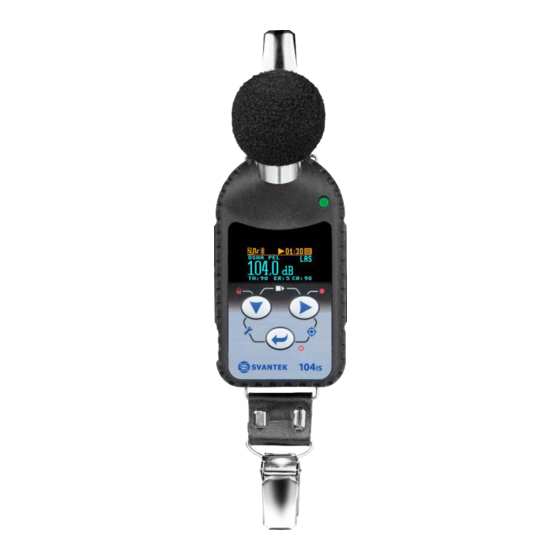
SV 104BIS User Manual GETTING STARTED YSTEM DESCRIPTION The following figure shows the SV 104BIS controls and ports: ST 104B microphone with SA 122BIS windscreen LED status indicator ➢ AMBER: stop mode ➢ GREEN: measuring ➢ RED: alarm/charging Mounting accessories... -
Page 20: Input / Output Interfaces
SV 104BIS side view – microphone connector Figure 3-2 communication charging electrical port connector Figure 3-3 SV 104BIS back view - charging and communication port (reserved for docking stations) Note: Full description of the connectors is given in Appendix C. -
Page 21: Windscreen
SV 104BIS User Manual INDSCREEN During use, it is strongly recommended that SV 104BIS is fitted with the supplied SA 122BIS antistatic windscreen. To calibrate the dosimeter, it is necessary to remove the windscreen to gain access to the microphone. It is not necessary to remove the windscreen to record the voice note comments. -
Page 22: Mounting And Positioning Sv 104Bis
Unless specified by local legislation, personal noise dosimeters should always be mounted on the shoulder, circa 10 cm from the most exposed ear, with the microphone approximately a few cm above the shoulder. SV 104BIS shape and microphone height ensures proper instrument position, see figure below. Figure 3-6... -
Page 23: Status Bar Icons
MEASURMENT TIME during measurement run. Figure 3-7 SV 104BIS display icons description Overload detector The instrument has the built-in overload detectors. Both A/D converter and input amplifier overload conditions are detected. The overload in the measurement channel (in its analogue part) and the overload of the analogue / digital converter are both detected. -
Page 24: Manual Control Of The Instrument
Note: To save power consumption and extend battery life SV 104BIS will automatically switch off the display after 30 seconds if no button on the keypad is pressed. The LED indicator will still inform the user about the current state of operation and any possible alarm conditions. -
Page 25: Alternate Key Functions
3… 2… 1… for the • Keyboard lock • Voice comment 3… 2… 1… for the key. If you release the key too early, SV 104BIS returns to the last used VIEW mode and the selected control is not executed. -
Page 26: Alternate Combined Keys Functions
SV 104BIS User Manual 3.8.3 Alternate combined keys functions Additionally, combined short press of two keys simultaneously (keypad icons marked with white colour) allow quick access to even more functionalities. Short press - Start/Stop MEASUREMENT Short press - Enter/Exit Short press –... -
Page 27: Three Instruments In One - Acoustic Profile Concept
HREE INSTRUMENTS IN ONE CONCEPT SV 104BIS is able to monitor and log noise by enabling up to three different parameter configuration settings, also referred to as “ACOUSTIC PROFILE”. One can set profile no 1 to run measurements using the OSHA HC (Occupational Safety and Health Administration - Hearing Conversation) parameters and at the same time set profile no 2 to monitor the noise with the OSHA PEL (Occupational Safety and Health Administration –... -
Page 28: Results List View Mode
SV 104BIS User Manual acoustic profile number measured parameter name profile preset name acronym for: parameter value weighting filter: A, C, Z current criteria status bar: THreshold, Exchange Rate, CRiterion level Figure 3-12 Primary ONE RESULT view 3.10.3 RESULTS LIST view mode To get information about a number of results at one time it is handy to switch to the “results list”... -
Page 29: 1/3-Octave Analysis Spectrum View Mode
SV 104BIS User Manual The results of 1/1-octave analysis (so-called spectrum) can be examined by the user on a display in the Spectrum VIEW presentation mode. 1/1-octave spectra for all 9 centre frequencies of pass-band filters together with the 3 TOTAL overall values measured with the user selected frequency weighting filters are presented in the Spectrum mode, if enabled in the configuration setup. - Page 30 SV 104BIS User Manual The instrument can also operate as a real time 1/3-octave band analyser (RTA). In addition, and if enabled, 1/3-octave analysis is performed in parallel with the dosimeter operations. All 1/3-octave digital pass-band filters (with 28 centre frequencies from 10 kHz down to 20 Hz; in base 10 system) are working in real-time with the broadband frequency weighting filters (Z, A or C) and the linear LEQ detector.
-
Page 31: Instrument Status View Mode And Bluetooth Security Pin Code
Apart from simple LED alarm indications (Chapter 3.6) there are a few alarm conditions when ALARM presentation screens will appear. During a measurement run SV 104BIS will immediately turn on the display at the time that the programmable alarm condition is exceeded. The detailed alarm state condition for each... - Page 32 SV 104BIS User Manual Two alarm conditions Alarm conditions detected in detected in profile no 1 each profile PROFILE list Figure 3-20 ALARM view screens Note: At any time when battery power is almost exhausted the “low battery” alarm screen may...
-
Page 33: Running And Operating Basic Procedures
SV 104BIS HARGING SV 104BIS can be charged only with the use of docking station for a single unit (1-bay docking station SB 104B-1) or for five units (5-bays docking station SB 104B-5). Both docking stations are equipped with the USB Type B connector and can be connected with a PC for data transfer with the SC 16 cable. -
Page 34: Before You Turn The Instrument On
PRECAUTIONS WHEN USING AND CHARGING LITHIUM BATTERIES” clause on page 5). Ensure the SV 104BIS is fully charged prior to use by installing it(them) at the Dock Station. Note: Charging is allowed only in safe area. See the SPECIAL PRECAUTIONS WHEN USING AND CHARGING LITHIUM BATTERIES clause on page 5. -
Page 35: Turning On/Off
(“Shutting down” 3… 2… 1… ) is displayed. Thus, SV 104BIS gives you time to decide if you really want to turn off the instrument. If you release the key too early, SV 104BIS returns to the last presented VIEW mode. -
Page 36: Battery Check
SV 104BIS User Manual ATTERY CHECK Observe the battery icon in the instrument’s icon status bar or press the key until the Instrument Status view mode is presented and check the battery state. If it is too low, charge the batteries (Chapter 4.1). -
Page 37: Measurement Setup - Basic Configuration
Unit label screen is moved with the keys. To exit the Unit Label screen just shortly press the key. Then SV 104BIS will return to the last presented VIEW mode. Note: The personalized Unit Name can be set arbitrarily with Supervisor software. -
Page 38: Calibration
ALIBRATION The SV 104BIS dosimeter is offered with the dedicated ST 104B MEMS microphone with ½” housing. The instrument is factory calibrated with the supplied microphone for the standard environmental conditions. Because the microphone sensitivity is a function of the temperature, ambient pressure and humidity, the absolute calibration of the measurement channel should be performed locally. - Page 39 (the default expected value of the Calibration Level set by the manufacturer of SV 104BIS is equal to 114 dB). 3. Switch on the calibrator and wait ca 30 seconds for the tone to stabilise before starting the calibration measurement.
- Page 40 Calibration - microphone not in tolerance screen 9. Post calibration. If enabled remotely, the post processing is performed automatically under acceptance of the calibration measurement. SV 104BIS automatically adds the results to the previously saved files. Before saving the calibration factor, the text “Post Calibration” appears.
-
Page 41: Voice Comments Recording
(“Voice comment” 3… 2… 1… ) is displayed. Thus, SV 104BIS gives you time to decide if you really want to record a voice comment. In case you release the key too early, SV 104BIS returns to the last used VIEW mode. -
Page 42: Before And After Measurement Run
(Chapter 3.10.6) required configuration setup is selected (Chapter 4.6) SV 104BIS is calibrated, because it affects the results (Chapter 4.7) the windscreen is put on because it protects the microphone from industrial environment such as dust and moisture or from effects of impact (Chapter 3.3). -
Page 43: Auto-Run Mode Information
(“Keyboard lock” 3… 2… 1… ) is displayed and the unit gives you time to decide if you really want to activate security lock. If you release the key too early, SV 104BIS returns to the last presented VIEW mode. -
Page 44: Control Of The Instrument Via Bluetooth ® Wireless Interface
SV 104BIS User Manual • Use the key to change the VIEW mode. Note: In most cases the keypad will be probably locked. To gain access to the results and unlock the keypad see Chapter 4.12. Note: After reviewing results remember to lock the keypad again in order to maintain the integrity of the measurement run by preventing uncontrolled access to the instrument. -
Page 45: Data Downloading And Uploading
SV 104BIS User Manual Figure 4-21 Disabling the Free Field filter 4.16 ATA DOWNLOADING AND UPLOADING Downloading and uploading data can be done with the use of docking stations and the Supervisor software (see Chapter 6.4.1). The docking stations exchange data with a PC by the USB protocol. -
Page 46: Assistant Mobile Application
SV 104BIS User Manual ASSISTANT MOBILE APPLICATION Assistant is an application for mobile devices (smartphones and tablets) running on Android platform (5.0 or higher) and iOS platform (9.0 or higher) that extends functionalities of SV 104BIS. The application uses the ® Bluetooth interface enabling current results to be previewed on a mobile device as well as controlling the measurement Start / Stop. -
Page 47: Connection Via Bluetooth
Note: You will not get access to the instruments that are under control of other simultaneously running Assistant applications on another mobile device. Note: It is recommended that SV 104BIS is in the locked mode to discourage the wearer from tampering and is described in Chapter 4.12. -
Page 48: Control Via Bluetooth
SV 104BIS User Manual ® ONTROL VIA LUETOOTH The Assistant application has two main screens: scanning/status screen and result view/control screen. Tapping the fields inside the instrument frame you can go to the instrument’s results view and measurement control screen. - Page 49 SV 104BIS User Manual Internal battery status of the selected instrument. The battery capacity is displayed in percentage. If battery is close to be empty its colour changes to red. Internal memory status of the selected instrument. The green area and the percentage display the empty memory capacity.
-
Page 50: Results View / Control Screen
SV 104BIS User Manual 5.3.2 Results view / control screen The result view/control screen enables you viewing measured results of the particular instrument and controlling the measurement. From this screen, you can Pause, Start or Stop a measurement run tapping the appropriate icon on the measurement control bar. -
Page 51: Sms And E-Mail Notifications
SV 104BIS User Manual Figure 5-5 Changing of results to be viewed After pressing the button, the pop-up menu appears in which you can: • Identify corresponded instrument. • Turn the instrument off. • Exit the application. After tapping the Identity this instrument position, the pop-up box with the current name of the corresponded instrument will appear. - Page 52 SV 104BIS User Manual The recipient and contents of the E-mail or SMS is defined by tapping the button, and then selecting the appropriate command from the pop-up menu. Figure 5-6 Sending e-mail Figure 5-7 Sending SMS...
-
Page 53: Checking The Software Version And Exiting The Application
SV 104BIS User Manual HECKING THE SOFTWARE VERSION AND EXITING THE APPLICATION To check the software version, tap the button in the lower left corner and select the About command. Figure 5-8 Checking the Assistant version To exit the application, tap the... -
Page 54: Supervisor Basic Operations
Figure 6-1 Choosing the Supervisor mode You can also switch between the modes when Supervisor is running by clicking the Svantek icon and clicking in the opened menu Run as Supervisor Advanced or Run as Supervisor Lite. Note: This User Manual describes the basic features of the Supervisor Lite mode and most important operations with the SV 104BIS instruments, like: instrument configuration, data download and report generation. -
Page 55: Supervisor Main Window
Figure 6-2 Supervisor main window When a connected Svantek instrument is detected by Supervisor, it is added to the Instruments panel. The currently selected instrument is in the orange frame. The instrument information is presented in the Inventory panel. - Page 56 SV 104BIS User Manual Clock – the date and time set in the real-time clock of the Svantek instrument; you can adjust it to • match the PC’s date and time by pressing the button. You can also right-click on the row corresponding to the selected instrument in order to open a context menu, allowing to specify the date and time manually.
- Page 57 The instrument’s name can be specified using the Edit name command. In order to unlock additional options or measurement functions of the SV 104BIS instrument that are available for purchase, use the Manage options/functions command in the instrument’s context menu. When you click on this command, Supervisor downloads a list of available functionalities from the connected instrument and displays it in the form of two lists: one for options and one for measurement functions.
-
Page 58: Editing The Instrument's Settings
Settings tab in the Instrument window . If you click the instrument in the Instruments panel the program automatically downloads the setup file from this instrument and shows its settings in the Settings panel. Setup Editor Using Supervisor to edit Svantek instruments’ settings Figure 6-8... -
Page 59: Editing Settings
SV 104BIS User Manual Using the buttons below the Setup Editor, you can: • choose up to ten previous settings that have been used most recently with this type of instrument, • Import a setup file from a PC catalogue, •... -
Page 60: Using Presets
The changes are automatically remembered by Supervisor. You can change the name of the preset using the button. Note: The three user-defined presets correspond only to the currently selected type of Svantek instrument. Different three presets are stored for each instrument type. -
Page 61: Profile Settings
6.3.5 Measurement parameters settings Within the measurement tab you can choose in which mode of operation the SV 104BIS should work: Dosimeter, or Dosimeter with 1/1-octave or 1/3-octave analysis. Note: Enabling 1/1 or 1/3-octave analysis shortens battery life, so take it into consideration... -
Page 62: Time-History Data Logging Settings
SV 104BIS User Manual Other basic parameters configuration is shown on the figure below: select measurement mode of operation Figure 6-12 Measurement configuration settings tab 6.3.6 Time-history data logging settings To enable logging the time-history data go to the “Time History” settings tab and switch the very first switch button on the left panel. -
Page 63: View Configuration
• In the right panel named “Display Results”, you will find a list of over a dozen measurement parameters, that can be configured to be presented on the SV 104BIS display, when you press key. See Appendix D to review acronyms for each parameter. -
Page 64: Spectrum Configuration
SV 104BIS User Manual 6.3.8 Spectrum configuration Real time 1/1 or 1/3-octave analysis is an additional optional feature. Therefore, it has its own settings tab. Within this tab there are the following panels: named “Data”: This configures the weighting filter that is to be used with octave calculation •... -
Page 65: Calibration
SV 104BIS User Manual 6.3.9.1 Calibration Sometimes it is required to perform so called post-calibration of the instrument. The Post Calibration position enables the user to perform additional calibration after a measurement session and add the results to the file saved in the memory. -
Page 66: Auxiliary Settings
4.12 how to lock and unlock the SV 104BIS instrument. If “Unlock on Key” is set to On, SV 104BIS will require special code to be input by pressing four keys defined in this panel in a particular sequence If “Unlock on Key” is set to Off, SV 104BIS can be locked/unlocked without providing Lock/Unlock sequence. -
Page 67: Auto-Run Settings (Timer, Pauses)
SV 104BIS User Manual Figure 6-20 Auxiliary settings panel 6.3.10 Auto-Run settings (timer, pauses) In the Pause panel the user may program five independent pauses in real time – Begin and End of the pause. The Timer panel enables the user to program the internal real time clock to act as a delayed start and stop timer. -
Page 68: Recording Options
6.3.11 Recording options Recording tap has two panels – Event Recording and Wave Recording. For SV 104BIS only the Wave Recording option is available. Note: The Wave Recording is an optional function and should be activated before use. Activation of the optional functions can be made with the use of the Supervisor software –... - Page 69 SV 104BIS User Manual There are four basic parameters of audio recording available for all modes: Wave File Format (PCM or Extensible), Filter (Z, A, CB), Sampling frequency (12kHz or 24kHz) and Signal Gain (from 0 dB to 35 dB).
-
Page 70: Working With Data Files
6.4.1 Downloading files In order to download files from the connected Svantek instrument(s), open the Download tab in the Instrument window. The Download panel contains a list of files stored in the instrument’s memory in the form of a table. Various types of files are displayed there, e.g., measurement files, wave files, etc. -
Page 71: Data Browser
6.4.2 Data Browser In order to view all the files downloaded from Svantek instruments and stored in the Supervisor’s database, open the Data Browser using the button located in the top-left corner of the Supervisor window. The Data Browser is composed of three panels: −... -
Page 72: File Manager
SV 104BIS User Manual − on the right side of the window, the File list panel contains a list of files belonging to a selected group and allows to open a file for further processing − below the file list panel, the File preview panel enables to preview data contained in a selected file. -
Page 73: File Details
(dropping files into Windows Explorer). Note: The catalogues for the downloaded files are created automatically in the Catalogue. Created catalogues by default have names of the instruments, for example, SV 104B, SV 104BIS, etc. Figure 6-28 Example of the Catalogue content −... - Page 74 SV 104BIS User Manual Filters Use these buttons to add selected files to the Flagged group Use this command to create a session using the selected file (you can also double-click the file) Figure 6-29 File details panel Setting flags...
-
Page 75: File Preview
SV 104BIS User Manual Creating reports You can generate a report of the selected file(s) based on some templates using the General report button. After pressing this button, you should select a template for the report. All reports are saved in the Summary reports sub-panel. -
Page 76: Using Assignments
Plot panel (on the right hand side of the Preview panel, displaying data in graphical form). 6.4.2.4 Using assignments Three types of additional information can be assigned to each file downloaded from a Svantek instrument: − Location (where the measurement was carried out), −... -
Page 77: Summary Reports
SV 104BIS User Manual Another method for assigning information to files is to drag & drop a file from the File details table to a particular item in the Assigned sub-tree in the Library. Notice that if you, for example, drop a file to a sub-sub-item corresponding to both a User and a Task, both these values will be assigned to that file. - Page 78 Figure 6-37 Summary report wizard initial window A template of the summary report consists of a set of parameters (i.e. the parameters of the Svantek instrument, parameters of the measurement, and measured quantities) to be displayed in numerical form, and another set of parameters to be displayed on a plot.
-
Page 79: Sessions And Reporting
After specifying the minimum and maximum date, press Finish to generate the report. ESSIONS AND REPORTING Sessions can be used to work with data downloaded from Svantek instruments and to create reports containing these data. 6.5.1 Creating and managing sessions To create a session, go to the Data Browser. - Page 80 SV 104BIS User Manual Template list Enabling validation tool Figure 6-40 Choosing post-processing template The template list consists includes predefined templates: Default template, templates related to the results type, for example, Noise dose (P1 ISO 9612 task); and templates created by the user, for example, New template.
-
Page 81: Validation Tool
SV 104BIS User Manual 6.5.2 Validation tool The Validation tool is used to check the correctness of the measured data and, if necessary, to reject "disturbances". After creating a session with the Use validation tool option, the logger results view will appear with the Validation tool open on the left enabling automatic searching for markers areas: •... -
Page 82: Session's Tollbar
SV 104BIS User Manual Clicking the left selector above the disturbances list header, you can apply the filter, for example, NoMotion, Audio event or High vibration level. Clicking the left button above the disturbances list header, you can select or deselect all items in the list. -
Page 83: Session Source Data
SV 104BIS User Manual 6.5.4 Session source data The measurement data used to create sessions are contained in files, stored in the Supervisor’s local database. Several files can be used to create a single session. A list of files which have been used to create the currently opened session is displayed in the Session data panel at the top-left corner of the window. - Page 84 SV 104BIS User Manual Click on the bar to hide this list Double-click to add a panel to the current session Figure 6-46 Add panel list of all panels available for the current data You can add any number of panels you want, including multiple panels of the same types. All panels added to the current session are listed in the Panels list, located at the left side of the window.
-
Page 85: Generating Reports From Sessions
SV 104BIS User Manual The available types of panels for the SV 104BIS instruments are listed in the below Table. For detailed panel description follow Supervisor User Manual. Icon Name Session header Instrument configuration Logger results Total results Logger statistics... - Page 86 SV 104BIS User Manual Click on the bar to hide this panel Double-click to open the report in MS Word, or right-click to access the context menu Figure 6-49 Reports panel By right-clicking you can open a context menu allowing for opening, renaming and deleting reports.
-
Page 87: 104Bis Maintenance
Do not keep the instrument for a long time discharged (see Chapter 7.7). • Charge the SV 104BIS instrument in a docking station before attempting to turn it on if the dosimeter has not been used for a prolonged period or was stored in a low battery state condition. -
Page 88: Periodic Testing
In case the windscreen is destroyed/lost by any accident, or it gets too dirty to afford the microphone the best protection then SVANTEK offers SA 122BIS_3 three pcs per pack (windscreens for the SV 104BIS dosimeter). To change the microphone, unscrew the windscreen first (Chapter 3.3). Then unscrew the microphone protective sleeve and pull the microphone to extract it. -
Page 89: Storing The Instrument
Generally, the SV 104BIS instrument should be stored at room temperature, charged to about 40 to 60% of capacity. • After use, it is best to charge SV 104BIS prior to storage for a prolonged period that is longer than 3 months. •... -
Page 90: Risk Assessment And Mitigation Of Risk
ENVIRONMENTAL PROTECTION MARKING OF THE UNIT, page HAZARDS related to reliable function, performance and wrong software setup are covered by: • Chapter 4, RUNNING AND OPERATING BASIC PROCEDURES, page • Chapter 6, SUPERVISOR BASIC OPERATIONS, page • Chapter 7, SV 104BIS MAINTENANCE, page... -
Page 91: Svantek Service
SV 104BIS User Manual SVANTEK SERVICE Should your SVANTEK professional measurement equipment need to be returned for repair or for calibration, please contact the service office at the following number or contact via the SVANTEK website. Service Office: +48 (22) 51-88-320 or +48 (22) 51-88-322. -
Page 92: Appendix Aremote Control
SV 104BIS User Manual APPENDIX A REMOTE CONTROL USB 2.0 interface is the serial one working with 480 MHz clock which enables one to control remotely the unit. Its speed is relatively high, and it ensures the common usage of USB in all produced nowadays Personal Computers. - Page 93 Example: The instrument sends the following sequence of characters as an answer for the mentioned above request: #1,U104,N12342,W1.08.1,Q0.01,M4,F2:1,F3:2,F1:3,J2:1,J3:2,J1:3,f1,C1:1,C0:2,C2:3,B0:1,B3:2,B15:3, b0,d1s,D10s,K5,L0:1,L0:2,L0:3,Y3,y0,XC115:1,XC115:2,XC115:3,Xl115:1,Xl115:2,Xl115:3,S0,T1,e480 ,c1:1,c1:2,c1:3,h0:1,h0:2,h0:3,x3:1,x3:2,x5:3; means that: • SV 104BIS is investigated (U104); • number is 12342 (N12342); • software version number is 1.08.1 (W1.08.1); • calibration factor is equal to 0.01 dB (Q0.01);...
-
Page 94: Function #2 - Measurement Results Read-Out In Dose Meter Mode
SV 104BIS User Manual • criterion level in profile 2 is chosen as 80 dB (c1:2); • criterion level in profile 3 is chosen as 80 dB (c1:3); • threshold level in profile 1 is None (h0:1); • threshold level in profile 2 is None (h0:2);... - Page 95 SV 104BIS User Manual time of the measurement (ccc – value in seconds); the Lpeak value (ccc – the value in dB); the Lmax value (ccc – the value in dB); the Lmin value (ccc – the value in dB);...
-
Page 96: Function #3 - Read-Out Of The Measurement Results In 1/1 Octave Or 1/3 Octave Mode
SV 104BIS User Manual #3 - R 1/1 OCTAVE UNCTION OUT OF THE MEASUREMENT RESULTS IN 1/3 OCTAVE MODE #3 function enables one to read out the current measurement results in 1/1 OCTAVE or 1/3 OCTAVE #3 function format is defined as follows:... -
Page 97: Function #5 - Statistical Analysis Results Read-Out
SV 104BIS User Manual where: fname - name containing not more than eight characters, offset - offset from the beginning of the file, length - number of bytes to read, #4,4; the current settings file, #4,4,?; size of the current settings file, #4,4,offset,length;... -
Page 98: Function #7 - Special Control Functions
SV 104BIS User Manual = 1 means "overload appeared", D6 = 1 reserved, D5 = 0 the instantaneous current result (RUN State), = 1 the final result (STOP State), D0 to D4 reserved bits. Note: There is not any succeeding transmission in the case when the Status Byte is equal to zero. - Page 99 SV 104BIS User Manual – minutes of the measurement stop, – day of week in which the measurement will be done: bit:0 – Monday, bit:6 – Sunday – maximum number of the measurement days, #7,AS, e,HH,MM,hh,mm,dW,mR; where: – On (e=1), Off (e=0), –...
- Page 100 SV 104BIS User Manual 0 – Off where: n 1 - On, This function returns battery voltage in 10 mV. #7,BV; Get number of records calibration history #7,CH; Response format: #7,CH,n; – number of records calibration history, where: n #7,CH,n;...
- Page 101 SV 104BIS User Manual #7,FT; This function returns file system on sd card in the format #7,FT,x;.where x denotes -1: no sd card, 2: FAT32. Reserved. #7,IC; #7,KL,x; This function locks ( x = 1 ) or unlocks ( x = 0 ) keyboard and returns the following sequence of characters: #7,KL;...
- Page 102 SV 104BIS User Manual Reserved. #7,SE; #7,SF; Reserved. This function returns statistical levels format #7,SL; #7,SL,sl1,sl2,sl3,sl4,sl5,sl6,sl7,sl8,sl9,sl10; This function sets statistical levels where sl_index is the statistical index, #7,SL,sl_index,sl_level; sl_level is the statistical level and returns the following sequence of characters: #7,SL;...
-
Page 103: Function #9 - Write-In The Data File Into The Internal Flash-Disc
SV 104BIS User Manual #7,US; This function returns unit subversion. This function returns USB voltage in 10 mV. #7,UV; This function returns the Bootstrap software version. #7,VB; This function returns the Hardboot software version. #7,VH; This function restart instrument. This function is not accepted while the instrument is in the RUN state. - Page 104 SV 104BIS User Manual 1) #D,c,?; this function returns the list of available disks in format: #D,c,<disk1>[,<disk2>[,<disk3>]]; 2) #D,d,?; this function returns the parameters of the working directory in format: #D,d,<disk>,<address>,<count>; 3) #D,d,<disk>,<address>; this function enables to change the working directory Response: #D,d;...
-
Page 105: Control Setting Codes
SV 104BIS User Manual A.10 ONTROL SETTING CODES The control setting codes used in the SV 104BIS instrument (the internal software revision 1.07.1) are given in the table below. Table A.1. Control setting codes Group Group name Code description code... - Page 106 SV 104BIS User Manual D0 - infinity (measurement finished by pressing the Stop or remotely - by sending S0 control code) Integration period Dnns - nn number in seconds Dnnm - nn number in minutes Dnnh - nn number in hours...
- Page 107 SV 104BIS User Manual x6:p - p: 1, 2, 3 - profile number T0 - switched off ([ ]) Logger T1 - switched on ([]) nn delay given in seconds (0 59) and Ynn - Delay in the start of measurement (60 ...
-
Page 108: Appendix Bdata File Structures
Each file containing data from the SV 104BIS instrument consists of several groups of words. In the case of the SV 104BIS (the internal file system rev. 1.07), there are two different types of files containing: the results stored in the file in the instrument’s logger (cf. App. B.2);... - Page 109 SV 104BIS User Manual Table B.1.1. SvanPC file header Word Name Comment number “SvanPC” 0..2 reserved reserved reserved reserved 6..15 Reserved reserved … … … Table B.1.2. File header Word Name Comment number [01, nn=header’s length] 0xnn01 1..4 FileName name of the file (8 characters)
- Page 110 SV 104BIS User Manual Table B.1.4. Calibration settings Word Name Comment number [47, nn=header’s length] 0xnn47 type of calibration performed prior to measurement: 0 - none PreCalibrType 1 - BY MEASUREMENT 3 - FACTORY CALIBRATION PreCalibrDate date of calibration performed prior to measurement (cf. App. B.4) PreCalibrTime time of calibration performed prior to measurement (cf.
- Page 111 SV 104BIS User Manual measurement input type: MeasureInput 2 - Microphone measurement range: Range 2 - SINGLE calibration flags: b0 - if set to 1: calibration coefficient is used b3 - if set to 1: overload occurred b7,b6,b5: type of the result Lden 000 –...
- Page 112 SV 104BIS User Manual profile threshold level for PTC calculation 70 ÷ 140 dB (*10) the 2 PEAK Th. Level[2] profile threshold level for PTC calculation 70 ÷ 140 dB (*10) the 3 PEAK Th. Level[3] the 1 profile criterion level (only DOSE METER):...
- Page 113 SV 104BIS User Manual The start time of the pause no. 1 in format 0xhhmm hh – hour PauseBegin[1] mm – minute The end time of the pause no. 1 in format 0xhhmm: hh – hour PauseEnd[1] mm – minute Programmable pause no.
- Page 114 SV 104BIS User Manual source of the triggering signal: TriggerSource 0 - Leq(1) the Leq result from the first profile level of triggering: TriggerLevel 50 ÷ 136 dB (*10) gradient of triggering: TriggerGrad 1 dB/ms ÷ 100 dB/ms pretrigger time given in 10ms...
- Page 115 SV 104BIS User Manual logger contents in the 1 profile defined as a sum of: 0 - none, 1 - Lxpeak 2 - Lxymax BufferP[1] 4 - Lxymin 8 - Lxyeq 16 - LAV filter type for Peak result calculation in the 1...
- Page 116 SV 104BIS User Manual filter type in the 3 profile: 1 - Z, FilterP[3] 2 - A, 3 - C logger contents in the 3 profile defined as a sum of: 0 - none, 1 - Lxpeak 2 - Lxymax...
- Page 117 SV 104BIS User Manual 0 – PSEL result not displayed, 1 - PSEL result displayed PSEL 0 – Ltm3 result not displayed, 1 - Ltm3 result displayed Ltm3 0 – Ltm5 result not displayed, 1 - Ltm5 result displayed Ltm5 0 –...
- Page 118 SV 104BIS User Manual Table B.1.15. Header of the file from the logger Word Name Comment number [0F, nn=header’s length] 0xnn0F BuffTSec logger time step - full seconds part logger time step - milliseconds part BuffTMilisec LowestFreq the lowest 1/1 OCTAVE or 1/3 OCTAVE frequency (*100 Hz)
- Page 119 SV 104BIS User Manual Result[1][6] Lxyeq value in the 1 profile (*100 dB) Lc-a (LCeq-LAeq) value (*100 dB) Result[1][7] Result[1][8] Ltm3 value in the 1 profile (*100 dB) Result[1][9] Ltm5 value in the 1 profile (*100 dB) Result[1][10] LAV value in the 1...
- Page 120 SV 104BIS User Manual Result[3][7] reserved Result[3][8] Ltm3 value in the 3 profile (*100 dB) Result[3][9] Ltm5 value in the 3 profile (*100 dB) Result[3][10] LAV value in the 3 profile (*100 dB) Result[3][11] TLAV value in the 3 profile (*100 dB)
- Page 121 SV 104BIS User Manual number of TOTAL values: 3 NOctTot 1/1 octave[i] value (*100 dB); i=1÷NOct+NoctTot (1÷13) 5÷20 Octave[i] … … … Table B.1.20. 1/3 OCTAVE analysis results (saved in Summary Results Record) Word Name Comment number [block_id, nn=block_length] 0xnn10 - averaged spectrum results,...
- Page 122 SV 104BIS User Manual Table B.1.22. SETUP file Word Name Comment number [20, 00=block’s length in the second word] 0x0020 BlockLength length of the block 2..BlockLen SetupTextData saved setup values gth-1 Table B.1.23. File-end-marker Word Name Comment number 0xFFFF file end marker Table B.1.24.
-
Page 123: Structure Of The File Containing Results From Loggers File
SV 104BIS User Manual ’ TRUCTURE OF THE FILE CONTAINING RESULTS FROM LOGGER S FILE SvanPC file header - cf. Tab. B.1.1. File header - cf. Tab. B.1.2. Unit and software specification - cf. Tab. B.1.3. Calibration settings - cf. Tab. B.1.4. -
Page 124: Record With The State Of The Markers
SV 104BIS User Manual • results of the measurement from the second profile if the corresponding LOGGER position was active (BufferP [2] in Tab. B.1.12); up to five words are written: <result1> - Lxpeak result, depending on the value of BufferP[2] (cf. Tab. B.1.12) <result2>... -
Page 125: Record With The Breaks In The Results Registration
SV 104BIS User Manual B.2.1.3 Record with the breaks in the results registration The record with the breaks in the results registration consists of four words: <0xB0ii> <0xB1jj> <0xB2kk> <0xB3nn> in which ii, jj, kk, nn bytes denote 4-bytes counter of left or skipped records: nnkkjjii (ii is the least significant byte, nn –... -
Page 126: Record With Name Of The Comment File
SV 104BIS User Manual The HEADER format is as follows: where: b15 - b14 - b13 - b12 - b11 - header type: 0 - HS 1 - HE b10 - b9 - b8 - b15÷b8 – HS (0xC3), HE (0xCB) b7÷b0 –... - Page 127 SV 104BIS User Manual Structure of the SETUP file SvanPC file header - cf. Tab. B.1.1. File header - cf. Tab. B.1.2. Unit and software specification - cf. Tab. B.1.3. SETUP DATA - cf. Tab. B.1.22. File-end-marker - cf. Tab. B.1.23.
-
Page 128: Appendix Ctechnical Specifications
Statement of performance The SV 104BIS dosimeter meets also requirements of the: IEC 61252 ed1.2 (2017) SV 104BIS dosimeter with all listed below accessories meets requirements of IEC 61672-1:2013 for Class 2 Group X instruments. SV 104BIS dosimeter meets also requirements of the next standards: ANSI/ASA S1.25-1991 (R2017), IEC 61010-1 (2010), ANSI/UL 61010-1 and CAN/CSA C22.2 No 61010-1;... - Page 129 SV 104BIS User Manual Measured quantities The measured quantities for DOSE METER mode are: Time, Lpeak, Lmax, Lmin, SPL (L), DOSE, D_8h, PrDOSE, Lav, Leq, SEL (LE), SEL8, E, E_8h, LEPd, PSEL, Ltm3, Ltm5, Leq statistics (Ln), PTC, PTP, ULT, TWA, PrTWA, Lc-a.
- Page 130 SV 104BIS User Manual Measurement frequency range of the acoustic pressure (-3 dB): 20 Hz – 10000 Hz Basic measurement error of the acoustic pressure < 1 dB (measured for the reference conditions, see below). h ÷ 99.99 Pa Noise exposure values displayed range 0.01Pa...
- Page 131 SV 104BIS User Manual Time weighting characteristics (Exponential averaging) “S“ according to IEC 61672-1:2013 Class 2, Equivalent Time Constant 1000 ms Slow “F” according to IEC 61672-1:2013 Class 2, Equivalent Time Constant 125 ms Fast “I” according to IEC 61672-1:2013 Class 2, Equivalent Time Constant 35 ms, Hold Time...
- Page 132 In addition, with microphone cable, the maximum susceptibility is achieved when the dosimeter and cable is placed along field and the cable is coil as solenoid. Figure C.1 SV 104BIS placed in magnetic field test coil in the direction of maximum response...
- Page 133 Note: Maximum sound pressure level that can affect the microphone without destroying the microphone: 160 dB. ST 104B and SV 104BIS frequency characteristics The instrument should be mounted so that the microphone diaphragm is perpendicular to the direction of the sound wave.
- Page 134 0.00 0.00 0.00 0.00 0.13 0,54 1.50 3.94 Free Field corrections Table C.3 Typical ST 104B and SV 104BIS frequency characteristics Frequency ST 104B Free Field SV 104BIS Free Compensated case Uncertainty response Field compensated effect (IEC 62585:2012) response [Hz]...
- Page 135 SV 104BIS User Manual Frequency ST 104B Free Field SV 104BIS Free Compensated case Uncertainty response Field compensated effect (IEC 62585:2012) response [Hz] [dB] [dB] [dB] [dB] 0.03 -0.02 -0.05 0.25 0.03 -0.09 -0.12 0.25 0.04 -0.11 -0.15 0.25 0.04 -0.02...
- Page 136 SV 104BIS User Manual Frequency ST 104B Free Field SV 104BIS Free Compensated case Uncertainty response Field compensated effect (IEC 62585:2012) response [Hz] [dB] [dB] [dB] [dB] 1995 -0.63 -0.10 0.53 0.25 2054 -0.62 -0.02 0.60 0.25 2113 -0.68 -0.26 0.41...
- Page 137 SV 104BIS 0.00 0.00 0.00 0.00 0.00 0.00 1.07 3.18 8.68 Free Field corrections Directional characteristics of SV 104BIS Directional response for dosimeter SV 104BIS with microphone ST 104B and SA 122BIS windscreen (symmetrical axis) for specified frequencies (Table C.5):...
- Page 138 SV 104BIS User Manual Figure C.3 Total directional characteristics (symmetrical axis) The round charts show the directional characteristic, and the charts below shows the errors for particular angles (note: limits are for class 1).
- Page 139 SV 104BIS User Manual...
- Page 140 SV 104BIS User Manual...
- Page 141 SV 104BIS User Manual...
- Page 142 SV 104BIS User Manual...
- Page 143 SV 104BIS User Manual...
- Page 144 SV 104BIS User Manual...
- Page 145 SV 104BIS User Manual Table C.5 Directional response for SV 104BIS with microphone ST 104B and SA 122BIS windscreen (symmetrical axis) Angle [˚] f [Hz] 0-10 10-20 20-30 30-40 40-50 50-60 60-70 70-80 80-90 -0.0 -0.0 -0.1 -0.1 -0.1 -0.1 -0.1...
- Page 146 SV 104BIS User Manual 9000 -0.1 -0.1 -0.6 -1.6 -2.9 -4.1 9500 -0.3 -0.6 -0.7 -0.6 -0.5 -0.4 -1.2 -2.6 -3.2 10000 -0.3 -1.1 -1.6 -1.6 -1.8 -1.9 -2.4 -3.4 -3.8 Angle [˚] f [Hz] 90-100 100-110 110-120 120-130 130-140...
- Page 147 -1.0 -0.4 -0.5 -0.6 -0.5 -0.2 -0.0 10000 -3.1 -1.9 -1.3 -1.5 -1.4 -1.0 -0.5 -0.1 Directional response for dosimeter Class SV 104BIS with microphone ST 104B and SA 122BIS windscreen (for orthogonal asymmetrical axis) for specified frequencies (Table C.6):...
- Page 148 SV 104BIS User Manual Figure C.4 Total directional characteristics (asymmetrical axis)
- Page 149 SV 104BIS User Manual The round charts show the directional characteristic, and the charts below shows the errors for particular angles (note: limits are for class 1).
- Page 150 SV 104BIS User Manual...
- Page 151 SV 104BIS User Manual...
- Page 152 SV 104BIS User Manual...
- Page 153 SV 104BIS User Manual...
- Page 154 SV 104BIS User Manual...
- Page 155 SV 104BIS User Manual Table C.6 Directional response for SV 104BIS with microphone ST 104B and SA 122BIS windscreen (asymmetrical axis) Angle [˚] f [Hz] 0-10 10-20 20-30 30-40 40-50 50-60 60-70 70-80 80-90 -0.0 -0.0 -0.1 -0.1 -0.1 -0.1 -0.1...
- Page 156 SV 104BIS User Manual 1000 -0.1 -0.1 -0.1 -0.0 -0.0 1250 -0.4 -0.4 -0.4 -0.4 -0.4 -0.5 -0.5 -0.5 -0.5 1600 -0.5 -0.6 -0.6 -0.6 -0.6 -0.5 -0.5 -0.5 -0.5 2000 -0.7 -0.7 -0.7 -0.7 -0.7 -0.6 -0.6 -0.5 -0.5 2240 -0.9...
- Page 157 SV 104BIS User Manual 2800 -1.0 -0.8 -0.7 -0.5 -0.4 -0.3 -0.2 -0.1 -0.1 3150 -0.4 -0.2 -0.0 3550 -0.3 -0.5 4000 4500 -0.6 -0.4 -0.1 -0.1 -0.0 -0.0 5000 -0.5 -0.2 -0.2 -0.2 -0.3 -0.3 -0.2 -0.2 -0.1 5600 -0.5...
-
Page 158: Specification Of The Sv 104Bis As 1/1 And 1/3 Octave Analyser
1/3 OCTAVE ANALYSER PECIFICATION OF THE The SV 104BIS instrument operating as 1/1 OCTAVE or 1/3 OCTAVE sound analyser meets the IEC 61260-1:2014 standard for the pass band filters. Note: Simultaneously to the frequency analysis SV 104BIS operates as a Dosimeter! - Page 159 SV 104BIS User Manual Calibration (electrical) 114.0 dB (ref. 1μV Calibration level < 0.1 dB (for the temperature T = +23°C 5°C for the Basic accuracy in the bandwidth 20 Hz ÷ 10 kHz sinusoidal signal 114 dB...
- Page 160 SV 104BIS User Manual 1/1-octave filters 9 filters with centre frequencies from 31.5 Hz to 8 kHz (base 10), meeting IEC 61260-1:2014 for Class 1. 8.0 kHz 1/1 octave filter 4.0 kHz 1/1 octave filter 2.0 kHz 1/1 octave filter...
- Page 161 SV 104BIS User Manual 1.0 kHz 1/1 octave filter 500 Hz 1/1 octave filter 250 Hz 1/1 octave filter...
- Page 162 SV 104BIS User Manual 125 Hz 1/1 octave filter 63.0 Hz 1/1 octave filter 31.5 Hz 1/1 octave filter...
- Page 163 SV 104BIS User Manual 1/3-octave filters 28 filters with centre frequencies from 20 Hz to 10 kHz (base 10), meeting IEC 61260-1:2014 for Class 1. 1/3 octave filters for 8.0 kHz 1/1 octave filter 1/3 octave filters for 4.0 kHz 1/1 octave filter...
- Page 164 SV 104BIS User Manual 1/3 octave filters for 1.00 kHz 1/1 octave filter 1/3 octave filters for 500 Hz 1/1 octave filter 1/3 octave filters for 250 Hz 1/1 octave filter...
- Page 165 SV 104BIS User Manual 1/3 octave filters for 125 Hz 1/1 octave filter 1/3 octave filters for 63.0 Hz 1/1 octave filter 1/3 octave filters for 31.5 Hz 1/1 octave filter...
- Page 166 SV 104BIS User Manual 1/3 octave filters for 16.0 Hz 1/1 octave filter...
-
Page 167: Frequency Characteristics Of The Implemented Digital Filters
SV 104BIS User Manual REQUENCY CHARACTERISTICS OF THE IMPLEMENTED DIGITAL FILTERS Digital weighting filters implemented in dose and octave mode Z Filter: Class 2 according to the IEC 61672-1:2013 standard. A Filter: Class 2 according to the IEC 61672-1:2013 standard. - Page 168 SV 104BIS User Manual C Filter Class 2 according to the IEC 61672-1:2013 standard. The weighting filters, which are available in sound modes (Z, A, and C) are selected in thru SUPERVISOR software under the settings window.
-
Page 169: General Specification Of The Sv 104Bis
SV 104BIS User Manual SV 104BIS ENERAL SPECIFICATION OF THE Signal input The input of the measured signal (mounting head): Figure C.10 ST 104B microphone connector (mounting head outer view) Table C.6 Pin out of the microphone connector Pin Number Function “SIGNAL”... - Page 170 SV 104BIS User Manual Communication Interface and external Power Connector The SV 104BIS electrical interface enables remote control of the instrument and data transfer up to attainable with 3 MHz clock. “Client” communication port Figure C.11 Power and Communication Port (external bottom view) Table C.7 Pin-out of the electrical interface...
- Page 171 Range: typically, ≤50m line-of-sight and depending on local RF conditions. The instrument contains a wireless transmission module, BGM121 from Silicon Laboratories. Copies of the modules regional approvals certificates may be obtained from Svantek or Silicon Laboratories. • Declaration ID: D033250, Controller Subsystem Qualified Design ID: 88831 FCC and ISEDC This product contains an FCC and Industry Canada certified Bluetooth®...
- Page 172 SV 104BIS User Manual test report. This transmitter must not be co-located or operating in conjunction with any other antenna or transmitter except in accordance with FCC multi-transmitter product procedures. ISEDC Statements: This radio transmitter has been approved by Industry Canada to operate with its embedded antenna. Other antenna types are strictly prohibited for use with this device.
-
Page 173: Appendix Ddefinitions And Formulae Of Measured Values
SV 104BIS User Manual APPENDIX D DEFINITIONS AND FORMULAE OF MEASURED VALUES ASIC TERMS AND DEFINITIONS Current time period of the measurement in seconds. Last second of the measurement. Exposure time in seconds (time period during which a person is exposed to the action of noise). - Page 174 SV 104BIS User Manual Value of q is used in the calculations of DOSE, D_8h and LAV is taken from the formula Threshold sound level set in the Threshold Level via the SUPERVISOR software. The available values are as follows: None, 60dB up to 90dB in 5 dB steps.
-
Page 175: Definitions And Formulas Of The Slm Function Results
SV 104BIS User Manual EFINITIONS AND FORMULAS OF THE FUNCTION RESULTS The instrument calculates the sound measurement results for three profiles. The calculation flow diagram for one profile is presented below: DOSE results max, min, L, tm3, τ = Slow p(t) wτ... - Page 176 SV 104BIS User Manual L(A/C/Z)(S/F/I) The lowest time weighted sound level (Min) expressed in dB, within a stated time interval, for frequency weightings A, C, Z and time weightings F, S, I symbols are LAFmin, LASmin, LCFmin, LCSmin etc. L(A/C/Z)(S/F/I)
-
Page 177: Definitions And Formulas Of The Additional Dosimeter Function Results
SV 104BIS User Manual EFINITIONS AND FORMULAS OF THE ADDITIONAL OSIMETER FUNCTION RESULTS − DOSE Quantity of noise received by the worker, DOSE expressed as the percentage of the whole day acceptable value. − D_8h Quantity of noise received by the worker ... - Page 178 SV 104BIS User Manual PTC result expressed in percent. Upper Limit Time: the time that the SPL exceeded the “ULT Threshold Level” set during configuration. • Time Weighted Average is the average A- Sound levels above weighted sound level for a nominal 8-hour...
-
Page 179: Statistical Levels - Ln Definition
SV 104BIS User Manual – L TATISTICAL LEVELS N DEFINITION The noise level L(t) is the continuous random variable. The probability that the temporary noise level L(t) belongs to the interval is called the class density and it can be expressed by the equation: t ... - Page 180 SV 104BIS User Manual...
Need help?
Do you have a question about the SV 104BIS and is the answer not in the manual?
Questions and answers