
Related Manuals for Svantek SV 100A


Summary of Contents for Svantek SV 100A
- Page 1 USER MANUAL SV 100A WHOLE-BODY VIBRATION DOSIMETER Warsaw, 2024-07-31 Copyright © 2024 SVANTEK. Rev.1.03 All rights reserved.
- Page 2 Svantek provides this document “as is”, without warranty of any kind, either expressed or implied, including, but not limited to, its particular purpose. Svantek reserves the right to make improvements and/or changes to this manual, or to the products and/or the programs described in this manual, at any time.
- Page 3 SV100A User Manual CONTENTS INTRODUCTION Vibration risk and its assessment SV 100A as a new generation vibration exposure meter SV 100A SYSTEM DESCRIPTION SV 100A key features Kit components Related optional equipment & accessories Instrument Software (Firmware) options available GETTING STARTED...
- Page 4 Session source data Session’s Tollbar 5.6.3 5.6.4 Session Panels 5.6.5 Generating reports from sessions ASSISTANT MOBILE APPLICATIONS Installing the Svantek application on a mobile device Assistant Pro 6.2.1 Description of the status icons 6.2.2 Controlling the instrument 6.2.3 Activating optional functions 6.2.4...
- Page 5 A.8. Function #9 - write-in the data file into the internal flash-disc A.9. Control setting codes APPENDIX B. DATA FILE STRUCTURES B.1. General structure of the SV 100A file B.2. Structure of the file containing results B.2.1. The contents of the files in the logger B.2.1.1.
- Page 6 SV100A User Manual D.3. Definitions and formulas of the Whole-Body vibration results DECLARATION OF CONFORMITY...
- Page 7 SV 100A as a new generation vibration exposure meter The new SV 100A is a wireless whole-body vibration meter suitable for whole-body measurements in accordance with ISO 2631-1 and European Parliament Directive 2002/44/EC. Suitable for both seat and seat- back measurements, it uses the latest technology and is easy to use.
- Page 8 WAV format in accordance to ISO 2631-5 that is compatible with popular recalculation software. The SV 100A is fully configurable using the Supervisor software. It can be quickly and easily set up for all the weighting filters required by ISO standards for estimating of the effects of vibration on health, comfort, perception and motion sickness.
- Page 9 • SA 54 – charger/power supply for SV 100A • SC 56 - mini USB 2.0 cable • SA 145 - carrying case for SV 100A instrument and accessories (waterproof) • Screw for fixing SV 100A to SV 111 • Mounting belt to SV 100A...
- Page 10 Related optional equipment & accessories • SV 111 – Vibration calibrator for in-situ check per ISO 8041:2021 • SA 136 – Calibration adapter for SV 100A periodical verification Instrument Software (Firmware) options available • SF 100A_OCT – 1/1 Octave real time analysis option •...
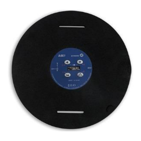
- Page 11 SV100A User Manual GETTING STARTED SV 100A control panel, interface The following Figure shows controls and connections of the SV 100A. Display Keypad 128 x 64 pixel resolution mini USB connector (charging, and data download) Figure SV 100A front view...
- Page 12 Note: To reduce power consumption and prolong battery life, SV 100A will automatically turns off the display after 30 seconds if no key is pressed on the keypad. 3.4.1 Primary key functions The following primary (short-press) control buttons are located on the front of the instrument: <SCROLL>...
- Page 13 SV100A User Manual Control keypad on the front panel – primary key functions Figure 3-2 keys allow you to: scroll down through results in the RESULTS VIEW modes, scroll down and up through the Calibration menu items, scroll down and up through setups in the Load Setup menu, decrease and increase the values of the Level parameter in the Calibration axis screens.
- Page 14 USB port or the SA 54 charger. When SV 100A is connected to a USB port or USB charger, it will automatically switch on during charging and display the status of the instrument’s internal battery. SV 100A will display ‘Fully charged’ when charging is complete.
- Page 15 (“Shutting down” 3… 2… 1… ). This gives you time to decide if you really want to switch off the instrument. If you release the key too early, SV 100A will return to the last VIEW mode displayed.
- Page 16 SV100A User Manual Starting and stopping measurement run START: Before starting a measurement, ensure that: the instrument is switched on, there is sufficient battery operating life and free memory by checking the status screen, the required configuration setup is selected, the instrument is calibrated as this will affect the results.
- Page 17 BASIC OPERATION OF THE INSTRUMENT VIEW modes The SV 100A provides many measurement results for the operator to review. For this reason, all information is clearly organised manner as VIEW modes for each channel. The VIEW mode is a way of presenting measurement results to the operator. In other words, when you change the VIEW mode, certain measurement parameters and status information are presented differently to suit the user's needs.
- Page 18 SV100A User Manual The Basic View mode is a primary measurement mode and it can be enabled or disabled like any other measurement mode, but if all modes are disabled, the Basic View mode will be active. In Basic View mode, any measurement result can be displayed and selected using the key.
- Page 19 ALARM screen review There are a two alarm conditions (EAV and ELV) when the ALARM screen appears. During a measurement, SV 100A will immediately switch on the display when the programmable alarm condition is exceeded. Press any key, to acknowledge the information.
- Page 20 Standards to which the instrument conforms: ISO 8041:2021 The Unit Label screen is scrolled down and up using the keys. To exit the Unit Label screen, press and release the key. SV 100A will then return to the last VIEW mode displayed. Note: The personalised Unit Name can be set using the Supervisor software.
- Page 21 In this case, the SA136 calibration adapter should be used to mount the accelerometer on a vibration table. If you have the SV 111 calibrator supplied by Svantek, you can check and calibrate the SV 100A without removing the accelerometer.
- Page 22 If it is necessary to perform a so-called post-calibration of the instrument (if post-calibration is pre-programmed in the configuration setup), SV 100A automatically adds the calibration factor to the header of the result files. This doesn't change the stored results and gives the user the possibility to compare the possible changes of...
- Page 23 The Factor item indicates the current calibration factor. 3. Mount the triaxial accelerometer or SV 100A to the SV 111 calibrator as shown above. 4. Switch on the calibrator and allow it to stabilise for approximately 30 seconds before starting the calibration measurement.
- Page 24 SV 100A will return to the last VIEW mode displayed. Unlocking SV 100A: SV 100A can be unlocked by a sequence of keys programmed via Supervisor or Assistant Pro. To unlock the instrument, press the keys in the correct sequence.
- Page 25 SV100A User Manual Measurement procedures For vibration measurements, the instrument should preferably be placed on the vehicle seat or backrest at the beginning of a shift and collected at the end of the entire shift. If a shorter period is sampled, care should be taken to ensure that the result is representative of the whole shift exposure.
- Page 26 • Plug the opposite end of the cable (mini-USB) into the instrument itself • SV 100A is powered and charged directly through the computer; thus, you do not need separate charger. The instrument will be switched on automatically • Run the Supervisor software and select its mode – Advanced or Lite.
- Page 27 Figure 5-2 Supervisor main window When a connected Svantek instrument is detected by Supervisor, it is added to the Instruments panel. The currently selected instrument is shown in the orange frame. The instrument information is displayed in the Inventory panel.
- Page 28 Name – the name of the instrument. • Clock – the date and time set in the real-time clock of the Svantek instrument; you can adjust it to the PC’s date and time by pressing the button. You can also right-click on the row corresponding to the selected instrument to open a context menu that allows you to set the date and time manually.
- Page 29 Inventory panel menu Unlocking optional functions To unlock additional options or measurement functions of the SV 100A instrument that are available for purchase, use the Manage options/functions command in the instrument’s context menu. When you click on this command, Supervisor downloads a list of available functionalities from the connected instrument and displays it in the form of two lists: one for options and one for measurement functions.
- Page 30 Settings tab in the Instrument window. When you click on the instrument in the Instruments panel, the program automatically downloads the setup file of this instrument and displays its settings in the Settings panel. Setup Editor Using Supervisor to edit Svantek instruments’ settings Figure 5-7...
- Page 31 SV100A User Manual The buttons below the Setup Editor allow you to: • select up to ten previous settings that were last used with this type of instrument, • Import a setup file from a PC catalogue, • Export the current settings as a setup file to a PC catalogue, •...
- Page 32 SV100A User Manual 5.4.3 Dosimetry settings The Dosimetry tab contains two panels: Measurement and Exposure Limits. There are predefined parameters with grey text. Other parameters must be set up by the user. In the Measurement panel, you can select the function: Dosimeter, Dosimeter and 1/1 Octave or Dosimeter and 1/3 Octave.
- Page 33 SV100A User Manual • The Force Detector Mode parameter defines the mode of the force detector that detects the driver’s sitting position. If Marker is selected, the marker is recorded when the driver sits down and the marker recording is stopped when the driver stands up. If Pause is selected, the measurement starts when the driver sits down and pauses when the driver stands up.
- Page 34 SV100A User Manual Figure 5-11 Channels configuration settings tab Since the axes orientation is fixed (X - forward/backward, Y - sideways, Z - vertical), it is necessary to redefine the axes if the instrument orientation changes. The Axes Orientation position allows the axes orientation to be adapted to the instrument position: •...
- Page 35 SV100A User Manual The instrument enables also additional registration of some results with the step defined by the Logger Step parameter (from 100 milliseconds to 1 hour) called Logger results or Time History Results (PEAK, P-P, MTVV, aw, VDV, awv). Therefore, it is possible to save in parallel two sequences of measured results with different intervals –...
- Page 36 • In the right-hand panel Display Results, you will find a list of over a dozen measurement results that can be displayed on the SV 100A display when the key is pressed. See Appendix D for the acronyms of each result.
- Page 37 SV 100A will lock the keypad each time a measurement run is started (see chapter how to lock and unlock SV 100A). SV 100A requires a special code to be entered by pressing four keys defined in this panel in sequence. In the Auxiliary panel, you can: •...
- Page 38 SV100A User Manual 5.4.8 Auto-Run settings The Auto-Run settings tab contains two panels: Pause, which allows you to program five independent pauses in real time, and Timer, which allows you to program the internal real-time clock to act as a delayed start and stop timer.
- Page 39 SV100A User Manual The signal can be recorded in various ways (Recording Mode), during the Whole Measurement or triggered with the Slope or Level trigger. You can set Sampling frequency (750 Hz) and weighting Filter (Unweighted or BL). Note: Recording is an optional function and should be activated before use. The optional functions can be activated using the Supervisor software (see Chapter 5.3).
- Page 40 SV100A User Manual Figure 5-18 Recording on trigger configuration Trigger Level + / Trigger Level – modes mean that the audio recording starts when the Trigger Source measured with the Step period (with a value equal to the Logger step, 5 ms, 100 ms or 1 s) is greater/less than the threshold (Trigger Level).
- Page 41 5.5.1 Downloading files To download files from the connected Svantek instrument(s), open the Download tab in the Instrument window. The Download panel contains a list of files stored in the instrument’s memory in the form of a table. It shows different types of files, e.g.
- Page 42 You can show/hide the File operations panel by clicking on the File operations in progress tab. 5.5.2 Data Browser To view all files downloaded from Svantek instruments and stored in the Supervisor database, open the Data Browser using the button in the top left corner of the Supervisor window.
- Page 43 SV100A User Manual The Data Browser consists of three panels: − On the left side of the window, the File manager panel contains a list of all the files stored in the Supervisor database and allows you to select a group of files to view in detail. −...
- Page 44 (dropping files into Windows Explorer). Note: The catalogues for the downloaded files are automatically created in the Catalogue. By default, the catalogues created are named after the instruments, e.g. SV 100A, etc. Figure 5-24 Example of the Catalogue content −...
- Page 45 SV100A User Manual 5.5.2.2 File details The File details panel contains a table listing the files corresponding to the selected item in the File manager. The files corresponding to all the sub-items of the selected item are also displayed in the Files details panel. Files can be further processed by using them for sessions.
- Page 46 SV100A User Manual Note: Exporting measurement files with comments attached (e.g., WAV files) automatically exports the comment files as well. To export a single file without the attached comments, use the drag and drop technique with the CTRL key held down. Creating reports The Generate report button allows you to create a report of the selected file(s) based on a number of templates.
- Page 47 Plot panel (on the right-hand side of the Preview panel, which displays data in graphical form). 5.5.2.4 Using assignments Three types of additional information can be associated with each file downloaded from a Svantek instrument: − Location (where the measurement was made), −...
- Page 48 SV100A User Manual Another method of assigning information to files is to drag and drop a file from the File details table onto a particular item in the Assigned sub-tree in the Library. Note that if, for example, you drop a file on a sub-sub- item that corresponds to both a User and a Task, both of these values will be assigned to the file.
- Page 49 Figure 5-33 Summary report wizard initial window A summary report template consists of one set of parameters (i.e. Svantek instrument parameters, measurement parameters and measured quantities) to be displayed in numerical views and another set of parameters to be displayed in graph views. To create a template, first specify the application for which you want to use it for, as this determines the availability of certain parameters.
- Page 50 After specifying the minimum and maximum dates, press Finish to generate the report. Sessions and reporting Sessions can be used to work with data downloaded from Svantek instruments and to create reports using this data. 5.6.1 Creating and managing sessions To create a session, go to the Data Browser.
- Page 51 SV100A User Manual Figure 5-36 Choosing post-processing template Each new session creates a tab in the bar at the top of the application window. To open a session, click the tab. Right-clicking on a tab opens a context menu that allows you to specify a custom name for a session or to close it.
- Page 52 SV100A User Manual Once a session is created, you cannot change its data source. If you want to use different files in a session, you must create a new session with those files. Session’s Tollbar 5.6.3 template manager change sound units report options change vibration zoom...
- Page 53 SV100A User Manual 5.6.4 Session Panels Panels are the basic building blocks of the reports created using Supervisor sessions. They can be used to configure the way data is displayed in the report. List of all available panels List of panels in the current session Figure 5-40 Panels in the Session window...
- Page 54 Click here to expand / hide Configurator Figure 5-41 Configurator tool The panel types available for the SV 100A instruments are listed in the table below. For a detailed description of the panels, refer to the Supervisor User Manual. Icon Name...
- Page 55 SV100A User Manual The generated file will contain a start page and all the contents of the panels (in the same order and with the same graphical settings). All the reports created during the current session are listed in the Reports panel in the bottom left of the window. Double-click on a report name to open it in MS Word.
- Page 56 SV100A User Manual ASSISTANT MOBILE APPLICATIONS Svantek offers applications for mobile devices (smartphones and tablets) that extend functionality of SV 100A ® - Assistant Pro and Assistant HS. These applications use the Bluetooth interface to view current results and control the measurement from a mobile device.
- Page 57 SV100A User Manual Assistant Pro ® Assistant Pro compatible instruments with Bluetooth enabled will broadcast their basic status and some basic data will be visible on a mobile device running the application. While scanning the instruments, the “scanning” icon is displayed in the upper right corner.
- Page 58 Live View – viewing live results with the possibility to start/stop the measurement, • Cloud – connecting to the SvanNET web service (this icon is inactive for SV 100A), • Files – downloading instrument files (the icon is hidden by default), •...
- Page 59 SV100A User Manual Note: The Files icon is hidden by default. To make it visible and to be able to manage instrument files, you should activate it (see Chapter 6.2.9). Below are screens after tapping function icons: Live View, Files and Setup. You can access these and other functions by long tapping on the instrument bar.
- Page 60 SV100A User Manual 6.2.3 Activating optional functions The optional functions can be activated by entering the special code that unlocks this option. Once unlocked, the option is permanently available. 6.2.4 Auxiliary commands When you tap Status, the Status dialogue box will tell you if the measurement and communication configurations are correct.
- Page 61 SV100A User Manual 6.2.5 Live View From the Live View screen, you can start or stop the measurement and set a marker - a note during the measurement. The measurement results are displayed in two sections which you can adjust by scrolling through the presentation views.
- Page 62 SV100A User Manual You can change the measurement results to be displayed by long tapping on the section area. You can expand each section to the full screen by tapping on the long icon. If you rotate the smartphone, the results will be displayed in the horizontal scheme.
- Page 63 SV100A User Manual During the measurement, you can tap the marker icon to open the Create Marker dialogue box, where you can activate the marker and assign to this marker the photo, video, or audio recording. Tap Title to enter the marker name. Comment enter comment text.
- Page 64 SV100A User Manual When you tap , you can see the Product overview, User manual and Identify the instrument (see Chapter 6.2.4). When you tap Identify, the name of the device appears on the display. To return to the “Stations in range” screen, tap the icon.
- Page 65 SV100A User Manual 6.2.7 Instrument and measurement settings The Settings section allows you to configure the measurement and specific instrument settings. The settings are grouped in sections such as Dosimetry, Measurement, etc., which contain sub-sections, etc. The last item in such a hierarchy consists of parameters that you can set, e.g., Device Function: Dosimeter or Dosimeter and 1/1 Octave.
- Page 66 SV100A User Manual The measurement and instrument settings generally have a similar structure as in the Supervisor PC software (see Chapter 5.4). The configuration menu (Settings) contains the following sections which allow you to: • Dosimetry – set the measurement function and basic measurement parameters for all channels, •...
- Page 67 SV100A User Manual Note: The setting screens are shown for the “Dosimeter and 1/1 Octave” function, which also includes settings for the 1/1 octave or 1/3 octave. Setting channels specific parameters – Channels 6.2.7.2 The Channels section allows you to set parameters for each individual channel: weighting...
- Page 68 SV100A User Manual Setting the way the results are displayed – Display 6.2.7.4 The Display section allows you to: • enable views measurement results presentation (Modes & Views) • select results to be presented in different views (Display Results). See Chapter 5.4.6.
- Page 69 SV100A User Manual Pause and Timer settings – Auto-Run 6.2.7.6 The Auto-Run section allows you • program five independent pauses in real time (Pause), • am the internal real-time clock to act as a delayed start and stop timer (Timer). See Chapter 5.4.7 5.4.8.
- Page 70 Devices in range screen, you can open SvanNET in your mobile device, configure Assistant Pro settings, view, edit and share previously created markers, get quick tips, read the terms and conditions and privacy policy, get feedback, for example, from the Svantek support team and exit the application.
- Page 71 SV100A User Manual In the Settings screen, you can choose the application THEME (enable or disable the Dark Mode), choose the application LANGUAGE, enable or disable some PERMISSIONS: automatic connection with the visible instruments (Auto connect to instruments), add/delete the Files item in the pop-up menu (Show files), switch on/off synchronization of cursors on different charts (Chart synchronization), enable uploading markers (Upload markers only on Wi-Fi, Upload markers to SvanNET automatically), enable synchronization of the station name (Synchronization station name with SvanNET on start) and get...
- Page 72 In the Feedback screen, you can select the screen you want to share with, for example, the Svantek support team using the Navigate option, then draw any helpful drawing using the Draw option, write what is wrong and...
- Page 73 Storing the instrument • To preserve the life of the internal batteries, it is recommended that SV 100A is turned off when it is stored. • Do not store the instrument permanently connected to the USB port. It shortens battery lifecycle •...
- Page 74 (see chapter 3.6), then with hardware reset of the instrument (see chapter 7.6). 6. In case the reset does not help call Local Authorized Distributor or Svantek Service Office. If your Svantek professional measuring equipment needs to be returned for repair or calibration, please contact the service office at the following number or contact via the Svantek website.
- Page 75 SV100A User Manual APPENDIX A. REMOTE CONTROL The USB 2.0 interface is the serial one working with 480 MHz clock which enables one to control remotely the unit. Its speed is relatively high and it ensures the common usage of USB in all produced nowadays Personal Computers.
- Page 76 SV100A User Manual The instrument outputs in this case a file containing all control settings given in Tab. A1 in the format: #1,Xccc,Xccc,(...),Xccc; Example: The instrument sends the following sequence of characters as an answer for the mentioned above request: #1,U100,N1234,W1.02.5,Q0.01:1,Q0.03:2,Q0.05:3,q120.00,M4,I17:1,I17:2,I16:3,G9,g1,d1s,D10s,K5,Y3,y0 ,S0,T1,e480,J1.40:1,J1.40:2,J1.00:3,m0,s4,l120,k1,p0,n10,Xa1,Xe0,XE0,Xf50:1,Xf50:2,Xf50:3,XF910:1,X F910:2,XF910:3,Xb110:1,Xb110:2,Xb110:3,XB2100:1,XB2100:2,XB2100:3,XV2,XG0,XJ2,XK120,XP0,Xc1...
- Page 77 SV100A User Manual • the Exposure Action Value base on VDV result in channel Z is equal to 9.1 m/s 1.75 (XF910:3); • the Exposure Limit Value base on aw result in channel X is equal to 1.1 m/s (Xb110:1); •...
- Page 78 SV100A User Manual Note: After finishing the measurement, #2 function is no longer active and has to be reprogrammed in order to read-out successive measurements. The instrument sends the values of results in the format defined as follows: #2,p,Xccc,Xccc,Xccc,(...),Xccc; (where p - the number of channel) #2,?;...
- Page 79 SV100A User Manual the unit sends out the results of measurement coming from the channel X in predefined, described above, order: #2,1,V0,T3,P107.82,R94.06; Note: The value displayed on the screen during the result’s presentation is sent out from the instrument in the case when nn is not given after X character. Note: All bytes of that transmission are ASCII characters.
- Page 80 SV100A User Manual D1,D0 – type of spectrum: means that averaged spectrum, means that instantaneous spectrum, means that max spectrum, means that min spectrum, Note: The measurement result is coded in binary form as dB•100 (e.g. 34.52 dB is sent as binary number 3452).
- Page 81 SV100A User Manual All data words are sent as <LSB>,<MSB>. When an error is detected in the file specification or data, the instrument will send: #4,?; The catalogue of the files is a set of the records containing 16 words (16 bits each). Each record describes one file saved in the instrument’s Flash-disc.
- Page 82 SV100A User Manual Response: #D,r,<disk>,<address>,<offsetB>,<nB>; [<data>] 5) #D,w,<name>,<nBwr>;<data> function enables the user to write the file to working directory: Response: #D,w; - command was executed #D,w,?; - command cannot be executed 6) #D,e,<name>; function enables the user to delete the file in working directory: Response: #D,e;...
- Page 83 SV100A User Manual where xx defined as a sum of the following flags: – EAV. – ELV. #7,AS; Get settings for the Auto-Run function. Response format: #7,AS,e,HH,MM,hh,mm,dW,mR; where: – On (e=1), Off (e=0), – hour of the measurement start, – minutes of the measurement start, –...
- Page 84 SV100A User Manual Get number of logger files created to the current time. Response format: #7,BN,xxx; where: – number of logger files. #7,BS; Get battery state. Response format: #7,BS,x; where: – battery state in [%]. #7,BV; Get battery voltage. Response format: #7,BV,xxx;...
- Page 85 SV100A User Manual xx = GE – German, – Italian, xx = IT xx = UD – User defined, xx = UK – English, xx = PL – Polish, #7,CP,xx; Set Standard for. where: xx = EC – Directive 2002/44/EC, xx = BR –...
- Page 86 SV100A User Manual Set display units. where: – logarithmic, x = 0 – linear metric, x = 1 – linear non-metric. x = 2 Response format: #7,DU; #7,ED; Delete all files and directories on SD card. The function is not accepted while the instrument is in the RUN state.
- Page 87 SV100A User Manual #7,EV; Get external supply voltage. Response format: #7,EV,xxx; where: – external supply voltage in [10 mV]. #7,FS; Get file system version. Response format: #7,FS,x.xx; where: – file system version number. x.xx #7,FT; Get SD-card fat type. Response format: #7,FT,x;...
- Page 88 SV100A User Manual #7,LA; Get interface language. Response format: #7,LA,name; where: xx = GE – German, xx = EN – English, – Italian, xx = IT xx = PL – Polish, xx = HU – Hungarian, xx = TU – Turkish, xx = RU –...
- Page 89 SV100A User Manual #7,LW,name; where: – wave file name. name #7,MC; Get acceleration sensor compensation. Response format: #7,MC,x; where: – Off, x = 0 – On, x = 1 #7,MC,x; Set acceleration sensor compensation. where: – Off, x = 0 –...
- Page 90 SV100A User Manual – Longitude direction: E, W, – Altitude in meters, – Decimal part of altitude, – Speed * 100 (km/h), Response format: #7,MG; #7,MM; Get last remote marker parameter. Response format: #7,MC,x,y,name; where: – number of the marker (1-16, 0 - end of all block markers when y=2), –...
- Page 91 SV100A User Manual – marker end time: minute – marker end time: second – name of the marker, name b1,b2,b3,b4,b5,b6,e1,e2,e3,e4,e5,e6 – Fields are optional and are only present for MarkerType=3. Response format: #7,MM; #7,NF; Get SD-card number of free sectors (sector = 512 bytes). Response format: #7,NF,x;...
- Page 92 SV100A User Manual Response format: #7,PF,x; where: – Marker Mode, x = 0 – Pause Mode, x = 1 #7,PF,x; Set Force Detector Mode. where: – Marker Mode, x = 0 – Pause Mode, x = 1 Response format: #7,PF; #7,PI;...
- Page 93 SV100A User Manual #7,RT,hh,mm,ss,DD,MM,YYYY; Set current real time clock and date settings; where: – time, hh:mm:ss DD/MM/YYYY – date. Response format: #7,RT; #7,SC; Reserved. #7,SD; Get date and time of last loaded setup file; Response format: #7,RT,hh,mm,ss,DD,MM,YYYY; where: – time, hh:mm:ss DD/MM/YYYY –...
- Page 94 SV100A User Manual where: – setup file name. name #7,SP; Reserved. #7,SS,name; Create setup file based on the current settings and save on SD card. where: – name of the setup file. name Response format: #7,SS; #7,ST; Get Standby Delay. Response format: #7,ST,xxx;...
- Page 95 SV100A User Manual - PEAK, channel Z, - P-P, channel Z, - MAX, channel Z, - aw, channel Z, - VDV, channel Z, - awv, – fifo buffer pointer: d = 0 - set fifo pointer to the beginning before sending d = 1 - auto-incrementing of the fifo pointer d = 2...
- Page 96 SV100A User Manual res1..resN - the results in accordance with the mask (N records). The results of each record contains as many results as there are set bits in the mask #7,TP; Get temperature; Response format: #7,TP,xx.x; where: – temperature in °C. xx.x #7,UF;...
- Page 97 SV100A User Manual #7,US; Get unit subtype. Response format: #7,US,x; where: – subtype number. #7,UV; Get USB voltage. Response format: #7,UV,xxx; where: – USB voltage in [10 mV]. #7,VB; Get bootstrap program version. Response format: #7,VB,x.xx; where: – bootstrap program version number. x.xx #7,VH;...
- Page 98 DATA binary content of the file. A.9. Control setting codes The control setting codes used in the SV 100A instrument (the internal software revision 1.02.5) are given in the table below. Table A.1. Control setting codes Group...
- Page 99 SV100A User Manual Group Group name Code description code Gx - x - sum of the following flags flags: logger with PEAK values logger with P–P values logger with MAX values Logger type logger with aw values - logger with VDV values 32 - logger with awv values 64 -...
- Page 100 SV100A User Manual Group Group name Code description code S0 - STOP State of the instrument S1 - START (Stop, Start or Pause) S2 - PAUSE Qn.nn:c n.nn - real number with the value of the awv result awv (vector) coefficient coefficient for X, Y, Z channel the number of channel: 1:X, 2:Y, 3:Z m0 -...
- Page 101 SV100A User Manual Group Group name Code description code Xfnnn:c Exposure Action Value nnn Exposure Action Value given in for channel n 0.01 m/s (aw or aren limit) Exposure Action Value XFnnn:c nnn Exposure Action Value given in for channel n 1.75 0.01 m/s (VDV or VDVR limit)
- Page 102 B.1. General structure of the SV 100A file Each file containing data from the SV 100A instrument consists of several groups of words. In the case of the SV 100A (the internal file system rev. 1.03), there are different types of files containing: •...
- Page 103 SoftwareVersion software version: 103 SoftwareIssueDate software issue date DeviceMode mode of the instrument: 0 - Vibration Level Meter / Analyser UnitSubtype subtype of the unit: 2 - SV 100A FileSysVersion file system version:103 reserved reserved SoftwareSubversion software subversion: 1 UnitNumberH unit number (MSB word) …...
- Page 104 SV100A User Manual Table B.1.4. USER’s text Word Name Comment number [03, nn=specification’s length] 0xnn03 the user’s text (two characters in a word) finished with one or two null 1… title text bytes Table B.1.5. Parameters and global settings Word Name Comment number...
- Page 105 SV100A User Manual in other cases: reserved exposure time: 0xffff - Exposure Time is equal to time of the measurement ExposureTime 1..480 (min) reference level for acceleration given in 0.01dB referenced to 1 µms RefLev_a reserved Reserved reserved Reserved Standard: 0 - User defined 1 - Directive 2002/44/EC 2 - German...
- Page 106 SV100A User Manual 1 - VDV option only 2 - depending on the crest factor 3 - aren or VRVR depending on the crest factor (only for Brazilian standards) Exposure Limit Value in X axis given in 0.01 m/s (aw limit) or ELV X (aw limit) Exposure Limit Value given in 0.01 m/s (aren limit) for Brazilian...
- Page 107 SV100A User Manual mm – minute Pause[4] Programmable pause no. 4. The start time of the pause no. 4 in format 0xhhmm hh – hour PauseBegin[4] mm – minute The end time of the pause no. 4 in format 0xhhmm: hh –...
- Page 108 SV100A User Manual 1 - recording whole measurement 2 - recording on trigger SLOPE+ 3 - recording on trigger SLOPE– 4 - recording on trigger LEVEL+ 5 - recording on trigger LEVEL– source of the triggering signal defined as a sum of: 1 - the aw in axis X TriggerSource 2 - the aw in axis Y...
- Page 109 SV100A User Manual 3 - recording on trigger SLOPE– 4 - recording on trigger LEVEL+ 5 - recording on trigger LEVEL– source of the triggering signal defined as a sum of: 1 - the aw in axis X TriggerSource 2 - the aw in axis Y 4 - the aw in axis Z level of triggering: 80 ÷...
- Page 110 SV100A User Manual 4 - 1s 5 - 2s 6 - 5s 7 - 10s filter type in the 1 profile, X axis: 17 - Wd FilterP[1] [1] 20 - Wm 24 - Wf logger contents in the 1 profile, X axis defined as a sum of: 0 - none 1 - PEAK 2 - P–P...
- Page 111 SV100A User Manual 4 - 1s 5 - 2s 6 - 5s 7 - 10s filter type in the 1 profile, Z axis: 16 - Wk 20 - Wm FilterP[1] [3] 23 - Wb 24 - Wf logger contents in the 1 profile, Z axis defined as a sum of: 0 - none 1 - PEAK...
- Page 112 SV100A User Manual 6 - 5s 7 - 10s filter type in the 2 profile, Y axis: 117 - band Limit of Wd FilterP[2] [2] 120 - band Limit of Wm 124 - band Limit of Wf logger contents in the 2 profile, Y axis: defined as a sum of: LoggerP[2] [2] 0 - none...
- Page 113 SV100A User Manual awv coefficient for the aw value from the Z axis (*100) VectorCoeff[3] aw value from the X axis used for calculation: 0 - no, 1 - yes VectorOn[1] aw value from the Y axis used for calculation: 0 - no, 1 - yes VectorOn[2] aw value from the Z axis used for calculation: 0 - no, 1 - yes VectorOn[3]...
- Page 114 SV100A User Manual awv[2] reserved CExp[2] reserved A8[2] reserved EAVTT[2] reserved EAVTL[2] reserved ELVTT[2] reserved ELVTL[2] reserved VDV[2] reserved OVL[2] reserved CDose[2] reserved DDose [2] reserved aren [2] reserved VDVR [2] reserved Table B.1.13. SETUP DATA Word Name Comment number [41, 00] 0x0041 length of the block...
- Page 115 SV100A User Manual Note: The current logger time-step in seconds can be obtained from the formulae: T = BuffTSec + BuffTMillisec / 1000. Table B.1.16. Contents of the file from the logger Word number Name Comment result#1, result#2, ... result#(BuffLength/2-1) 0..(BuffLength/2-1) Table B.1.17 Main results (saved in Summary Results Record) Word...
- Page 116 SV100A User Manual aw value in the Y axis (*100 dB) Result[2][4] VDV value in the Y axis (*100 dB) Result[2][5] reserved Result[2][6] reserved Result[2][7] under-range value in the Y axis UnderRes[2] UnitFlags flags word for measurement cycle (definition in table B.1.17 nr 15) [08, mm=sub-block’s length] 0xmm08 reserved...
- Page 117 SV100A User Manual reserved Result[5][3] aw value in the Y axis (calculated with band limiting filter) (*100 dB) Result[5][4] reserved Result[5][5] reserved Result[5][6] reserved Result[5][7] under-range value in the Y axis (calculated with band limiting filter) UnderRes[5] UnitFlags flags word for measurement cycle (definition in table B.1.17 nr 15) [08, mm=sub-block’s length] 0xmm08 reserved...
- Page 118 SV100A User Manual Table B.1.19. 1/3 OCTAVE analysis results (saved in Summary Results Record) Word Name Comment number [block_id, nn=block_length] 0xnn10 - averaged spectrum results, 0xnn10, 0xnn28, 0xnn29 0xnn28 - min. spectrum results, 0xnn29 - max. spectrum results [used_axis, axis’s mask] 0x0303 LowestFreq the lowest 1/3 OCTAVE frequency (*100 Hz)
- Page 119 SV100A User Manual Table B.1.23. Calibration settings Word Name Comment number [47, nn=header’s length] 0xnn47 [used_channel, channel’s mask] 0x0307 [06, mm=sub-block’s length] 0xmm06 channel : 0 - X, Channel[1] 1 - Y, 2 - Z, type of calibration performed prior to measurement: 0 - none PreCalibrType[1] 1 - by measurement...
- Page 120 SV100A User Manual factor (*100 dB) of calibration performed prior to measurement PreCalibrFactor[2] type of calibration performed after the measurement: 0 - none 1 - by measurement PostCalibrType[2] 2 - by sensitivity 3 - factory calibration 0xFFFF - Calibration not performed PostCalibrDate[2] date of calibration performed after the measurement (cf.
- Page 121 SV100A User Manual B.2. Structure of the file containing results SvanPC file header - cf. Tab. B.1.1. File header - cf. Tab. B.1.13 Unit and software specification - cf. Tab. B.1.3. Calibration settings cf. Tab. B.1.23. USER’S text - cf. Tab. B.1.4. Unit text info - cf.
- Page 122 SV100A User Manual <result3> - MAX result, depending on the value of LoggerP[2] (cf. Tab. B.1.10) <result4> - aw result, depending on the value of LoggerP[2] (cf. Tab. B.1.10) <result5> - VDV result, depending on the value of LoggerP[2] (cf. Tab. B.1.10) •...
- Page 123 SV100A User Manual b10 = state of #11 marker b1 = state of #2 marker = state of #1 marker (human detection marker if Force Detector Mode set to "marker" (cf. App.B.1.5)) B.2.1.3. Record with the breaks in the results registration The record with the breaks in the results registration consists of four words: <0xB0ii>...
- Page 124 SV100A User Manual The HEADER format is as follows: where: b15 - 1 b14 - 1 b13 - 0 b12 - 0, b11 - header type: 0 - HS 1 - HE b10 - 0 b9 - 1 b8 - 1 b15÷b8 –...
- Page 125 SV100A User Manual b9 - 1 denotes the last frame in the block b7 - 1 denotes an error (the samples were overwritten in the cycle buffer, which means that the recording in the analysed block is not correct) b8, b6÷b0 – reserved B.2.1.8.
- Page 126 SV100A User Manual Month Date.Month Year Date.Year Degree part of latitude Latitude.Deg Minutes part of latitude Latitude.Min Seconds part of latitude Latitude.Sec Miliseconds part of latitude Latitude.MiliSec Latitude direction: N, S Latitude.Dir Degree part of longitude Longitude.Deg Minutes part of longitude Longitude.Min Seconds part of longitude Longitude.Sec...
- Page 127 SV100A User Manual dt[0] = sec%60; /* sec */ dt[1] = (sec/60)%60; /* min */ dt[2] = sec/3600; /* hour */ dt[3] = date&0x1F; /* day */ dt[4] = (date>>5)&0x0F; /* month */ year = (date>>9) & 0x07F; dt[5] = year+2000; /* year */...
- Page 128 SV100A User Manual APPENDIX C. SV 100A SPECIFICATION Standards ISO 8041:2021, ISO 2631-1:1997 Meter Mode (RMS), a (RMS MAX), VDV, MaxVDV, a (VECTOR), wmax A(8) Daily Exposure, ELV Time (TIME LEFT TO LIMIT), EAV Time (TIME LEFT TO ACTION), MTVV, Max, Peak, Peak-Peak...
- Page 129 SV100A User Manual APPENDIX D. DEFINITIONS AND FORMULAS FOR MEASURED VALUES D.1. Basic terms and definitions Current time period of the measurement in seconds. Detector time constant ( =1s). Exposure time in seconds (period during which a person is exposed to the action of vibration) Reference duration of 8 hours (28 800 seconds) Exposure Action Value –...
- Page 130 SV100A User Manual Number of exposure points where: MAX (RMS) Highest RMS value taken from three axis MAX (VDV) Highest weighted VDV value taken from three axis Note: In all formulas the multipliers k and k mean the coefficients which are defined in the applicable software in the „Multiplying Factor”...
- Page 131 SV100A User Manual Overload result presents the percentage of the overloaded input signal, which occurred during the current time period of the measurement (T) PEAK Peak value is calculated for the given − − P–P Peak-to-peak (P-P) result difference between highest and lowest value of the signal.
- Page 132 SV100A User Manual and formulas of the Whole-Body vibration results D.3. Definitions CDose Current Dose - VDV exposure to vibration measured from measurement start DDose Daily Dose - VDV exposure to vibration DDose measured based on the T exposure time CExp Current Exposure...
- Page 133 SV100A User Manual EAVTL Current time to reach Exposure Action Value during the measurement ELVTT Current time to reach Exposure Limit limit Value during the measurement limit where: TTAx TTAy TTAz...
- Page 134 SV100A User Manual measured on three orthogonal axes "x", "y" and "z" VDVR Resulting vibration dose value VDVR corresponds value representative of the vibration dose daily occupational exposure, whereas the resultant of the three measurement axes where:...
- Page 135 SV100A User Manual DECLARATION OF CONFORMITY...
Need help?
Do you have a question about the SV 100A and is the answer not in the manual?
Questions and answers