Table of Contents
Advertisement
Quick Links
Warsaw, June 2015
Distributed by:
Air-Met Scientific Pty Ltd
Air-Met Sales/Service
P: 1800 000 744
F: 1800 000 774
E: sales@airmet.com.au
Work with Confidence
Air-Met Rental
P: 1300 137 067
E: hire@airmet.com.au
W: www.airmet.com.au
USER MANUAL
SV 106
VIBRATION METER
Copyright © 2015 SVANTEK. All rights reserved.
Advertisement
Table of Contents

Related Manuals for Svantek SV 106


Summary of Contents for Svantek SV 106
- Page 1 USER MANUAL SV 106 VIBRATION METER Warsaw, June 2015 Copyright © 2015 SVANTEK. All rights reserved. Distributed by: Air-Met Scientific Pty Ltd Air-Met Sales/Service Air-Met Rental P: 1800 000 744 P: 1300 137 067 F: 1800 000 774 E: hire@airmet.com.au E: sales@airmet.com.au...
- Page 2 Microsoft and Windows are registered trademarks of Microsoft Corporation Copyright © 2015, SVANTEK sp. z o.o. All rights reserved. No part of this publication may be reproduced or distributed in any form, or by any means, without prior written consent from SVANTEK, Warsaw, Poland...
- Page 3 SV106 user's manual CONTENTS...
-
Page 4: Table Of Contents
SV106 user's manual INTRODUCTION 1.1. SV106 main features 1.2. Accessories included 1.3. Accessories available MANUAL CONTROL OF THE INSTRUMENT 2.1 Control push-buttons on the front panel 2.2 Input and output sockets of the instrument SETTING THE INSTRUMENT 3.1. Basics of the instrument’s control 3.2. - Page 5 SV106 user's manual 5.7 Wave recording 5.8 Measure trigger parameters selection – Measure Trigger 5.9 Settings whole body measurements with the use of seat accelerometer – SEAT 5.10 The alarm trigger setting– Alarm Trigger 5.11 Programming the instrument’s internal timer – Timer 5.11.1 Description of an example timer function execution DATA AVAILABLE ON THE DISPLAY –...
- Page 6 SV106 user's manual 8.7 Checking the specification of the instrument - Unit Label AUXILIARY SETTINGS – Auxiliary Setup 9.4. Setting the language of the user interface – Language 9.5. Return to the factory settings – Factory Settings 9.6. Locking the menu - Instrument Lock 9.7.
-
Page 7: Introduction
SV106 user's manual 1. INTRODUCTION The SV 106 is a new six-channel human vibration meter and analyser. The instrument meets the ISO 8041:2005 standard and it is an ideal choice for measurements according to ISO 2631-1,2&5 and ISO 5349. This... -
Page 8: Accessories Included
Pocket size (140 x 83 x 33 millimetres – 5.5 x 3.3 x 1.3 inches) • Light weight (only 390 grams – 13.9 oz) including 4 x AA batteries 1.2. Accessories included The SV 106 set consist of the following parts: • SV 106 instrument with 4 AA batteries installed. •... - Page 9 SV106 user's manual...
-
Page 10: Manual Control Of The Instrument
SV106 user's manual 2. MANUAL CONTROL OF THE INSTRUMENT Control of the instrument has been developed in a fully interactive manner. The user can operate the instrument by selecting the appropriate position from the selected Menu list. Thanks to that, the number of the control push-buttons of the instrument has been reduced to nine for ease of use and convenience. - Page 11 SV106 user's manual also possible to set the mode of this push-button such that in order to start or stop the measurements the user has to press it simultaneously with the <Shift> push-button. <ENTER> This push-button enables the user to enter the selected position shown on the screen Menu list or to confirm selected settings.
- Page 12 SV106 user's manual [<3>, <4>] The <3>, <4> push-buttons pressed in conjunction (or in sequence) with <Alt> enable the user specifically to: • select the parameters value in the multi column list, • insert or delete a character in the text editing screen. <5>, <6>...
-
Page 13: Input And Output Sockets Of The Instrument
SV106 user's manual An example presentation of the markers on the time history plot is shown below (to view a plot with markers the user has to transfer data to the appropriate software such as Supervisor or SvanPC++). Marker 1 Marker 2 Marker 3 Marker 4... - Page 14 SV106 user's manual The additional multi-purpose input / output socket, called I/O, is a two-pin jack socket. On this socket, in the case when the Analogue Output functionality is selected, the signal from the input of the analogue / digital converter (before any frequency correction) is available.
-
Page 15: Setting The Instrument
SV106 user's manual 3. SETTING THE INSTRUMENT In order to perform measurements using the instrument the user only has to connect the proper transducer(s) and to switch the power on by means of the <Alt> and <Start/Stop> push-buttons at the same time. - Page 16 SV106 user's manual starts to change automatically until the user releases the pressed buttons. The user may change the numerical parameter value with a larger step (usually 10, 20) by means of the <3> or <4> push-buttons pressed together with <Alt>. Option list The option list consists of different options, from which only one may be selected.
- Page 17 SV106 user's manual Text edition window There are also windows in which the user may edit some text (i.e. the name of the file). This window contains help information to guide the user on how to edit the text. The character that is displayed inversely may be edited.
-
Page 18: Powering Of The Instrument
SV106 user's manual simple and advanced modes. 3.2. Powering of the instrument The SV106 can be powered by one of the following sources: • Four AA standard size internal batteries. In the case of alkaline type, a new fully charged set can operate more than 12 h (6.0 V / 1.6 Ah). -
Page 19: Icons Description
SV106 user's manual for one minute and then the measurement screen with two results appears. Press <ESC> to bypass the warm up time and go straight to the measurement start if required. Starting measurement To start a measurement the user has to press the <Start/Stop>... -
Page 20: Memory Organisation
SV106 user's manual “play” icon is displayed when the “plug” icon is displayed when the instrument measurement is started is powered from the external source. “stop” icon is displayed when the “Internal memory” icon is displayed when measurement is stopped. internal memory is assigned for file saving. - Page 21 SV106 user's manual the directory. The content of each memory type can be checked with the help of the File Manager or Setup Manager function of the File menu. The File Manager is used for checking the contents of the memory and for operating on result and logger files such as: open, delete, copy, move, rename, create new files or catalogues and...
- Page 22 SV106 user's manual creating the <New File> in the Setup Manager list. The logger, wave and event files are created automatically in the assigned directory on the external memory drive.
-
Page 23: Functions Of The Instrument - Function
SV106 user's manual 4. FUNCTIONS OF THE INSTRUMENT – Function The Function list contains the elements that enable the user to select the measurement mode of the instrument perform calibration it’s measurement channels. In order to select the Function list the user has to press the <Menu>... -
Page 24: Downloading And Uploading Teds Data - Teds
SV106 user's manual The instrument is factory calibrated with the supplied accelerometers. In case using other transducers calibration measurement channels should be performed by the user. Periodic calibration of standard accelerometers is also required. In order to select the calibration function <ENT>... -
Page 25: Calibration Of The Instrument Channels - Channel
SV106 user's manual Upon entering Channel # menu option, the instrument will display information on identification and calibration factor of the transducer. Press the <ENTER> push-button to close the view. (Загрузка данных TEDS). <ENT> In case SV 105AF is used, an additional entry will be available in the view: Force Detector with following TEDS Info sub-view. -
Page 26: Calibration By Transducer's Sensitivity - Calibr. By Sensitivity
SV106 user's manual ISO 8041 standard advises users to perform in-situ checks of measurement instrumentation. Checking should carried immediately before and after measurements are made. 1. Select System Check from Calibration sub-list and press the <ENTER> push-button. 2. Select appropriate filter: for hand-arm transducer – BL Wh, for whole- body transducer –... -
Page 27: Calibration By Measurement - Calibr. By Measurement
SV106 user's manual 2. Set the sensitivity of the accelerometer using information taken from its calibration certificate using the <3>, <4> push-buttons (or combination of the <Shift> and <3>, <4> push-buttons). The calibration factor is calculated, after pressing the <3>, <4> push- buttons, in the relation to 10.0 mV / ms . -
Page 28: History Of The Calibrations - Calibration History
SV106 user's manual The measurement starts after 5 seconds delay. The calibration measurement time is also predefined to 5 seconds. During the calibration period the <ESC> and <Pause> push-buttons do not operate but it is possible to stop the measurement using <Start/Stop>... -
Page 29: Clear Calibration Records - Clear Calibr. History
SV106 user's manual If calibration measurements were not performed the Calibration History window does not contain any records. The content of this window is cleared after the Clear Calibr. History operation. 4.2.7. Clear calibration records - Clear Calibr. History The user can clear all stored calibrations records. In order to do this the user has to choose the position Clear Calibr. - Page 30 SV106 user's manual After entering the Calibration option, user will be asked to press SV 105AF sensor with hand straps against a scale so that this scale indicates between 18 and 20 kg. <ENT> Please press the <ENTER> push-button when the scale indicates a value within the range that instrument asked for.
- Page 31 SV106 user's manual The user can clear all stored calibrations records of contact force sensor. order this user choose position Clear Calibr. History and press <ENTER> to perform this operation. The instrument requests confirmation of the operation. The next pressing of the <ENTER>...
-
Page 32: Measurement Parameters Setting - Measurement
SV106 user's manual 5. MEASUREMENT PARAMETERS SETTING – Measurement Measurement list contains elements, which enable the user programme the measurement parameters channels profiles. Measurement list appears after pressing the <Menu> push-button, selecting the Measurement text pressing <ENTER>. <ENT> The Measurement list and some of sub list (General Settings and Data Logging) contents depend on Instrument Mode selection from menu Auxiliary Setup:... - Page 33 SV106 user's manual The General Settings list consists of the following parameters: the delay of the start measurements (Start Delay), integration period / measurement run time (Meas. Period) and the repetition of the measurement cycles (Repetition No.). In the Advanced Mode (path: <Menu> / Auxiliary Setup / Instrument Mode) there three additional...
- Page 34 SV106 user's manual Setting the number of repetition of measurement cycles The Repetition No. parameter defines the number of cycles (with the measurement period defined by Meas. Period) to be performed by the instrument. The Repetition No. number values are within the limits [1, 1000].
-
Page 35: Setting The Parameters For Dose Measurements - Hav/Wbv Dosimeter
SV106 user's manual <ENTER> <ENTER> Data Logging screen view when Logger mode is switched on <ENTER> <ENTER> Data Logging screen view when Wave mode is switched on Activation event recording function The Event Recording position enables the user to activate the event recording function. -
Page 36: Setting Parameters In A Channels - Channels Setup
SV106 user's manual Setting the measurement type for channels 1-3 and 4-6 Positions 1-3 Dosimeter and 4-6 Dosimeter enable the user to set the desired type of the measurement, performed with the use of channels 1,2,3 and 4,5,6 – hand-arm (HAV) or whole-body (WBV) vibration. Setting the exposure time The Exposure Time enables the user to set the desired value of the exposure time that is used for the calculation of the HAV/WBV Dose... -
Page 37: Assignment Channels For The Accelerometer Axis - Channel/Axis Mapping
SV106 user's manual Notice: Changing the profile parameters is not possible when the measurement is started. The user has to finish the current measurement. Activation of channels The first two positions enable one to switch on or off some channels and the second profile from the calculation process. -
Page 38: Setting The Vector Parameters - Vectors Setup
SV106 user's manual Weighting filter selection The following weighting filters are available for the first profile of the instrument: KB, Wh, Wk, Wd, Wc, Wj, Wm, Wg, Wb, Wf and BL Wc. The characteristics of the filters are given in App. D. The set of filters for the second profile depends on the filter selected for the first profile. -
Page 39: Setting The Data Logging Functionality - Data Logging
SV106 user's manual When the user needs to calculate a vector with other than standard coefficients, it is possible to select the coefficient within the values from 0.00 to 2.00. The values presented above are taken into account during the VECTOR calculations of the measurement results. -
Page 40: Data Logger Programming - Logger Setup
SV106 user's manual Depending on the Instrument Mode, the Data Logging list consists of two positions in case of Simple Mode: Logger Setup, Logger Results; or the list consists of four to five active positions in the case of Advanced Mode: Logger Setup, Logger Results, Logger Trigger,... -
Page 41: Results Selection - Logger Results
SV106 user's manual Measurements started by <START/STOP> push-button, ended by last repetition cycle REP. CYCLE REP. CYCLE REP. CYCLE REP. CYCLE n=N-1 (N-2)T (N-1)T time measurements INTEGR. PERIOD INTEGR. PERIOD INTEGR. PERIOD INTEGR. PERIOD start start AUTO SAVE AUTO SAVE AUTO SAVE AUTO SAVE @sig1.svn... - Page 42 SV106 user's manual In Advanced Mode it is possible to define logger results for each channel and profile individually. Selection results for channels and profiles Depending Instrument Mode Enable 2nd profiles parameter the user may activate the results for channels and profiles (PEAK, P-P, MAX, RMS and VDV), which will be recorded to the logger file (column Log), activate plot (column Plot) and select its colour (column Color) in the windows with names: Channels x-y /...
-
Page 43: Logger Trigger Parameters Setup - Logger Trigger
SV106 user's manual 5.6.3 Logger trigger parameters setup – Logger Trigger The Logger Trigger position appears only in the advanced instrument mode (path: <Menu> Auxiliary Setup Instrument Mode: Advanced Mode). The Logger Trigger parameters define the way the measurement results are saved in the logger. - Page 44 SV106 user's manual this determined by Level, otherwise the triggering condition is not fulfilled. • if Slope + is selected, the triggering condition is fulfilled only when the rising value of Source is passing the level determined by Level. • if Slope –...
-
Page 45: Event Recording Setup - Event Recording
SV106 user's manual triggering condition. The level of the triggering source can be set in a range from 60 dB to 200 dB or from 1.00 mm/s to 10.0 km/s depending on what scale type was selected in the Scale position (path: <Menu>... -
Page 46: The Marker Setup - Marker Setup
SV106 user's manual additional parameters of event recording. When Pre Trigger is switched on then the signal starts to record before the triggering condition. Time length of this additional record is 1 s in case of recording in 1 or 2 channels, 0.5 s in case of recording in 3 or 4 channels and 0.25 s in other cases. -
Page 47: Wave Recording
SV106 user's manual window that is opened by means of the <3>, <4> push-buttons pressed together with <Shift> or <Alt> while the cursor is on the Name position. 5.7 Wave recording positions connected with wave recording in the Data Logging list appear only in the advanced instrument mode (path: <Menu>... -
Page 48: Measure Trigger Parameters Selection - Measure Trigger
SV106 user's manual The Enabled position switches on/off the Wave Trigger. In the Rec. Limit position the user may select time of signal recording after triggering. If the triggering condition appears then the signal will be recorded during the period defined in Rec. Time. The available values of Rec. - Page 49 SV106 user's manual triggering condition is checked every 5 miliseconds. Switching the triggering by means of measured result - Slope/Level/Grad In case when Slope + is selected, the measurement starts when the arising result value (Source) passes above the level determined by the Level position value.
-
Page 50: Settings Whole Body Measurements With The Use Of Seat Accelerometer - Seat
SV106 user's manual Setting the speed of the triggering signal changes This position appears when the Gradient - or Gradient + trigger are chosen. The speed of change of the triggering signal (Gradient) can be set from 1 dB to 100 dB range. Speed is defined as dB per Logger Step. -
Page 51: Programming The Instrument's Internal Timer - Timer
SV106 user's manual The Alarm Trigger position appears only in Advanced Mode (path: <Menu> / Auxiliary Setup / Instrument Mode). The Alarm Trigger position enables the user to program the trigger, which generates alarm pulse on the I/O socket, if the Mode parameter of the <ENT>... -
Page 52: Description Of An Example Timer Function Execution
SV106 user's manual Setting the time for the measurement to start The Start Time position determines the time for the measurement to start. The required hour and minute can be selected in a special window, which is opened by means of the <3>, <4> <4>... -
Page 53: Data Available On The Display - Display
SV106 user's manual 6. DATA AVAILABLE ON THE DISPLAY – Display The Display list contains the elements that enable the independent programming of the display parameters. In order to open the Display list the user has to press the <Menu> push-button, select the Display text and press <ENTER>. -
Page 54: Main Presentation Mode
SV106 user's manual 6 Channels presentation mode => 3 Profiles presentation mode => When all display modes in the Display Modes list are switched on they all are available and can be selected by means of the <Alt> and <5>, <6> push-buttons. 6.1.1 Main presentation mode Fields description of the two results view... - Page 55 SV106 user's manual Changing the field content When Profile or Function position is chosen, then the profile number or function name is changed by means of the <3> and <4> push-buttons. <4> Changing the presentation mode The presentation mode is changed after pressing the <5> or <6> push-buttons pressed together with <Alt>.
- Page 56 SV106 user's manual Changing the field content When Channel or Function position is chosen, then the profile number or function name is changed by means of <3> <4> push-buttons together with <Alt>. <Alt/4> Presentation mode for three results three profiles measurement result’s presentation mode (3 Profiles) shows results...
-
Page 57: Setting The Logger Presentation Parameters - Logger Scale
SV106 user's manual 2. Result value for the cursor position 3. Name and colour of the logged result 4. Name of the logger file 5. Cursor 6. Cursor position. Changing the active fields Jumping between positions is made by means of the <5> or <6> push- buttons. - Page 58 SV106 user's manual Setting scale logger presentation Three options are available for the Scale position: Linear, Logarithm and Log- Linear. In case of Linear the graphical presentation and the units are linear. In case Logarithm graphical => presentation is given in the logarithmic scale and the measurement results are expressed in decibels (the results are related to the values set up in the...
-
Page 59: Setting The Result Presentation Scale - Results Scale
SV106 user's manual Switching automatic Y-scale adjustment on/off The Autoscale position switches on or off the automatic adjustment of the Y axis scale to the full display view. The adjustment is performed automatically every time the spectrum is displayed. Displays with the autoscale switched off and on are as presented here. - Page 60 SV106 user's manual Setting the power saver function The saving of the internal source of the instrument’s power can be achieved by means of reducing the brightness of the screen when possible. It is possible to set the Power Saver automatically. The screen may be switched off (Screen Off) or dimmed (Dim).
-
Page 61: Saving The Measurement Results - File
SV106 user's manual 7. SAVING THE MEASUREMENT RESULTS – File The File list contains the elements that enable the user to manage the data files that are created and saved in the internal memory of the instrument or in the external memory (micro SD) card fitted behind the bottom cover of the instrument. - Page 62 SV106 user's manual There are two options for storing result data in the internal or external memory. One option is to press the <Save> push-button right after the measurement performance. Another option is to create <New File> in the File Manager window. <Save>...
-
Page 63: Managing The Files Saved In The Internal And External Memory - File Manager
SV106 user's manual Position insertion, deletion The user can delete or insert the position in the edited text using the <3>, <4> push-buttons, pressed together with <Alt>. <Al/4> The edited name is accepted and the instrument returns to the Save Results window after pressing <ENTER>. Pressing the <ENTER> push-button again saves the file in the working directory. - Page 64 SV106 user's manual When SD Card is selected the first two positions <New Directory> and <New File> can be used to create new elements. When Internal memory is selected only the <New File> position is available. The list of operations on files saved in the Internal memory differs from SD Card by one position.
-
Page 65: Setting The Directory For Saving Files - Set Working Directory
SV106 user's manual space). In the File Manager window files are described by their file name with an Catalogue Result file extension (SVN or WAV) as well as an additional icon measurement abbreviation (SLM, S:1/1 etc.). The names Logger file Setup file in which the first character is @ come from the Auto Save function. -
Page 66: Deleting All Files From Internal Memory - Delete All
SV106 user's manual There are two available functions: saving a setup file with the name increased by one (Auto Name=Number), and– saving a setup file with edited name (Auto Name=Off). <4> 7.2.3 Deleting all files from Internal memory – Delete All It is possible to delete all result and/or setup files from the instrument's memory. -
Page 67: Opening File/Catalogue - Open
SV106 user's manual If there are conditions to execute the Defragmentation operation the current progress of defragmentation is shown on the display. After successful defragmentation, the special message is displayed and the instrument waits for the reaction of the user. Any push-button should be then pressed except <Shift>... -
Page 68: Moving File/Catalogue - Move
SV106 user's manual In order to perform this operation select the file/catalogue and press the <ENTER> push-button. After opening the list of operations select the Copy position and press the <ENTER> push-button again. The instrument then will propose to choose the target catalogue for copying. -
Page 69: Saving The Setup Files
SV106 user's manual The Setup Manager is used for checking the contents of the memory and operating on Setup files such as: open, delete, copy, move, rename files, create new files and display file information. In the Setup Manager window only setup files are displayed. -
Page 70: Options For Select Setup Menu - Start Setup Manager
SV106 user's manual Loading the setup file means that the settings saved in this file will be loaded to the instrument's operation memory. So if the user presses the <Start/Stop> push-button the instrument will start the measurement with the newly loaded settings. -
Page 71: Controlling Data Storing In The Instrument's Memory - Save Options
SV106 user's manual In case of pressing the <ENTER> push- button on an existing assignment, the Remove option will also be available. Please use it to remove the assignment. The setup file itself will not be removed. <ENT> When instrument is restarted, it will show entries from the user-edited list of Start Setup Manager in between the Whole-Body 1... -
Page 72: Options For Setup Files - Setup Options
SV106 user's manual Notice: The Auto Save function can be performed only in case when the Meas. Period value (path: Menu / Measurement / General Settings) is not less than 10 seconds. If it is less than 10 seconds, the measurement results are not saved and this is indicated with the message! There is only one exception - when the Repetition Cycles number (path: Menu / Measurement / General Settings) is equal to one, the Auto Save function is executed disregarding of the value of the integration period. - Page 73 SV106 user's manual The Setup Options sub-list is used for the selection of the options for storing setup files. The Save User Filters position is used for saving the user filters together in the setup files. <ENT>...
-
Page 74: Settings Of The Instrument Parameters - Instrument
SV106 user's manual 8. SETTINGS OF THE INSTRUMENT PARAMETERS – Instrument The Instrument list contains different sub-lists and positions, which are directly related to the settings of the hardware components of the instrument. In order to open the Instrument list the user has to press the <Menu>... -
Page 75: Setting Parameters Of The I/O Port - Multifunction I/O
SV106 user's manual instrument. <Start/Stop> push-button working mode selection In the Start/Stop position the user can choose between Direct and With Shift. When the Direct option is selected the instrument reacts on each of the <Start/Stop> push-button pressing, starting or stopping the measurements. -
Page 76: Checking The Powering Of The Instrument - Power Supply
SV106 user's manual Digital output function selection of the I/O socket The Function position enables the user to set the function of the digital output of the I/O instrument’s socket. The socket can be used as the source of the trigger pulse (Trig. Pulse) which starts the measurement in another “slave instrument”... -
Page 77: Activating The Remote Control Error Confirmation - Remote Control
SV106 user's manual The RTC enables the user to programme the internal Real Time Clock. This clock is displayed in the different places depending on the selected presentation mode. The window is closed and the instrument returns Instrument list after pressing the <ENTER>... - Page 78 <5> and <6>. <ENT> Notice: The contents of the Unit Label window should be always sent to Svantek local service department or official representative in case of any problems faced by the user during the instrument’s normal operation in the field.
-
Page 79: Auxiliary Settings - Auxiliary Setup
SV106 user's manual 9. AUXILIARY SETTINGS – Auxiliary Setup The Auxiliary Setup list contains positions directly related with measurements and not related with the hardware components of the instrument. In order to open the Auxiliary Setup list the user has to press <Menu>... -
Page 80: Locking The Menu - Instrument Lock
SV106 user's manual During the clearing process the message WAIT... is displayed. The following message is displayed after return to the default settings and the instrument waits for the user’s reaction to press any key to continue. 9.6. Locking the menu - Instrument Lock The Menu Lock sub-list enables the user to lock (Pertial or Full Lock) and unlock the menu. -
Page 81: Reference Signal In Vibration Measurements - Reference Levels
SV106 user's manual <=> <=> <=> <=> 9.8. Reference signal in vibration measurements - Reference Levels The Reference Levels sub-list enables the user to set the reference level of the vibration signal. The values, which are set here, are taken into account during the calculations of the measurement results expressed in the Logarithmic scale (with the dB as the units). -
Page 82: Selection Of The Vibration Units - Vibration Units
SV106 user's manual The User Filters sub-list enables the user to introduce the values of the coefficients of the user defined frequency filters. This position is active only in 1/1 Octave and 1/3 Octave modes. This sub-list is described in Chapter 10. - Page 83 SV106 user's manual Confirmation of the instrument switch off When the Power Off position switched on the warning message appears after pressing the <On/Off> push-button to switch off the instrument.
-
Page 84: And 1/3 Octave Analyser
SV106 user's manual 10. 1/1 AND 1/3 OCTAVE ANALYSER The instrument operates as the 1/1 Octave or 1/3 Octave analyser in a very similar way to the Level Meter mode and, in addition, 1/1-octave or 1/3-octave analysis is performed in parallel with the Level Meter operations. -
Page 85: Results
SV106 user's manual Logger Results The RMS results from 1/1 Octave or 1/3 Octave analysis can be saved in the logger file. Spectrum saving in the logger file can be activated for each channel in the appropriate window (path: <Menu> Measurement Data logging Logger Results... -
Page 86: Presentation Of 1/1 Octave And 1/3 Octave Analysis Results
SV106 user's manual The Display list is used for setting the various parameters which are mainly dedicated control spectrum view. The following windows contain the elements that influence the presentation results 1/1 Octave and 1/3 Octave analysis: <ENT> Display Modes enables the user to switch on the spectrum presentation mode;... -
Page 87: Setting The Scale Of The Spectrum Results Presentation - Spectrum Scale
SV106 user's manual The user may shift the Y-axis during the spectrum presentation by means of the <Shift> and <5> (or the <Shift> and <6>) push-buttons. <Sh/6> The user may change the cursor position by means of the <3>, <4> push-buttons. -
Page 88: Setting Parameters Of The Spectrum Presentation - Spectrum View
SV106 user's manual Same spectrum with different Scale is as presented here. => Scaling the vertical axis If Scale is set to Logarithmic or Log- Linear then the Dynamic position enables the user to select the required dynamic range scaling of the graphical presentation mode. -
Page 89: Selection Of Channels For Presentation - Multichannel View
SV106 user's manual In the Spectrum View window the user can program the screen view in the Single spectrum and Multi spectrum presentation modes set: spectrum type to view (View), minimum and maximum spectrum (Minimum and Maximum). <ENT> In the View position the user can select the different type of spectrum such as: Averaged, Instantaneous, Max or Min. -
Page 90: Setting User Filter Coefficients For 1/1 Octave And 1/3 Octave Analysis - User Filters
SV106 user's manual By default HP filter is denote for the first Total value. Second and third Totals have same filters as were set up for profiles (Prof. 1 and Prof. 2) in the Channels window (path: <Menu> / Measurement / Channels). It is also possible to select three user filters: FUSR1, FUSR2 and FUSR3. - Page 91 SV106 user's manual • • 2.50kHz: available values for 2.50 kHz centre frequency filter: -100.0dB ... 100.0dB...
-
Page 92: Dosimeter Function
SV106 user's manual 11. DOSIMETER FUNCTION Activation of the dose meter function Dosimeter position activates deactivates the dose meter function. If the Dosimeter function is switched on, then all channels will be assigned for whole-body (WBV) hand-arm (HAV) dose measurement. <ENT>... -
Page 93: Setting Parameters For Channels - Channel
SV106 user's manual View or editing of the limits for dose calculation View Standard Limits position opens the window with the coefficients for the selected standard for the given axis. Use the <3>, <4> push-buttons to browse displayed axis. <ENT> When User is selected in the Standard position then... -
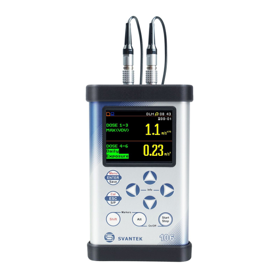
Page 94: Calculation Of Hand-Arm And Whole-Body Daily Results - Calculator
SV106 user's manual The dosimeter presentation mode is always active when Dosimeter switched on. Fields description of the dosimeter view 1. Channels used for dose calculation. In case SV 105AF is used, also FORCE 1-3/4-6 may be available here. 2. Function name which may include: Daily Exposure, Vector, MAX(VDV), Currrent Exposure, AEQ,... - Page 95 SV106 user's manual The Invalid File Content message is displayed when the selected file does not contain dosimeter data. The instrument waits for the reaction of the user by pressing any push-button except <Shift> and <Alt>. After that, it returns to the Selected Files list.
- Page 96 SV106 user's manual Add Additional Files To add additional files the user should press the <ENTER> push-button on this position, select the new files and press <ENTER> again. <ENT> Replace All Files To replace all files the user should press <ENTER>...
- Page 97 SV106 user's manual Whole-Body daily dose results The HA WB Daily Results position is used display daily dose calculations for all selected files. <ENT> Hand-Arm partial results The HA Partial Results position is used to display daily HA dose results for all selected files.
Need help?
Do you have a question about the SV 106 and is the answer not in the manual?
Questions and answers