Table of Contents
Advertisement
SV 104 USER'S MANUAL_
I I I I n n n n str stru stru stru u ment
menta a tion for Science
menta
menta
tion for Science a a n n n n d d d d I I I I n n n n d d d d u u u u s s s s try try try try
tion for Science a
tion for Science a
DRAFT
_______________________________________________
SV 104
ACOUSTIC DOSIMETER
USER'S MANUAL
SVANTEK Sp. z o.o.
WARSAW, July 2013
ISI sa-nv Rue du Doyenné 3 - 1180 Brussels Tel +32 (0) 2 343 30 81 Fax 02/ 343 12 05 web : http://
_
1
www.isi-be.com mail : sales@isi-be.com
Advertisement
Table of Contents

Related Manuals for Svantek SV 104


Summary of Contents for Svantek SV 104
- Page 1 DRAFT SV 104 USER'S MANUAL_ _______________________________________________ SV 104 ACOUSTIC DOSIMETER USER’S MANUAL SVANTEK Sp. z o.o. WARSAW, July 2013 I I I I n n n n str stru stru stru u ment menta menta menta a tion for Science...
- Page 2 Copyright © 2013, SVANTEK sp. z o.o. All rights reserved. No part of this publication may be reproduced or distributed in any form, or by any means, without prior written consent from SVANTEK, Warsaw, Poland Thank you for buying and using this SVANTEK product!
-
Page 3: Table Of Contents
_______________________________________________ CONTENTS INTRODUCTION Sound pressure Dosimetry Standards Applications Measurement procedures KIT COMPONENTS SV 104 dosimeter short form specification Accessories included Accessories available Instrument Software (Firmware) options available GETTING STARTED System description Input output interfaces description The windshield The mounting clips... - Page 4 Before and after measurement run 4.10 Starting and stopping measurement run 4.11 Auto-run mode information 4.12 Security lock 4.13 Mounting and positioning the SV 104 4.14 Reviewing measurements 4.15 Resetting the dosimeter SUPERVISOR BASIC OPERATIONS Installing and connecting to PC Main software window...
- Page 5 DRAFT SV 104 USER'S MANUAL_ _______________________________________________ SVANTEK SERVICE...
- Page 6 DRAFT SV 104 USER'S MANUAL_ _______________________________________________ LIST OF FIGURES 2-1 SV 104 ..................13 IGURE INSTRUMENT WITH THE MICROPHONE AND WINDSHIELD 3-1 SV 104 ............................. 15 IGURE AT A GLANCE 3-2 SV 104 – .................. 16 IGURE SIDE VIEW MICROPHONE AND MICRO...
- Page 7 DRAFT SV 104 USER'S MANUAL_ _______________________________________________ 5-21 L “D ” - ....................58 IGURE OCAL FILES ROWSER WINDOW LAYOUT 5-22 SUPERVISOR SESSION ....................... 59 IGURE MAIN WINDOW 5-23 SESSION .......................... 60 IGURE CONFIGURATION PANEL 5-24 M SUPERVISOR ......................61 IGURE...
-
Page 8: Introduction
“Never before has a noise dosimeter been so accomplished yet so affordable, making your measurements more accurate and reliable than ever before”. To get started quickly with the SV 104, the first part of the manual describes basic noise dosimetry information followed by a guide to setting up the dosimeter and running measurements. -
Page 9: Sound Pressure
DRAFT SV 104 USER'S MANUAL_ _______________________________________________ Sound pressure The human ear responds to audible sound pressure levels in the range from 20 μPa (hearing threshold) to 20 Pa (pain threshold), resulting in the enormous scale 1:10,000,000. Since using such a large arithmetic scale is not practical, a logarithmic scale in decibels (dB) was introduced which is also in agreement with physiological and psychological hearing sensations. -
Page 10: Standards
DRAFT SV 104 USER'S MANUAL_ _______________________________________________ Standards The effects of high sound exposure on hearing have been studied for many years. As far back in 1954 AIHA (American Industrial Hygiene Association) – Rosenwinkel & Stewart – described a “new device which integrates sound energy over finite time periods.”... -
Page 11: Applications
This makes checking for different regulatory bodies’ compliance and ensuring if hearing conservation programs are needed definitely easier than ever before. The SV 104 answers all the important questions such as WHEN? and HOW? did the noise exposure appear? The data logging measurements can be started immediately or they can be pre-programmed in advance so that measurement run can begin and end automatically at a preset start and end time without the need for any onsite supervision. -
Page 12: Measurement Procedures
DRAFT SV 104 USER'S MANUAL_ _______________________________________________ Measurement procedures Preferably, when taking measurements, the noise dosimeter should be attached to the employee at the start of a shift and collected at the end of the whole shift. In case a shorter period is sampled then care should be taken to ensure that the result is representative of the full shift exposure. -
Page 13: Kit Components
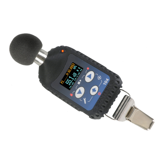
Automatic acoustic field calibration with one touch activation before and after measurement Operational time > 40 hours (display off, octave analysis off) Extremely compact, light weight and robust case with IP65 ingress protection Figure 2-1 SV 104 instrument with the microphone and windshield... -
Page 14: Accessories Included
SA 54 – Charger/power supply for 1 x SV 104 SA 73 - Carrying case for 5 x SV 104 dosimeters and accessories (waterproof) SA 156 – USB HUB for charging and data download from 5 x SV104 dosimeters ... -
Page 15: Getting Started
DRAFT SV 104 USER'S MANUAL_ _______________________________________________ GETTING STARTED System description The following Figure 3-1 shows the SV 104 controls and ports: SV 27 microphone with SA 122 windshield LED status indicator AMBER: stop mode GREEN: measuring RED:... -
Page 16: Input Output Interfaces Description
(reserved for future use) microphone mounting head micro USB connector SV 104 side view – microphone and micro USB connector Figure 3-2 charging infrared connector port Figure 3-3 SV 104 back view - charging and infrared port (reserved for future use) -
Page 17: The Windshield
Figure 3-4 SA 122 windshield The mounting clips Upon delivery, the SV 104 will be fitted with the standard mounting clips. Mounting clips can be easily changed using just hand force. Figure 3-5 SV 104 standard mounting clips... -
Page 18: Led Status Indicator
DRAFT SV 104 USER'S MANUAL_ _______________________________________________ LED status indicator There is a three-colour instrument LED status indicator on the SV 104, located to the right of the microphone mounting head and above the display. Table 3-1 explains conditions under which the specific LED colour appears. -
Page 19: Manual Control Of The Instrument
SCROLL thru the results with the <SCROLL> Notice: To save power consumption and extend battery life SV 104 will automatically switch off the display after 30 seconds if no button on the keypad is pressed. The LED indicator will still inform the user about the current state of operation and any possible alarm conditions. -
Page 20: Primary Key Functions
DRAFT SV 104 USER'S MANUAL_ _______________________________________________ 3.7.1 Primary key functions On the front panel of the instrument the following control push-buttons are located. See below for primary (short press) key functions description: ACOUSTIC PROFILE number and status bar RESULTS <SCROLL> key <PROFILE>... -
Page 21: Alternate Key Functions
3… 2… 1… for the <SCROLL> Keyboard lock Voice comment 3… 2… 1… for the <PROFILE> If you release the key too early, SV 104 returns to the last used VIEW mode and the selected control is not executed. -
Page 22: Alternate Combined Keys Function
DRAFT SV 104 USER'S MANUAL_ _______________________________________________ 3.7.3 Alternate combined keys function Additionally, combined short press of two keys simultaneously (keypad icons marked with white colour) allow quick access to even more functionalities. <SCROLL> <PROFILE> & START/STOP MEASUREMENT RUN <PROFILE> <ENTER>... -
Page 23: Three Instruments In One - Acoustic Profile Concept
Three instruments in one – ACOUSTIC PROFILE concept SV 104 is able to monitor and log noise by enabling up to three different parameter configuration settings, also referred to as “ACOUSTIC PROFILE”. One can set profile no 1 to run measurements using the... -
Page 24: Primary "One-Result" Parameters View Mode
DRAFT SV 104 USER'S MANUAL_ _______________________________________________ Primary “ONE-RESULT” parameters view mode 3.9.2 The one result mode is always available in all measurement modes, and cannot be disabled. In one result mode any measurement result, selected via <SCROLL> , may be presented. The user may change the actual profile view by pressing <PROFILE>... -
Page 25: Octave Analysis Spectrum View Mode
DRAFT SV 104 USER'S MANUAL_ _______________________________________________ 3.9.4 OCTAVE analysis spectrum view mode The instrument operates as a real time 1/1 octave band analyser (RTA). In addition and if enabled, 1/1 octave analysis is performed in parallel with the dose meter operations. All 1/1-octave digital pass-band filters (with 9 centre frequencies from 8 kHz down to 31.5 Hz;... -
Page 26: Instrument Status View Mode
Apart from simple LED alarm indications (see chapter 3.5) there are a few alarm conditions, when ALARM presentation screens will appear. During a measurement run the SV 104 will immediately turn on the display at the time that the programmable alarm condition is exceeded. The detailed alarm state condition for each profile is presented to the user. -
Page 27: Running And Operating Basic Procedures
USB port or optionally provided charger (SA 54). Ensure the SV 104 is fully charged prior to use by connecting it to a USB port or to USB charger. Ensure the power supply is connected and the supply is switched on. The SV 104 will automatically switch on during charging and display how much charge is within the instrument. -
Page 28: Before You Turn The Instrument On
30 seconds, and the unit will turn off after approximately 5 minutes of no keypad activity to save the batteries. Notice: SV 104 will show a warning screen if the battery capacity is below 2 hours of potential measurement time. -
Page 29: Figure 4-1 Power-Off Warning Screen
(“Shutting down” 3… 2… 1… ) is displayed. Thus, the SV 104 gives you time to decide if you really want to turn off the instrument. If you release the key too early, the SV 104 returns to the last presented VIEW mode. -
Page 30: Battery Check
DRAFT SV 104 USER'S MANUAL_ _______________________________________________ Battery check Observe the battery icon in the instrument’s icon status bar or press the <ENTER> key until the Instrument Status VIEW mode is presented and check the battery state. If it is too low, charge the batteries (chapter 4.1). -
Page 31: Reviewing Unit Label
Unit label screen is moved with <SCROLL> , <PROFILE> keys. To exit the Unit Label screen just short press the <ENTER> key. Then SV 104 will return to the last presented VIEW mode. Notice: The personalized Unit Name can be set arbitrarily with SUPERVISOR software. -
Page 32: Measurement Setups - Basic Configuration
DRAFT SV 104 USER'S MANUAL_ _______________________________________________ Measurement Setups - basic configuration at the same time. The “Load Setup” menu Press two keys <SCROLL> and <ENTER> will appear with the list of loaded configuration setups to choose. Figure 4-4 Load setup menu To abandon setup selection, press again the <SCROLL>... -
Page 33: Calibration
_______________________________________________ CALIBRATION The SV 104 dosimeter is offered with the dedicated SV 27 MEMS microphone with ½” housing. It makes the calibration very easy by direct usage of commonly available acoustic calibrators with a ½” cavity. The instrument is factory calibrated with the supplied microphone for the standard environmental conditions. -
Page 34: Figure 4-8 Calibration - Initial Delay Screen
DRAFT SV 104 USER'S MANUAL_ _______________________________________________ 3. Switch on the calibrator and wait ca 30 seconds for the tone to stabilise before starting the calibration measurement 4. Start the calibration measurement by pressing the <ENTER> 5. The calibration measurement time is set to 1 second with 3 seconds delay and stops until the same result is obtained 3 consecutive times. -
Page 35: Figure 4-11 Calibration - Microphone Not In Tolerance Screen
9. Post calibration. If enabled, the post processing is performed automatically under acceptance of calibration measurement. Notice: If it is required to perform so called post-calibration of the instrument. In case the Post Calibration is pre-programmed within configuration setup the SV 104 automatically adds the results to the previously saved files. -
Page 36: Voice Comments Recording
(“Voice comment” 3… 2… 1… ) is displayed. Thus the SV 104 gives you time to decide if you really want to record a voice comment. In case you release the key too early, SV 104 returns to the last used VIEW mode. -
Page 37: Before And After Measurement Run
(see chapter 4.4) select the required configuration setup (see chapter 4.6) the SV 104 is calibrated, because it affects the results (see chapter 4.7) the windshield is put on because it protects the microphone from industrial environment such as dust and moisture or from effects of impact (see chapter 3.3) After stopping the measurement run, make sure: the calibration is still maintained (see chapter 4.7) -
Page 38: Security Lock
(“Keyboard lock” 3… 2… 1… ) is displayed and the unit gives you time to decide if you really want to activate security lock. If you release the key too early, SV 104 returns to the last presented VIEW mode. -
Page 39: Reviewing Measurements
DRAFT SV 104 USER'S MANUAL_ _______________________________________________ 4.14 Reviewing measurements Most of the parameters can be inspected in real-time during either measurement run or stopped mode of operation. If the display screen is turned off just press any key (but watch notice below). -
Page 40: Supervisor Basic Operations
Plug the opposite end of the cable (micro USB) into the dosimeter itself The SV 104 is powered and charged directly through the computer; thus, you do not need separate charger. The dosimeter screen will be switched on automatically with current charging information only ... -
Page 41: Main Software Window
Control panel enables you to select: Instrument control, Data browser or Session you work with Instrument filter enables SV 104 device selection, or other Health and Safety dedicated instruments Inventory panel detects all SV 104 connected devices (see chapter 5.3) ... -
Page 42: Instruments Inventory Panel
_______________________________________________ Instruments inventory panel Click the SV 104 big instrument icon in the left “Instrument filter” Panel (see Figure 5-2) to get access to the devices. Inventory panel (Figure 5-3) enables you to see all currently connected, or previously connected instruments of the same type. -
Page 43: Advanced Configuration Setup
DRAFT SV 104 USER'S MANUAL_ _______________________________________________ Advanced configuration setup Customizing and saving set-ups are performed via the Supervisor. The following sections discuss each of the setup screens and explain how to save and send the parameters to the multiple dosimeter(s). -
Page 44: Figure 5-5 Exporting The Configuration Setup File
SV 104 USER'S MANUAL_ _______________________________________________ For example: To download current settings file from the SV 104, modify it, save with custom name, send it back to the device, export the setup to USB flash memory, and make sure the uploaded settings... -
Page 45: Figure 5-6 Instrument Files Panel And Context Commands
DRAFT SV 104 USER'S MANUAL_ _______________________________________________ 9. Now it is time to upload the configuration back to the instrument. Just click the left arrow pictogram. 10. Once copied select the copied file in the Instrument files, and right click onto it to open context menu. -
Page 46: Profile Settings Tab
DRAFT SV 104 USER'S MANUAL_ _______________________________________________ 5.4.2 Profile settings tab The main settings where specific acoustic profile configuration can be set are located under “Dosimeter” tab. There are already predefined presets in each profile column. By choosing predefined configuration some obvious fields will be automatically greyed. Others must be setup by the user. -
Page 47: Measurement Parameters Settings Tab
5.4.3 Measurement parameters settings tab Within the measurement tab you can choose in which mode of operation the SV 104 should work: Dosimeter, or Dosimeter with 1/1 octave analysis. Notice: Enabling octave analysis shortens battery life, so take it into consideration and double check the battery status before measurement run. -
Page 48: Time-History Data Logging Settings Tab
DRAFT SV 104 USER'S MANUAL_ _______________________________________________ 5.4.4 Time-history data logging settings tab To enable logging time-history data go to the “Time History” settings tab and switch the very first switch button on the left panel. In the left panel named “Time History Setup” there are basic configuration fields related to: how frequently do you want to log the parameters, what name the logger file should have, and if extended summary results should be saved. -
Page 49: Display View Configuration Tab
In the right panel named “Display Results”, you will find a list of over a dozen measurement parameters, that can be configured to be presented on the SV 104 display, when you press <SCROLL> key. See Appendix D to review acronyms for each parameter. -
Page 50: Octave Analysis Spectrum Configuration Tab
DRAFT SV 104 USER'S MANUAL_ _______________________________________________ 5.4.6 Octave analysis Spectrum configuration tab Real time 1/1 octave analysis is an additional optional feature. Therefore it has its own settings tab. Within this tab there are the following panels: named “Data”: This configures the weighting filter that is to be used with octave calculation. -
Page 51: Calibration Settings Panel
DRAFT SV 104 USER'S MANUAL_ _______________________________________________ 5.4.7.1 Calibration settings panel Sometimes it is required to perform so called post-calibration of the instrument. The position Post Cal. enables the user to perform additional calibration after a measurement session and add the results to the file saved in the memory. -
Page 52: Security Settings Panel
See the chapter 4.12 how to lock, and unlock the SV 104 instrument. If “Unlock on Key” is set to On, SV 104 will require special code to be input by pressing four keys defined in this panel in a particular sequence If “Unlock on Key”... -
Page 53: Auxiliary Settings Panel
DRAFT SV 104 USER'S MANUAL_ _______________________________________________ 5.4.7.4 Auxiliary settings panel Under auxiliary settings panel it is possible to: Enable additional warning screens to be displayed under certain conditions: “Logging disabled” it warns the operator that time history results will not be stored. -
Page 54: Auto-Run Settings (Timer, Pauses) Tab
DRAFT SV 104 USER'S MANUAL_ _______________________________________________ 5.4.8 Auto-Run settings (timer, pauses) tab The Timer panel enables the user to program the internal real time clock to act as a delayed start and stop timer. The instrument can be switched on by itself at the pre-selected programmed time and it can then perform the measurement run, which was used before it was last switched off. - Page 55 DRAFT SV 104 USER'S MANUAL_ _______________________________________________ Setting hour and day of the measurement’s start The “Start Time” determines the time for the measurement to start. The required hour and minute can be selected. The “Start Day” determines the date of the measurement start. The timer can be programmed up to one month ahead and during the date setting the current state of the Real Time Clock is taken into account.
-
Page 56: Recording Options Tab
DRAFT SV 104 USER'S MANUAL_ _______________________________________________ 5.4.9 Recording options tab Event and wave recording are mutually exclusive functions and as such you need to turn off the one option in order enable the other one. 5.4.9.1 Event and Wave recording configuration panel Audio Event and Wave Recording may be configured to measure in different “Recording Mode”: See... -
Page 57: Working With Data Files
DRAFT SV 104 USER'S MANUAL_ _______________________________________________ Working with data files 5.5.1 Instrument files If you want to download any recorded files, whatever it is: logger, voice comment, or audio events files, you should click the “Download” button on the control area. -
Page 58: Local Files "Data Browser
DRAFT SV 104 USER'S MANUAL_ _______________________________________________ Local files “Data Browser” 5.5.2 Within the Data Browser tab you can see the list of previously downloaded files ready for further processing. Note that selected files will generate a short preview in the bottom area giving the operator an initial idea of the time history of the measurement results. -
Page 59: Working With Sessions And Reporting
DRAFT SV 104 USER'S MANUAL_ _______________________________________________ Working with sessions and reporting One of the main advantages of the SUPERVISOR is its incredibly simple but professional and user customizable report creation. Once you get familiar with the power of document design you will love it and probably never come back to the old fashioned way of reporting. - Page 60 DRAFT SV 104 USER'S MANUAL_ _______________________________________________ SESSION configuration panel enables you to see the currently selected measurement data in the “Session data” sub-panel. double click to add panel to the report “Add panel” contains a list of available information sections or chunks so called panels that are available to place in the report.
-
Page 61: Report Panels
DRAFT SV 104 USER'S MANUAL_ _______________________________________________ Figure 5-24 Managing templates with SUPERVISOR 5.6.1 Report panels See the following panels, then configure, and generate report. Report options: With “Report options” window it is very straightforward to edit basic report information and predefined graphics, colour and style. -
Page 62: Figure 5-26 Hearing Protectors (Hml) Panel
DRAFT SV 104 USER'S MANUAL_ _______________________________________________ Figure 5-26 Hearing protectors (HML) panel Figure 5-27 Instrument configuration panel... -
Page 63: Figure 5-28 Logger 1/1 Octave Panel
DRAFT SV 104 USER'S MANUAL_ _______________________________________________ Figure 5-28 Logger 1/1 Octave panel Figure 5-29 Logger 1/1 Octave TSect panel Figure 5-30 Logger combined panel... -
Page 64: Figure 5-31 Logger Results Panel
DRAFT SV 104 USER'S MANUAL_ _______________________________________________ Figure 5-31 Logger results panel Figure 5-32 Logger Statistics panel... -
Page 65: Figure 5-33 Marked Periods Totals Panel
DRAFT SV 104 USER'S MANUAL_ _______________________________________________ Figure 5-33 Marked periods Totals panel Figure 5-34 Noise exposure (ISO 9612) panels... -
Page 66: Figure 5-35 Session Header Panel
DRAFT SV 104 USER'S MANUAL_ _______________________________________________ Figure 5-35 Session header panel Figure 5-36 Configurable Text panel Powerfull “What if” panel Figure 5-37... -
Page 67: Sv104 Maintenance
Cleaning Few things to remember: Every time the SV 104 gets too dirty, clean the surface of the dosimeter with damp soft cloth. Pay special attention that the provided SA 122 windshield is clean because dirtiness can affect the measurements. Take off the windshield, shake off any dirt, and clean it with damp cloth. -
Page 68: Changing The Microphone And Windshield
Be gently and be aware not to break or strip the thread. Notice: Note, When the microphone is changed, the new microphone serial number should be programmed into the SV 104 internal memory. It can be easily programmed thru the freely provided SUPERVISOR software. -
Page 69: Transportation And Carrying
DRAFT SV 104 USER'S MANUAL_ _______________________________________________ Transportation and carrying For transportation or storage purpose, always use the packaging provided by the manufacturer. In a potentially dirty industrial environment it is advisable to use the carrying case provided by the manufacturer such as the SA 73 (see chapter 2.3), which ensures excellent mechanical and environmental protection and... - Page 70 SVANTEK SERVICE Should your SVANTEK professional measurement equipment need to be returned for repair or for calibration, please contact the service office at the following number or contact via the SVANTEK’s website. Service Office: +48 (22) 51-88-320 or +48 (22) 51-88-322.
- Page 71 DRAFT SV 104 USER'S MANUAL_ _______________________________________________ INDEX Accessories available · 14 Measurement procedures · 12 Accessories included · 14 Measurement setups · 32 Applications · 11 Mounting · 38 Mounting clips · 17 Basic configuration · 32 Battery check · 30 Periodic testing ·...
Need help?
Do you have a question about the SV 104 and is the answer not in the manual?
Questions and answers