Table of Contents
Advertisement
Quick Links
This manual has been provided to assist
you with lift installation and operation.
For further assistance please contact
your authorized Harmar dealer or
Harmar's Technical Service department.
Tel: 866-378-6648
Fax: 816-537-0641
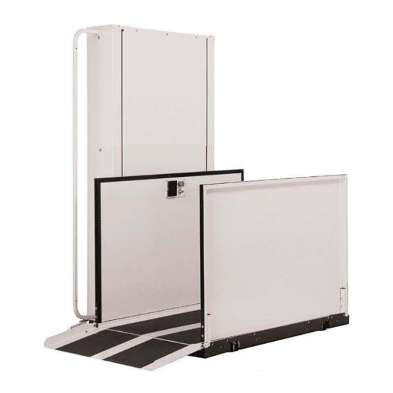
H I G H L A N D E R
Commercial Platform Lift
CPL400
CPL600
CPL800
CPL1000
CPL1200
CPL1400
CPLP400
TG400
P/N: 630-00042 Rev D
Advertisement
Table of Contents

Related Manuals for Harmar Mobility CPLP400


Summary of Contents for Harmar Mobility CPLP400
- Page 1 H I G H L A N D E R Commercial Platform Lift CPL400 CPL600 CPL800 CPL1000 CPL1200 CPL1400 CPLP400 TG400 This manual has been provided to assist you with lift installation and operation. For further assistance please contact your authorized Harmar dealer or Harmar’s Technical Service department. Tel: 866-378-6648...
-
Page 2: Table Of Contents
Table of Contents Installing the lift Using the Manual When You Receive the Lift Specifications Safety Code Requirements Site Requirements Required Tools Required Materials Preparing to Install the Lift Controller Harness Connections Installing the platform Installing the outer guard panel Installing the fixed ramp Installing the folding ramp Anchoring the Lift... -
Page 3: When You Receive The Lift
When You Receive the Lift • Check the lift for shipping damage. If you see any damage contact the freight carrier to file a damage claim. • Verify the products match that described on the packing list attached to the exterior packaging. •... -
Page 4: Code Requirements
Code Requirements Your lift has been designed to meet ASME A18.1 section 2 and CSA B44/ASME A17.5, with the addition of certain options. Code requirements for Vertical Platform lifts vary depending on location. It is the installers responsibility to contact their local code enforcement office and determine all of the regulations they are subject to. -
Page 5: Preparing To Install The Lift
Preparing to Install the Lift Final Site Inspection Verify the surface the lift will mount to is smooth and level. This surface must be made from 3,500 psi reinforced concrete with a minimum thickness of 4”. Verify that there is enough space for the lifts foot print. Be sure to include space neccesary for platform. Caution: Verify that the running clearance around the lift complies with any codes for your area. -
Page 6: Installing The Platform
Installing the Platform Step 1 Step 3 The mounting bolts, nuts and spacers that Align the four mounting holes with those on secure the platform to the lift carriage are the carriage. Insert 1/2 x 3” hex head bolts into packaged in the small parts box. -
Page 7: Installing The Outer Guard Panel
Installing the Platform Guard Panels Step 1 Step 3 Insert the guard panel posts in the pockets in Plug in the harness for the platform control the platform. The smooth side of the guard panel box. Secure the harnesses under the clip on faces toward the center of the platform. -
Page 8: Installing The Folding Ramp
Installing Auto-folding Ramp (optional) Step 1 Step 3 Install the ramp roller guide on the side of the Attach the ramp to the pivot tabs using lift tower using the screws already installed in shoulder bolts and locking nuts. Tighten the the panels. -
Page 9: Anchoring The Lift
Anchoring the Lift Step 4 (800 or taller models) Taller lifts must have the top of the lift Anchors tower anchored into a solid surface to Harmar recommends securing the lift using ensure running clearances remain the concrete anchors provided. If you constant. -
Page 10: Setting The Limit Switches
Setting the Limit Switches Your lift is equipped with upper and lower limit switches. The vertical location of these switches may be adjusted to fit your application. Typically the upper limit switch will need to be adjusted so the platform will stop level with the upper landing. -
Page 11: Verifying Operation Of The Lift
Verifying Operation of the Lift Caution: Complete the following section before training the customer to use the lift. Step 1 Run the lift up and down for 5 complete cycles. Hold the direction button down and allow the limit switches to stop the lift. At the top, verify that the platform stops level with the upper landing. At the bottom, verify the access ramp (if equipped) unfolds and rests on the ground. -
Page 12: Manual Override
Manual Override Call-Sends (optional) Your lift is equipped with a manual The optional Call-Send controls are to be handcrank, to be used in the case of a power used at the upper and/or lower landings to failure. call the platform to you or send it to the other landing. -
Page 13: Top Landing Gate (Optional)
Top Landing Gate (optional) A length of multi‐conductor wire will The optional top landing gate is provided with a combination need to be ran from the bottom of the lift mechanical lock and electric contact (interlock). tower up to the landing gate. Consult local codes for type and mounting The interlock: requirements. After wiring is completed, • Prevents the lift from running if the gate is not closed. the wiring harness must be plugged into •... -
Page 14: Emi And Flush Strike (Optional)
EMI and Flush Strike Interlocks (optional) The optional EMI or Flush Strike Interlocks are provided with a combination mechanical lock and electric EMI Interlock contact. They are to be used with existing doors. The interlock: • Prevents the lift from running if the door is not closed. -
Page 15: Platform Gate (Optional)
Platform Gate (optional) The optional platform gate is provided with a combination mechanical lock and electric contact (interlock). The interlock: • Prevents the lift from running if the gate is not closed. • Prevents the gate from being opened if the platform is not at the bottom landing. •... -
Page 16: Fascia Panel (Optional)
Fascia Panel (optional) A fascia panel provides a smooth surface for the platform edge to run against to prevent any shear or obstruction hazards and must be utilized. A running clearance of no more than 3/4” and no less than 3/8” must be maintained between the edge of the platform and the fascia panel. -
Page 17: Alarm (Optional)
Platform Control with Optional E-Stop Alarm If equipped, the e-stop button on the platform lights up and sounds an alarm when pressed. You will need to obtain a 6 volt lantern battery like the example below. The battery can sit under the top cap to the right of the motor pulley. There is a wire harness for the battery located here. -
Page 18: Owner's Section
Commercial Platform Lift - Owners Section Read the manual thoroughly before operating the lift. -
Page 19: Safety
Congratulations on the purchase of your Harmar Vertical Platform Lift. This lift has been engineered to provide trouble free service for many, many years. Please read this manual completely before operating your lift. Safety • Do not exceed the maximum payload capacity of 750 lbs. •... -
Page 20: Controls
Controls Emergency Stop In an emergency push this red button to stop the lift. Turn the button clockwise to run. Controls upward movement of lift platform. To move platform up, depress and hold the upper half of the rocker switch. To cease movement, release switch. -
Page 21: Operating The Lift
Operating the Lift Step 1 - Up Step 3 Drive onto and stop in the middle of the Press and hold the UP rocker. The lift will platform. Apply the brakes of your chair or move in the up direction and stop when it scooter. - Page 22 Step 1 - Down Step 3 Drive onto and stop in the middle of the Press and hold the DOWN rocker. The lift platform. Apply the brakes of your chair or will move in the down direction and stop scooter. when it reaches the lower landing.
-
Page 30: Warranty
Authorized Harmar Distributor or certified Harmar Installer. EXCEPTIONS TO THIS LIMITED WARRANTY ARE: PLEASE READ CAREFULLY Parts used that are not approved by Harmar Mobility, LLC. • Harmar CPL’s and EPL’s installed outdoors must include the •... - Page 31 NOTES...
- Page 32 Highlander Commercial Platform Lift Installation and Owner's Manual P/N: 630-00042 Rev C...
Need help?
Do you have a question about the CPLP400 and is the answer not in the manual?
Questions and answers