
Related Manuals for SMC Networks CHSD Series


Summary of Contents for SMC Networks CHSD Series
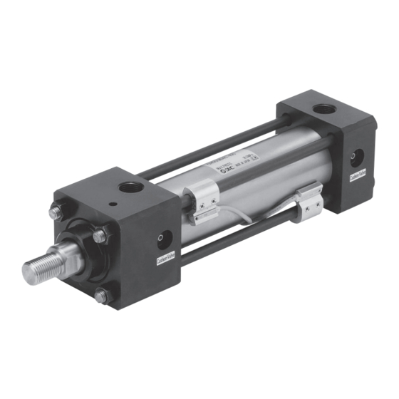
- Page 1 ISO Standard Hydraulic Cylinder CHSD Series 10 MPa Nominal pressure: Bore size [mm]: 40, 50, 63, 80, 100 CHSG Series 16 MPa Nominal pressure: Bore size [mm]: 32, 40, 50, 63, 80, 100 CHSD/CHSG Series EMC-CHSD-CHSG-01A-UK...
- Page 2 ISO Standard Hydraulic Cylinder Series Nominal pressure 10 MPa /16 MPa Reduced projection area: or less Reduced overall length CHSD/Basic Stroke CHSD/CHSG Stroke Overall length (A size) Tube size Maximum weight: no more than [mm] CHSD CHSG ∗ ∗ of CH2 series (CHSD) (CHSG) ∗...
- Page 3 ISO Standard Hydraulic Cylinder CHSD Series 10 MPa Ø 40, Ø 50, Ø 63, Ø 80, Ø 100 How to Order M9BW CH D SD B 40 Magnet for auto switch Number of auto switches — Without Series type — 2 pcs.
- Page 4 CHSD Series Specifications Bore size [mm] Double Acting: Single Rod Action General mineral hydraulic fluid Fluid Nominal pressure 10 MPa 12 MPa Maximum allowable pressure 15 MPa Proof pressure With pressure at front side 0.25 MPa Minimum operating pressure With pressure at rear side 0.15 MPa -10 to 80 °C Without magnet...
- Page 5 ISO Standard Hydraulic Cylinder CHSD Series 10 MPa Construction CH SDB t @4 #1 @0 y i !9 Parts List Description Material Description Material Rod cover Carbon steel Retaining ring Carbon tool steel Head cover Carbon steel Set screw Alloy steel Seal holder Carbon steel Stainless steel...
- Page 6 CHSD Series Dimensions Basic: CHSDB + Stroke + Stroke 2 x Rc Cushion valve Air release + Stroke + Stroke Bore size Stroke [mm] range 25 to 800 M6 x 1 M16 x 1.5 161.5 25 to 800 M8 x 1 M20 x 1.5 46.5 28.5...
- Page 7 ISO Standard Hydraulic Cylinder CHSD Series 10 MPa Rod flange: CHSDFY + Stroke + Stroke 2 x Rc Head side cushion valve Ø FD Air release Rod side Air release air release + Stroke + Stroke Rod side cushion valve Bore size Stroke [mm]...
- Page 8 CHSD Series Dimensions Double clevis: CHSDCB Width across flats + Stroke + Stroke 2 x Rc Cushion valve release + Stroke + Stroke Bore size Stroke [mm] range 25 to 800 M6 x 1 M16 x 1.5 25 to 800 M8 x 1 M20 x 1.5 46.5...
- Page 9 ISO Standard Hydraulic Cylinder CHSD Series 10 MPa Accessory (Option) Rod end nut Material: Carbon steel Bore size Part no. [mm] NTH-040 25.4 M16 x 1.6 NTH-050 31.2 M20 x 1.5 NTH-060S 47.3 M27 x 2 NTH-080S 57.7 M33 x 2 NTH-100S M42 x 2...
- Page 10 CHSD Series Auto Switch Mounting Refer to pages 431 to 490 for detailed specifications. Auto Switch Proper Mounting Position (Detection at Stroke End) and Its Mounting Height D-A5 /A6 D-M9 /M9 V D-F5 (W)/J59(W)/F5BA D-M9 W/M9 WV D-M9 A/M9 AV D-Z7 /Z80 Auto Switch Proper Mounting Position Auto Switch Mounting Height...
-
Page 11: Table Of Contents
CHSD Series Auto Switch Mounting Auto Switch Mounting Brackets: Part Nos. Bore size [mm] Auto switch models Ø 40 Ø 50 Ø 63 Ø 80 Ø 100 D-M9 /M9 V D-M9 W/M9 WV BMB5-032 BA7-040 BA7-040 BA7-063 BS5-125 D-M9 A/M9 AV D-F5 /J59 D-F5 W/J59W BT-03... - Page 12 CHSD Series How to Mount and Move the Auto Switch <Applicable auto switch> <Applicable auto switch> D-M9N(V) D-M9P D-M9B D-Z73, D-Z76, D-Z80 Solid state ······ Reed ······ D-M9NW D-M9PW D-M9BW D-M9NA D-M9PA D-M9BA Watchmaker’s (precision) screwdriver Auto switch Watchmaker’s (precision) Hexagon socket head set screw (M4) mounting screw screwdriver...
- Page 13 CHSD Series Auto Switch Mounting How to Mount and Move the Auto Switch <Applicable auto switch> D-F59, D-F5P Solid state ······ D-J59, D-F5BA D-F59W, D-F5PW, D-J59W D-F59F, D-F5NT D-A53, D-A54, D-A56, D-A64, D-A67 Reed ··············· D-A59W Auto switch mounting screw (M4) Auto switch Auto switch mounting bracket Set screw (M4)
- Page 14 ISO Standard Hydraulic Cylinder CHSG Series 16 MPa Ø 32, Ø 40, Ø 50, Ø 63, Ø 80, Ø 100 How to Order M9BW CH D SG B 40 Magnet for auto switch Number of auto — Series type Without switches Built-in Symbol...
- Page 15 ISO Standard Hydraulic Cylinder CHSG Series 16 MPa Specifications Bore size [mm] Double Acting: Single Rod Action Fluid General mineral hydraulic fluid Nominal pressure 16 MPa 20 MPa Maximum allowable pressure Proof pressure 24 MPa With pressure at rod side 0.25 MPa Minimum operating pressure...
- Page 16 CHSG Series Construction CH SGB @1 @3 @2 e !8 @7 #0 !7 #1 t @4 @5 #2 @0 y i !9 Parts List Description Material Description Material Rod cover Carbon steel Retaining ring Carbon tool steel Head cover Carbon steel Set screw Alloy steel Seal holder...
- Page 17 ISO Standard Hydraulic Cylinder CHSG Series 16 MPa Dimensions Basic: CHSGB + Stroke + Stroke 2 x Rc Air release Cushion valve + Stroke + Stroke Bore size Stroke [mm] range 25 to 800 33.2 M6 x 1 M14 x 1.5 153.5 25 to 800 41.7...
- Page 18 CHSG Series Dimensions Rod flange: CHSGFY + Stroke Head side cushion valve + Stroke Ø FD 2 x Rc Air release release Rod side air release + Stroke + Stroke Rod side cushion valve Bore size Stroke [mm] range 25 to 800 33.2 M6 x 1 M14 x 1.5...
- Page 19 ISO Standard Hydraulic Cylinder CHSG Series 16 MPa Single clevis: CHSGCA + Stroke + Stroke 2 x Rc Ø CD Cushion valve Width across flats Air release Air release + Stroke + Stroke Bore size Stroke [mm] range 25 to 800 33.2 M6 x 1 M14 x 1.5...
- Page 20 CHSG Series Dimensions Rod trunnion: CHSGTA + Stroke Width across flats + Stroke Head side cushion valve 2 x Rc Air release Rod side cushion Rod side air valve release + Stroke + Stroke Bore size Stroke [mm] range 25 to 800 33.2 M6 x 1 M14 x 1.5...
- Page 21 ISO Standed Hydraulic Cylinder CHSG Series 16 MPa Accessory (Option) Rod end nut Material: Carbon steel Part no. NTH-32S 25.4 M14 x 1.5 NTH-040 25.4 M16 x 1.6 NTH-050 31.2 M20 x 1.5 NTH-060S 47.3 M27 x 2 NTH-080S 57.7 M33 x 2 NTH-100S M42 x 2...
-
Page 22: D-A5, A6
CHSG Series Auto Switch Mounting Refer to pages 431 to 490 for detailed specifications. Auto Switch Proper Mounting Position (Detection at Stroke End) and Its Mounting Height D-A5 /A6 D-M9 /M9 V D-F5 (W)/J59(W)/F5BA D-M9 W/M9 WV D-M9 A/M9 AV D-Z7 /Z80 Proper Auto Switch Mounting Position Auto Switch Mounting Height... -
Page 23: D-A5, A6
CHSG Series Auto Switch Mounting Minimum Auto Switch Mounting Stroke Centre trunnion Auto switch Auto switch Mounting bracket other mounting number model than centre trunnion 2 (Different surfaces and same surface), 1 – – – – – – – D-M9 /M9 W 20 + 40 85 + 40 95 + 40... - Page 24 CHSG Series Auto Switch Mounting Brackets: Part Nos. Bore size [mm] Auto switch models Ø 32 Ø 40 Ø 50 Ø 63 Ø 80 Ø 100 D-M9 /M9 V D-M9 W/M9 WV BMB5-032 BA7-040 BA7-080 BA7-080 BS5-160 – D-M9 A/M9 AV D-F5 /J59 D-F5 W/J59W BT-03...
- Page 25 CHSG Series Auto Switch Mounting How to Mount and Move the Auto Switch <Applicable auto switch> <Applicable auto switch> D-M9N(V), D-M9P(V), D-M9B(V) D-Z73, D-Z76, D-Z80 Solid state ······ Reed ······ D-M9NW(V), D-M9PW(V), D-M9BW(V) D-M9NA(V), D-M9PA(V), D-M9BA(V) Watchmaker’s (precision) screwdriver Auto switch Watchmaker’s (precision) Hexagon socket head set screw (M4) mounting screw...
- Page 26 CHSG Series How to Mount and Move the Auto Switch <Applicable auto switch> D-F59, D-F5P Solid state ······ D-J59, D-F5BA D-F59W, D-F5PW, D-J59W D-F59F, D-F5NT D-A53, D-A54, D-A56, D-A64, D-A67 Reed ··············· D-A59W Auto switch mounting screw (M4) Auto switch Auto switch mounting bracket Set screw (M4) Tie-rod...
- Page 27 Series Model Selection 1 Cylinder Cushion Selection Selection Procedures Caution Use a cylinder cushion within the maximum absorbed energy range. When used outside the allowable range, it may cause damage to cylinders and peripheral devices. Find the inertial energy for the load at the cushion seal contact point.
- Page 28 Series Model Selection 2 Maximum Absorbed Energy & External Force and Energy Conversion at Cushion Seal Contact Point Maximum absorbed energy pressure and chart in terms of cushion performance characteristics Be sure to keep the combined values of kinetic energy of the load operated by the cylinder and the energy generated by the external force within the values that are shown in the bottom chart.
- Page 29 Series Hydraulic Cylinder Precautions 1 Be sure to read before handling. Selection Warning Warning The products featured in this catalogue are designed strictly for use in industrial oil hydraulic system applications. If the products ery are twisted due to external forces, etc. are used in conditions that are outside the range of pressure In such cases, human injury may occur;...
- Page 30 Series Hydraulic Cylinder Precautions 2 Be sure to read before handling. Selection Cushion Caution cylinders. Provide intermediate supports for cylinders with long strokes to prevent piston rod damage due to sagging of the piston rod, Cushion needles are adjusted at the time of shipment. When deflection of the tube, vibration, and external loads.
- Page 31 Series Hydraulic Cylinder Precautions 3 Be sure to read before handling. Maintenance Warning If handled improperly, malfunction and damage of machinery or equipment may occur. When machinery is removed, first ensure that there are measures in place to prevent the fall or sudden, erratic move- ment of driven objects and equipment.
- Page 32 Series Auto Switch Precautions 1 Be sure to read before handling. Design and Selection Warning although an auto switch may operate normally, the load Read the specifications carefully and use this product appro- may not operate. Therefore, the formula below should be priately.
- Page 33 Series Auto Switch Precautions 2 Be sure to read before handling. Wiring Warning Warning Do not drop, bump, or apply excessive impacts (300 m/s <Reed switches> more for reed switches and 1000 m/s or more for solid state If the power is turned on with a load in a short circuited condi- switches) while handling.
- Page 34 Series Auto Switch Precautions 3 Be sure to read before handling. Maintenance Warning Warning The construction of auto switches is not intended to prevent explosion. Never use in an atmosphere with an explosive gas since this may cause a serious explosion. 1) Securely tighten switch mounting screws.
- Page 35 These safety instructions are intended to prevent hazardous situations and/or equipment Safety Instructions damage. These instructions indicate the level of potential hazard with the labels of “Caution,” “Warning” or “Danger.” They are all important notes for safety and must be followed in addition to International Standards (ISO/IEC) , and other safety regulations.
- Page 36 SMC Corporation (Europe) +43 (0)2262622800 www.smc.at offi ce@smc.at +370 5 2308118 www.smclt.lt info@smclt.lt Austria Lithuania +32 (0)33551464 www.smc.be info@smc.be Netherlands +31 (0)205318888 www.smc.nl info@smc.nl Belgium +359 (0)2807670 www.smc.bg offi ce@smc.bg +47 67129020 www.smc-norge.no post@smc-norge.no Bulgaria Norway +385 (0)13707288 www.smc.hr offi ce@smc.hr +48 222119600 www.smc.pl offi...
Need help?
Do you have a question about the CHSD Series and is the answer not in the manual?
Questions and answers