Advertisement
Quick Links
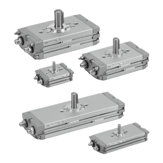
Compact Rotary Actuator
CRQ2
Series
Rack & Pinion Style/Size: 10, 15, 20, 30, 40
Size
Size
17
17
17
10:
10:
10:
20
20
20
15:
15:
15:
29
29
29
20:
20:
20:
33
33
33
30:
30:
30:
37
37
37
40:
40:
40:
Series Variations
Rotating angle
Shaft type
Cushion
Variations
Shaft type
Pattern
Shaft and parallel key stainless steel spec.
∗ For details, refer to our website.
mm
mm
mm
mm
mm
mm
mm
mm
mm
mm
mm
mm
mm
mm
mm
80° to 100°
170° to 190°
350° to 370°
Single shaft
Double shaft
None
Rubber cushion
Air cushion
With auto switch
20 - ∗
Copper-free (Standard)
Single shaft with four chamfers
Double shaft key
Double shaft with four chamfers
Single round shaft
Double shaft (Without long shaft key)
Double round shaft
Shaft end form
Rotating range
Rotation 360° type
10
15
S
W
X
Y
Z
T
J
K
-X6
360°
Size
20
30
40
CRB2
-Z
CRBU2
CRB1
MSU
CRJ
CRA1
-Z
CRA1
CRQ2
CRQ2
MSQ
MSZ
CRQ2X
MSQX
MRQ
Page
P. 272
to
P. 279
P. 280,
P. 281
D-
P. 282
to
P. 296
269
Advertisement

Related Manuals for SMC Networks CRQ2 Series


Summary of Contents for SMC Networks CRQ2 Series
- Page 1 Compact Rotary Actuator CRQ2 Series Rack & Pinion Style/Size: 10, 15, 20, 30, 40 CRB2 Size Size CRBU2 CRB1 CRA1 CRA1 CRQ2 CRQ2 Rotation 360° type 360° CRQ2X MSQX Series Variations Size Page 80° to 100° Rotating angle 170° to 190° 350°...
- Page 3 Compact Rotary Actuator Rack & Pinion Style/Size: 10, 15, 20, 30, 40 Rotary actuator body serves as a flange. CRB2 Built-in cushion CRBU2 10, 15 : Rubber bumper 20, 30, 40 : Air cushion CRB1 360° type 360° Equipped with an angle CRA1 adjusting...
- Page 4 Compact Rotary Actuator Rack & Pinion Style CRQ2 Series How to Order CRQ2B S Without auto switch CDRQ2B S M9BW With auto switch Built-in magnet Number of Shaft type auto switches Single shaft 2 pcs. Double shaft 1 pc. ∗ Refer to pages 280 and n pcs.
-
Page 5: Specifications
Compact Rotary Actuator CRQ2 Series Rack & Pinion Style Specifications Size Air (Non-lube) Fluid 0.7 MPa 1.0 MPa Max. operating pressure CRB2 Min. operating pressure 0.15 MPa 0.1 MPa 0° to 60°C (No freezing) Ambient and fluid temperature CRBU2 Cushion Rubber bumper Not attached, Air cushion Rotation end ±5°... - Page 6 CRQ2 Series Construction Basic style Basic style Size 10/15 Size 20/30/40 !4 !7 !9 !2 !4 !1 @6 @0 @1 @0 !9 !2 !5 i Component Parts Component Parts Description Material Note Description Material Note Body Hexagon socket head set screw Aluminum alloy Anodized Chrome molybdenum steel...
- Page 7 Compact Rotary Actuator CRQ2 Series Rack & Pinion Style Construction With auto switch With auto switch Size 10/15 Size 20/30/40 CRB2 CRBU2 CRB1 CRA1 !4 !7 !9 !2 !4 !1 @6 @0 !9 !2 CRA1 CRQ2 CRQ2 !5 i CRQ2X MSQX With cushion With auto switch and cushion...
- Page 8 CRQ2 Series Dimensions Size 10/15 2 x M5 x 0.8 through (Opposite side 7.6 counterbore depth 4.2) With double shaft ø ø 2 x M5 x 0.8 (Port) ø (AU) Max. (mm) ∗ Size Rotating angle 90°, 180°, 360° 42.4 (8.5) 16.7 90°, 180°, 360°...
- Page 9 Compact Rotary Actuator CRQ2 Series Rack & Pinion Style Dimensions Size 20/30/40 These parts are not attached when a model without air cushion is selected. CRB2 CRBU2 CRB1 through (Opposite side 4 locations) (Opposite side CRA1 counterbore depth With double shaft ø...
- Page 10 CRQ2 Series Rotation Range When pressurized from the port indicated by the arrow, the shaft will rotate in a clockwise direction. Rotating angle: 90° Rotating angle: 180° Key or single flat Key or single flat B port B port A port A port Angle adjustment ±5°...
- Page 11 Compact Rotary Actuator CRQ2 Series Rack & Pinion Style Unit Used as Flange Mount The L dimensions of this unit are shown in the table below. When hexagon socket head cap bolt of the JIS standard is used, the head of the bolt will recess into the groove of actuator.
- Page 12 CRQ2 Series Shaft Type Variation, Four Chamfers (Size 20/30/40) Shaft Type: X, Z Specifications C RQ2B Shaft type Rotating angle Size Air (Non-lube) Fluid CDRQ2B Applicable shaft type Single w/ four chamfers (X), Double w/ four chamfers (Z) 20, 30, 40 Applicable size Refer to “How to Order”...
- Page 13 Compact Rotary Actuator CRQ2 Series Rack & Pinion Style Shaft Type Variation/Without Keyway Shaft Type: T, J, K Specifications C RQ2B Shaft type Rotating angle Size Air (Non-lube) Fluid CDRQ2B Applicable shaft type Single round shaft (T), Double shaft (J), Double round shaft (K) CRB2 Refer to “How to Order”...
- Page 14 CRQ2 Series (Size: 10, 15, 20, 30, 40) Simple Specials: -XA1 to -XA24: Shaft Pattern Sequencing I Shaft pattern sequencing is dealt with a simple made-to-order system. (Refer to front matter 32.) Please contact SMC for a specification sheet when placing an order. Symbol Shaft Pattern Sequencing I -XA1 to XA24...
- Page 15 CRQ2 Series Simple Specials Symbol Shaft Pattern Sequencing I -XA1 to XA8 CRB2 Additional Reminders CRBU2 Symbol: Symbol: Machine female threads into the long shaft. Machine female threads into the short shaft. 1. Enter the dimensions within a range that CRB1 The maximum dimension L1 is, as a rule, twice the thread The maximum dimension L2 is, as a rule, twice the thread...
- Page 16 CRQ2 Series (Size: 10, 15, 20, 30, 40) Simple Specials: -XA1 to -XA24: Shaft Pattern Sequencing I Shaft pattern sequencing is dealt with a simple made-to-order system. (Refer to front matter 32.) Please contact SMC for a specification sheet when placing an order. Shaft Pattern Sequencing I Additional Reminders Symbol:...
- Page 17 CRQ2 Series Simple Specials Symbol -XA9 to XA24 CRB2 CRBU2 Symbol: Symbol: Symbol: Shorten the long shaft. Shorten the short shaft. Both the long shaft and short shaft are shortened. CRB1 • Applicable shaft types: S, W • Applicable shaft type: W •...
- Page 18 CRQ2 Series (Size: 10, 15, 20, 30, 40) Simple Specials: -XA31 to -XA59: Shaft Pattern Sequencing II Shaft pattern sequencing is dealt with a simple made-to-order system. (Refer to front matter 32.) Please contact SMC for a specification sheet when placing an order. Shaft Pattern Sequencing II Applicable shaft type: X, Y, Z, T, J and K How to Order...
- Page 19 CRQ2 Series Simple Specials Symbol -XA31 to XA59 CRB2 Combination Chart of Simple Specials for Tip End Shape CRBU2 Chart 3. Combination between -XA and -XA (X, Y, Z, T, J, K shafts) CRB1 Shaft type Top port Applicable Symbol Description Combination size...
- Page 20 CRQ2 Series (Size: 10, 15, 20, 30, 40) Simple Specials: -XA31 to -XA59: Shaft Pattern Sequencing II Shaft pattern sequencing is dealt with a simple made-to-order system. (Refer to front matter 32.) Please contact SMC for a specification sheet when placing an order. Shaft Pattern Sequencing II Additional Reminders Symbol:...
- Page 21 CRQ2 Series Simple Specials Symbol -XA31 to XA48 CRB2 CRBU2 Symbol: Symbol: Symbol: Shaft with through-hole Shaft with through-hole Shaft with through-hole CRB1 Minimum machining diameter for d1 is 0.1. Minimum machining diameter for d1 is 0.1. Minimum machining diameter for d1 is 0.1. •...
- Page 22 CRQ2 Series Shaft Pattern Sequencing II Symbol: Symbol: Symbol: Shorten the short shaft. Both the long shaft and short shaft are shortened. Shorten the long shaft. • Applicable shaft type: Y • Applicable shaft type: Y • Applicable shaft types: J, K, T Long shaft side Long shaft side Long shaft...
- Page 23 CRQ2 Series Simple Specials Symbol -XA49 to XA59 CRB2 CRBU2 Symbol: Symbol: The rotation axis is reversed, and then shorten the long The rotation axis is reversed, and then shorten the long CRB1 and short shafts. shaft. • Applicable shaft type: J, T •...
- Page 24 CRQ2 Series Made to Order Specifications 1 Please contact SMC for detailed dimensions, specifications and lead times. How to Order RQ2B M9BW X C7 C12 C30 -X6 Built-in magnet Auto switch Symbol for simple specials, Made-to- None Order products Built-in magnet Refer to page 272 for •...
- Page 25 CRQ2 Series Made to Order Specifications Symbol Reversed Shaft -XC7 CRB2 CRBU2 CRQ2B Refer to “How to Order” on page 282 CDRQ2B CRB1 Reversed shaft Specifications Applicable size 10, 15, 20, 30, 40 Applicable shaft type S, W, X, T, J shaft CRA1 CRA1 CRQ2...
- Page 26 CRQ2 Series Made to Order Specifications 2 Please contact SMC for detailed dimensions, specifications and lead times. Symbol -XC8 to XC11, XC18/XC19 Change of Rotating Range CRQ2B Refer to “How to Order” on page 282 X C8 CDRQ2B Specifications Symbol Applicable shaft type S, W, Y -XC8 to XC11, XC18/XC19 Additional Reminders...
- Page 27 CRQ2 Series Made to Order Specifications Symbol Change of Angle Adjustable Range (0° to 100°, 90° to 190°) -XC12 to XC17, XC20/XC21 CRB2 CRBU2 CRQ2B X C12 Symbol: Symbol: Refer to “How to Order” on page 282. CDRQ2B The rotation angle can be adjusted between 0° and 100°. The rotation angle can be adjusted between 0°...
- Page 28 CRQ2 Series Made to Order Specifications 3 Please contact SMC for detailed dimensions, specifications and lead times. Symbol Symbol -XC22 -XC30 Without Inner Rubber Bumper Fluorine Grease C RQ2B C RQ2B XC22 XC30 Refer to “How to Order” on page 282. Refer to “How to Order”...
- Page 29 Low-Speed Rotary Actuator CRQ2X/MSQX Series Possible to transfer a workpiece at low-speed. CRB2 CRBU2 CRB1 Realized a stable motion CRA1 at 5 s/90°. Smooth motion without stick-slip phenomemon CRA1 CRQ2 Speed waveform Speed waveform ( s/90° ) Rotation time adjustment range: Rotation time adjustment range (s/90°) CRQ2X CRQ2X...
-
Page 30: Model Selection
CRQ2X/MSQX Series Model Selection ∗ The selection procedure of the rotary for low-speed is the same as for an ordinary rotary. If the rotation time exceeds 2s per 90°, however, the necessary torque and the kinetic energy are calculated with rotation time of 2s per 90°. Selection Procedure Remarks Selection Example... - Page 31 CRQ2X/MSQX Series Model Selection Ι Equation Table of Moment of Inertia (Calculation of moment of inertia Ι ) m: Load mass (kg) : Moment of inertia (kg·m 1. Thin shaft 6. Thin round plate Position of rotational axis: Position of rotational axis: Perpendicular to the shaft through the center of gravity Passing through the diameter CRB2...
- Page 32 CRQ2X/MSQX Series Load Type Calculation method of necessary torque depends on the load type. Refer to the table below. Load type Static load: Ts Resistance load: Tf Inertial load: Ta Only pressing force is necessary. Weight or friction force is applied to Rotate the load with inertia.
- Page 33 CRQ2X/MSQX Series Model Selection Effective Torque Unit: N ·m CRQ2X MSQX Operating pressure (MPa) Model Size 0.15 — 0.09 0.12 0.18 0.24 0.30 0.36 0.42 — — — CRB2 — 0.22 0.30 0.45 0.60 0.75 0.90 1.04 — — — CRQ2X 0.37 0.55...
-
Page 34: Allowable Load
CRQ2X/MSQX Series Allowable Load CRQ2X A load up to the allowable radial/thrust load can be applied provided that a dynamic load is not generated. However, applications which apply a load directly to the shaft should be avoided whenever possible. In order to further improve the operating conditions, a method such as that shown in the drawing on the right side is recommended so that a direct load is not applied to the shaft. - Page 35 Rotary Actuator Technical Data Air Consumption Air consumption is the volume of air which is expended by the rotary actuator’s reciprocal operation inside the actuator and in the piping between the actuator and the switching valve, etc. This is necessary for selection of a compressor and for calculation of its running cost.
- Page 36 Low-Speed Compact Rotary Actuator Rack & Pinion Style CRQ2X Series Size: 10, 15, 20, 30, 40 How to Order CRQ2 Standard CDRQ2 90 M9BW With auto switch Built-in magnet Low-speed specification Shaft type Single shaft Number of Double shaft auto switches ∗...
- Page 37 Low-Speed Compact Rotary Actuator CRQ2X Series Rack & Pinion Style Specifications Size Air (Non-lube) Fluid 0.7 MPa 1 MPa Max. operating pressure CRB2 Min. operating pressure 0.15 MPa 0.1 MPa 0° to 60°C (No freezing) Ambient and fluid temperature CRBU2 Cushion Not attached Rotation end ±5°...
- Page 38 CRQ2X Series Rotation Range When pressurized from the port indicated by the arrow, the shaft will rotate in a clockwise direction. Rotation angle: 90° Rotation angle: 180° Key or single flat Key or single flat B port B port A port A port Angle adjustment ±5°...
- Page 39 Low-Speed Compact Rotary Actuator CRQ2X Series Rack & Pinion Style Construction Standard Standard Size 10/15 Size 20/30/40 CRB2 CRBU2 CRB1 CRA1 !4 !7 !9 !2 CRA1 CRQ2 CRQ2X CRQ2X MSQX MSQX Component Parts Component Parts Description Material Description Material Body Cross recessed screw No.
- Page 40 CRQ2X Series Construction With auto switch With auto switch Size 10/15 Size 20/30/40 !4 !7 !9 !2...
- Page 41 Low-Speed Compact Rotary Actuator CRQ2X Series Rack & Pinion Style Dimensions Size 10/15 CRB2 CRBU2 CRB1 2 x M5 x 0.8 through (Opposite side 7.6 CRA1 counterbore depth 4.2) CRA1 With double shaft ø ø CRQ2 2 x M5 x 0.8 (Port) CRQ2X CRQ2X...
- Page 42 CRQ2X Series Dimensions Size 20/30/40 through (Opposite side counterbore depth (Opposite side 4 locations) With double shaft ø ø Auto switch 2 x Rc 1/8 ∗∗ (Port) (AU) Max. ø (mm) ∗ Size Rotation angle 90°, 180° (11) 14.5 —...
- Page 43 Low-Speed Compact Rotary Actuator CRQ2X Series Rack & Pinion Style Unit Used as Flange Mount The L dimensions of this unit are shown in the below table. When hexagon socket head cap bolt of the JIS standard is used, the head of the bolt will recess into the groove of actuator.
- Page 44 CRQ2X Series Shaft Type Variation, Four Chamfers (Size 20/30/40) Shaft Type: X, Z Specifications CRQ2XB Shaft type Rotating angle Size Fluid Air (Non-lube) CDRQ2XB Single w/ four chamfers (X), Double w/ four chamfers (Z) Applicable shaft type Applicable size 20, 30, 40 Refer to “How to Order”...
- Page 45 Low-Speed Compact Rotary Actuator CRQ2X Series Rack & Pinion Style Shaft Type Variation/Without Keyway Shaft Type: T, J, K Specifications CRQ2XB Rotating angle Shaft type Size Air (Non-lube) Fluid CDRQ2XB Applicable shaft type Single round shaft (T), Double shaft (J), Double round shaft (K) CRB2 Refer to “How to Order”...
- Page 46 CRQ2X Series (Size: 10, 15, 20, 30, 40) Simple Specials: -XA1 to -XA24: Shaft Pattern Sequencing I Shaft pattern sequencing is dealt with a simple made-to-order system. (Refer to front matter 32.) Please contact SMC for a specification sheet when placing an order. Symbol Shaft Pattern Sequencing I -XA1 to XA24...
- Page 47 CRQ2X Series Simple Specials Symbol Shaft Pattern Sequencing I -XA1 to XA8 CRB2 Additional Reminders CRBU2 Symbol: Symbol: Machine female threads into the long shaft. Machine female threads into the short shaft. 1. Enter the dimensions within a range that CRB1 The maximum dimension L1 is, as a rule, twice the thread The maximum dimension L2 is, as a rule, twice the thread...
- Page 48 CRQ2X Series (Size: 10, 15, 20, 30, 40) Simple Specials: -XA1 to -XA24: Shaft Pattern Sequencing I Shaft pattern sequencing is dealt with a simple made-to-order system. (Refer to front matter 32.) Please contact SMC for a specification sheet when placing an order. Shaft Pattern Sequencing I Additional Reminders Symbol:...
- Page 49 CRQ2X Series Simple Specials Symbol -XA9 to XA24 CRB2 CRBU2 Symbol: Symbol: Symbol: Shorten the long shaft. Shorten the short shaft. Both the long shaft and short shaft are shortened. CRB1 • Applicable shaft types: S, W • Applicable shaft type: W •...
- Page 50 CRQ2X Series (Size: 10, 15, 20, 30, 40) Simple Specials: -XA31 to -XA59: Shaft Pattern Sequencing II Shaft pattern sequencing is dealt with a simple made-to-order system. (Refer to front matter 32.) Please contact SMC for a specification sheet when placing an order. Shaft Pattern Sequencing II Applicable shaft type: X, Y, Z, T, J and K How to Order...
- Page 51 CRQ2X Series Simple Specials Symbol -XA31 to XA59 CRB2 Combination Chart of Simple Specials for Tip End Shape CRBU2 Chart 3. Combination between -XA and -XA (X, Y, Z, T, J, K shafts) CRB1 Shaft type Top port Applicable Symbol Description Combination size...
- Page 52 CRQ2X Series (Size: 10, 15, 20, 30, 40) Simple Specials: -XA31 to -XA59: Shaft Pattern Sequencing II Shaft pattern sequencing is dealt with a simple made-to-order system. (Refer to front matter 32.) Please contact SMC for a specification sheet when placing an order. Shaft Pattern Sequencing II Additional Reminders Symbol:...
- Page 53 CRQ2X Series Simple Specials Symbol -XA31 to XA48 CRB2 CRBU2 Symbol: Symbol: Symbol: Shaft with through-hole Shaft with through-hole Shaft with through-hole CRB1 Minimum machining diameter for d1 is 0.1. Minimum machining diameter for d1 is 0.1. Minimum machining diameter for d1 is 0.1. •...
- Page 54 CRQ2X Series (Size: 10, 15, 20, 30, 40) Simple Specials: -XA31 to -XA59: Shaft Pattern Sequencing II Shaft pattern sequencing is dealt with a simple made-to-order system. (Refer to front matter 32.) Please contact SMC for a specification sheet when placing an order. Shaft Pattern Sequencing II Symbol: Symbol:...
- Page 55 CRQ2X Series Simple Specials Symbol -XA49 to XA59 CRB2 CRBU2 Symbol: Symbol: The rotation axis is reversed, and then shorten the long The rotation axis is reversed, and then shorten the long CRB1 and short shafts. shaft. • Applicable shaft type: J, T •...
- Page 56 CRQ2X Series Made to Order Specifications 1 M a d e O r d e r Please contact SMC for detailed dimensions, specifications and lead times. How to Order RQ2XB M9BW C12 -X6 Built-in magnet Auto switch Symbol for simple specials, Made-to- None Order products Built-in magnet...
- Page 57 CRQ2X Series Made to Order Specifications Symbol Reversed Shaft -XC7 CRB2 CRBU2 CRQ2XB Refer to “How to Order” on page 344 CDRQ2XB CRB1 Reversed shaft Specifications Applicable size 10, 15, 20, 30, 40 Applicable shaft type S, W, X, T, J shaft CRA1 CRA1 CRQ2...
- Page 58 CRQ2X Series Made to Order Specifications 2 M a d e O r d e r Please contact SMC for detailed dimensions, specifications and lead times. Symbol -XC8 to XC11, XC18/XC19 Change of Rotating Range CRQ2XB Refer to “How to Order” on page 344 X C8 CDRQ2XB Specifications...
- Page 59 CRQ2X Series Made to Order Specifications Symbol Change of Angle Adjustable Range (0° to 100°, 90° to 190°) -XC12 to XC17, XC20/XC21 CRB2 CRBU2 CRQ2XB X C12 Symbol: Symbol: Refer to “How to Order” on page 344. CDRQ2XB The rotation angle can be adjusted between 0° and 100°. The rotation angle can be adjusted between 0°...
- Page 60 CRQ2X Series Made to Order Specifications 3 M a d e O r d e r Please contact SMC for detailed dimensions, specifications and lead times. Symbol Shaft, Parallel Key Made of Stainless Steel Spec. C RQ2XB S -X6 Size Rotation Shaft type CDRQ2XB...
- Page 61 CRQ2X/MSQX Series Specific Product Precautions Be sure to read before handling. Refer to front matter 35 for Safety Instructions and pages 4 to 14 for Rotary Actuator and Auto Switch Precautions. Selection Caution CRB2 1. Changes in speed occur in applications in which CRBU2 there are changes to the load during operation, such as the load being lifted (lowered) against gravity.
- Page 62 Rotary Actuators Precautions 1 Be sure to read this before handling. Design/Selection Warning 1. Confirm the specifications. 9. Consider the behavior of the rotary actuator in the event of an emergency stop. Products represented in this catalog are designed only for use in compressed air systems (including vacuum).
- Page 63 Rotary Actuators Precautions 2 Be sure to read this before handling. Design/Selection Mounting Caution Warning 1. Do not use below the speed adjustment 2. Ensure sufficient space for maintenance range specified for the product. activities. If the product is used below the specified speed adjustment When installing the products, allow access for maintenance.
- Page 64 Rotary Actuators Precautions 3 Be sure to read this before handling. Mounting Warning 12. Do not use springs, etc., to add force in the 11. Place an external stopper in a position that rotational movement direction. is away from the rotating shaft. When rotational force from an external spring, etc., acts and If the stopper is placed near the rotating shaft, the torque that generates negative pressure on the product’s interior, break-...
- Page 65 Rotary Actuators Precautions 4 Be sure to read this before handling. Speed and Cushion Adjustment Air Supply Warning Warning 1. To make a speed adjustment, gradually ad- 1. Type of fluids just starting from the low speed end. Please consult with SMC when using the product in applications other than compressed air.
- Page 66 Rotary Actuators Precautions 5 Be sure to read this before handling. Operating Environment Warning 1. Do not use in an atmosphere having corro- sive gases, chemicals, sea water, water, water steam, or where there is direct contact with any of these. Refer to the construction for information on the rotary actuators material.
- Page 67 Rotary Actuators Precautions 6 Be sure to read this before handling. For Air-hydro Type Please read this page along with the Rotary Actuators Precautions. Design Lubrication Warning Warning 1. Completely discharge the compressed air in 1. Do not use the product near flames, or in the system before filling the air-hydro unit equipment or machinery that exceeds an with hydraulic oil.
- Page 68 Auto Switches Precautions 1 Be sure to read this before handling. Design/Selection Caution Cylinders or actuators include cylinders, air grippers, rotary actuators, and electrical actuators/cylinders. 4. Do not mount the cylinder or actuator with the auto switch on a footing. Warning If work personnel gets on or puts the work personnel’s foot on the footing accidentally, an excessive load is applied to the...
- Page 69 Auto Switches Precautions 2 Be sure to read this before handling. Wiring Mounting/Adjustment Caution Caution 1. Do not drop or bump. 1. Confirm proper insulation of wiring. Do not drop, bump, or apply an excessive impact (300m/s If there is any improper insulation (mixed contact with other more for reed auto switches, 1000m/s or more for solid state circuit, grounding fault, or improper insulation between...
- Page 70 Auto Switches Precautions 4 Be sure to read this before handling. Operating Environment Maintenance Warning Warning 1. Never use in an atmosphere of explosive 1. Removal of equipment, and supply/exhaust gases. of compressed air The structure of auto switches is not intended to prevent ex- Before any machinery or equipment is removed, first ensure plosion.
- Page 71 Solid State Auto Switches Precautions Be sure to read this before handling. Wiring Design/Selection Caution Caution 1. Keep wiring as short as possible. 1. Do not allow short-circuit of loads. All models of D-J51, G5NB and PNP output type auto Be sure to use a wire length of 100 m or less.
- Page 72 Reed Auto Switches Precautions Be sure to read this before handling. Wiring Design/Selection Caution Caution 1. Keep wiring as short as possible. 1. Do not allow short-circuit of loads. As the length of the wiring to a load gets longer, the rush If the power is turned ON with a load in a short circuited current at switching ON becomes greater, and this may condition, the auto switch will be instantly damaged because...
-
Page 73: Prior To Use
Prior to Use Auto Switches Common Specifications 1 Refer to the Auto Switch Precautions on pages 8 to 11 before using auto switches. Auto Switches Common Specifications Type Solid state auto switch Reed auto switch Leakage current 3-wire: 100 µA or less, 2-wire: 0.8 mA or less None Operating time 1ms or less... - Page 74 Prior to Use Auto Switches Common Specifications 2 Refer to the Auto Switch Precautions on pages 8 to 11 before using auto switches. Meaning Term Hysteresis A deviation amount between the ON position and OFF position caused by Auto switch auto switch characteristics (difference in sensitivity between ON and OFF).
- Page 75 Prior to Use Auto Switches Common Specifications 3 Refer to the Auto Switch Precautions on pages 8 to 11 before using auto switches. Meaning Term Minimum Stroke for A minimum stroke value of the auto switch that can be mounted on the cylinder. The minimum stroke is determined by the specification limit (auto switch operation or position setting ability, etc.) and physi- Auto Switch Mounting cal limit (mechanical interference associated with the auto switch mounting).
- Page 76 Prior to Use Auto Switches/Internal Circuit Solid State Auto Switches Solid state 3-wire, NPN Solid state 3-wire, PNP 2-wire (Solid state) Brown Brown Brown Black Load Mai n curcuit Mai n curcuit Mai n curcuit Load Load Black of switch of switch of switch Blue...
- Page 77 Prior to Use Auto Switch Connection and Example Sink Input Specifications Source Input Specifications 3-wire, NPN 3-wire, PNP Input Brown Brown Input Black Black Auto switch Auto switch Blue Blue (PLC internal circuit) (PLC internal circuit) 2-wire 2-wire Input Brown Brown Auto switch Auto switch...
Need help?
Do you have a question about the CRQ2 Series and is the answer not in the manual?
Questions and answers