Table of Contents
Advertisement
Quick Links
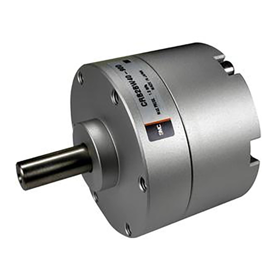
ROTARY ACTUATOR
Thoroughly read and understand this operation manual to install
and operate this product.
Pay particular attention to the safety statements.
Retain this operation manual to read whenever needed.
Model name
Part number / Series
Va n e Ty p e
C R B 2 B W 4 0
Doc.No.CRB2-OM00001-B
Advertisement
Table of Contents

Related Manuals for SMC Networks CRB2BW40 Series


Summary of Contents for SMC Networks CRB2BW40 Series
- Page 1 Doc.No.CRB2-OM00001-B Model name ROTARY ACTUATOR Part number / Series Va n e Ty p e C R B 2 B W 4 0 Thoroughly read and understand this operation manual to install and operate this product. Pay particular attention to the safety statements. ...
- Page 2 INDEX Precautions for Safety Front matter Product Description ・・・1 1-1. Model ・・・1 1-2. Specifications ・・・1 1-3. Effective Torque ・・・2 1-4. Key (Keyway) Position and Rotation Range ・・・2 Internal Construction and Description of Individual Parts ・・・3 2-1. Single Vane Type ・・・3 2-2....
-
Page 3: Safety Instructions
Safety Instructions These safety instructions are intended to prevent hazardous situations and/ or equipment damage. These instructions indicate the level of potential hazard with the labels of “Caution,” “Warning” or “Danger”. They are all important notes for safety and must be followed in addition to International Standards (ISO/ IEC) *1) Japan Industrial Standards (JIS) and other safety regulations. - Page 4 Warning 1. The compatibility of the product is the responsibility of the person who designs the equipment or decides its specifications. Since the product specified here is used under various operating conditions, its compatibility with specific equipment must be decided by the person who designs the equipment or decides its specifications based on necessary analysis and test results.
-
Page 5: Limited Warranty And Disclaimer / Compliance Requirements
Limited warranty and Disclaimer / Compliance Requirements The product used is subject to the following “Limited warranty and Disclaimer” and “Compliance Requirements”. Read and accept them before using the product. Limited warranty and Disclaimer 1. The warranty period of the product is 1 year in service or 1.5 years after the product is delivered, whichever is first. -
Page 6: Design / Selection
Design / Selection Warning (1) Confirm the specifications. Products represented in this catalog are designed only for use in compressed air systems. Do not operate at pressures or temperatures, etc., beyond the range of specifications, as this can cause damage or malfunction. (Refer to the specifications.) Please contact SMC when using a fluid other than compressed air. - Page 7 (12) Select a speed within the product’s allowable energy value. If the kinetic energy of the load exceeds the allowable value, it could damage the product, and cause a hazard to humans and damage the machinery and equipment. (13) Provide a shock absorber if the kinetic energy that is applied to the product exceeds the allowable value.
- Page 8 Mounting Warning (1) Operation manual Install the product and operate it only after reading the operation manual carefully and understanding its contents. Also, keep the manual in a location where it can be referred to as necessary. (2) Ensure sufficient space for maintenance activities. When installing the products, allow access for maintenance.
- Page 9 Precautions when Converting Rotational Motion to Linear Motion When using a link mechanism, etc., to convert rotational motion to linear motion, and determining the operation end using the stopper on the linear motion end (see below), a small value for θ at the operation end may result in the torque of the rotary actuator causing excessive radial load to act on the output axle, and equipment breakage may occur.
- Page 10 Piping Caution (1) Refer to the Fittings and Tubing Precautions (Best Pneumatics No.6) for handling one touch fittings. (2) Preparation before piping Before piping is connected, it should be thoroughly blown out with air (flushing) or washed to remove chips, cutting oil and other debris from inside the pipe.
-
Page 11: Air Supply
Air Supply Warning (1) Type of fluids Please consult with SMC when using the product in applications other than compressed air. (2) When there is a large amount of moisture Compressed air containing a large amount of moisture can cause malfunction of pneumatic equipment. An air dryer or water separator should be installed upstream from filters. -
Page 12: Maintenance
Maintenance Warning (1) Perform maintenance inspection according to the procedures indicated in the operation manual. If handled improperly, malfunction and damage of machinery or equipment may occur. (2) Maintenance work If handled improperly, compressed air can be dangerous. Assembly, handling, repair and element replacement of pneumatic systems should be performed by a knowledgeable and experienced person. - Page 13 Auto Switches Precautions Design / Selection Warning (1) Confirm the specifications. Read the specifications carefully and use this product appropriately. The product may be damaged or malfunction if it is used outside the range of specifications of current load, voltage, temperature or impact. We do not guarantee against any damage if the product is used outside of the specification range.
- Page 14 (3) Do not use a load that generates surge voltage. If a surge voltage is generated, discharge may be generated at the contact, possibly reducing the product life. If driving a load such as a relay that generates a surge voltage. <Reed>...
-
Page 15: Mounting / Adjustment
Mounting / Adjustment Caution (1) Do not drop or bump. Do not drop, bump or apply excessive impacts (300m/s or more for reed auto switches and 1000m/s or more for solid state auto switches) while handling. Although the body of the auto switch may not be damaged, the inside of the auto switch could be damaged and cause malfunction. -
Page 16: Operation Environment
(6) Avoid incorrect wiring. <Reed> A 24 VDC auto switch with indicator light has polarity. The brown lead wire or terminal No.1 is (+), and the blue lead wire or terminal No.2 is (-). 1) If connections are reversed, the auto switch will operate, however, the LED will not light up. Also, take note that a current greater than that specified will damage the LED and it will no longer operate. - Page 17 (3) Do not use in an environment with oil or chemicals. Please consult with SMC if auto switches will be used in an environment with coolant, cleaning solvent, various oils or chemicals. If auto switches are used under these conditions for even a short time, they may be adversely affected by improper insulation, malfunction due to swelling of the potting resin, or hardening of the lead wires.
-
Page 18: Product Description
1. Product Description This operation manual describes Vane Type of Rotary Actuator. Confirm the specifications of this product including load (moment of inertia), rotation time and other Operating conditions before the use. 1-1.Model Model Internal Volume(cm ) Weight(g) Port Size CRB2BW40-... - Page 19 1-3.Effective Torque 1-4.Key (Keyway) Position and Rotation Range Rotation Range/ View from Long Shaft (Parallel key position in each figure below is when Port B is pressurized).
- Page 20 2. Internal Construction and Description of Individual Parts 2-1.Single Vane Type Part Material Note Body (A) Aluminum Alloy White Body (B) Aluminum Alloy White Vane Shaft Carbon Steel (NBR) Stopper Resin For 270° Stopper Resin For 180° Bearing Bearing Steel Back-up Ring Stainless Steel Hexagon Socket Head Cap Screw...
- Page 21 2-2.Double Vane Type Part Material Note Body (A) Aluminum Alloy White Body (B) Aluminum Alloy White Vane Shaft Carbon Steel (NBR) Stopper Aluminum Die Casting For 90° Stopper Resin For 90° For 100° Stopper Aluminum Die Casting Bearing Bearing Steel Back-up Ring Stainless Steel Hexagon Socket Head Cap Screw...
-
Page 22: Basic Circuit
3. Basic Circuit 3-1.Circuit Configuration Figure 1 shows a basic circuit to activate Rotary Actuator by using Air Filter, Regulator, Solenoid Valve and Speed Controllers. Figure 1 3-2.Preferred Components Table 1 shows preferred components of solenoid valve, speed controller and tubing used In the basic circuit as Figure 1. -
Page 23: Installation
4. Installation 4-1.Air Supply Caution ① Filter and regulate air supplied to Rotary Actuator by using SMC Air Filter and Regulator (Series AR). ② Do not apply lubricant since this is non-lube type. Internal grease will be flowed out by lubrication so that normal operation will not be obtained. ③... - Page 24 ② It is recommended to use the method in Figure 2 to avoid applying direct load to the shaft for better operating conditions. Figure 2 4-4.Piping Caution Warning As Figure 3 shows, when actuator is used with extended shaft, center the shaft of Rotary Actuator and the counterpart.
- Page 25 4-5.Operating Environment Caution ① Do not use the product in atmospheres or places where there is a danger of corrosion. Refer to “internal” Construction and Description lf Individual Parts” (pages 3 and 4) for materials used for Rotary Actuator. ② Do not use the product in dusty places or where water and oil drops splash on. ③...
-
Page 26: Moment Of Inertia
5. How To Set Rotation Time Due to inertia of the load, even a small torque generated by Rotary Actuator may cause damage to the shaft and internal parts. Therefore, consider the inertia of the load and kinetic energy to set rotarion time. - Page 27 ③ How To Calculate Moment of Inertia Calculation of Moment of Inertia...
- Page 28 Graph 1 How To Read Graph 1. Example 1) When CRB2BW40 is used in conditions of moment of inertia of load kg・m inertia of load: 9.5x10 and rotation time: 0.12 sec/90°. kg.m Since the intersection of 9.5x10 on the vertical axis and 0.12 seconds on the horizontal axis is below the energy curve, CRB2BW40 is applicable.
- Page 29 5-2.Kinetic Energy Allowable kinetic energy of CRB2BW40 is 0.04 (J) when rubber cushion is used, and it is 0.03 (J) when rubber cushion is not used. Since Rotary Actuator reaches the rotation end during acceleration, terminal acceleration "ω" can be :...
- Page 30 5-3.External Stopper When kinetic energy generated by load exceeds allowable energy of Actuator, use external buffer mechanism to absorb inertia force. The figure below shows correct installation of external stopper. ※Rotary Actuator itself has a slight angular error due to the construction, use external stopper when accurate positioning is required.
-
Page 32: Maintenance And Check
6. Maintenance and Check ● Be sure to install Air Filter to clean supply air. ● Do not disassemble the actuator. When disassembling it for unavoidable reason, follow the procedures below while preventing dust and/or foreign matter from entering. [Since increase in internal leakage causes malfunction in most cases, recheck speed controller. It is recommended to use stable speed adjusting range (refer to “Speed Adjusting Range”... - Page 33 [Notes] ① Since any product disassembled will not be guaranteed, fully understand the internal construction before disassembling. ② Exercise caution not to damage packing when reassembling. ③ Use caution to prevent damage to sliding surfaces of Body (A) ①, Body (B) ② and Vane Shaft ⑥. ④...
-
Page 34: Troubleshooting
7. Troubleshooting Failure Possible causes Countermeasures Use the product within the specified speed Stable speed adjusting range is not satisfied. adjusting range. Increase in internal leakage due to internal Actuator does not Replace the vane shaft and stopper packing packing damage caused by foreign matter and/or operate. - Page 35 Revision history A:[Safety Instructions] Revision of sentences. : The contents have been revised to the latest version. 0120-837-838 4-14-1, Sotokanda, Chiyoda-ku, Tokyo 101-0021 JAPAN Tel: + 81 3 5207 8249 Fax: +81 3 5298 5362 http://www.smcworld.com Note: Specifications are subject to change without prior notice and any obligation on the part of the manufacturer. ©...
Need help?
Do you have a question about the CRB2BW40 Series and is the answer not in the manual?
Questions and answers