Table of Contents
Advertisement
Quick Links
Advertisement
Table of Contents

Related Manuals for SMC Networks CRA1 Series


Summary of Contents for SMC Networks CRA1 Series
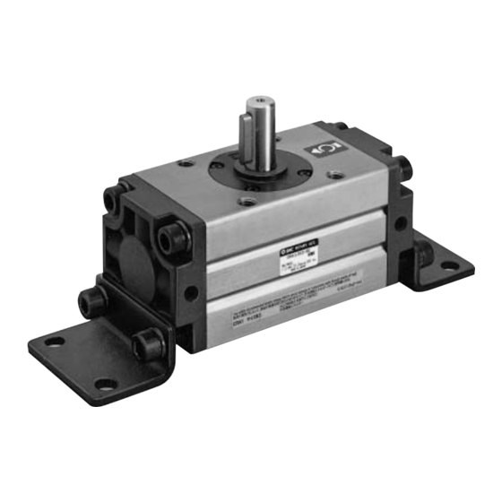
- Page 1 PRODUCT NAME Rotary Actuator MODEL / Series / Product Number CRA1 30~100 - 1 -...
-
Page 2: Table Of Contents
Contents Safety Instructions Outline Specification Effective torque Rotation range of Keyway Internal structure and parts description Rotary actuator internal structure Basic circuit for using rotary actuator Circuit configuration Recommended Devices Mounting Restriction of the load Operation of shaft couplings Piping and operating direction Operating air Setting rotation time Moment of inertia... -
Page 3: Safety Instructions
Rotary Actuator Safety Instructions These safety instructions are intended to prevent hazardous situations and/or equipment damage. These instructions indicate the level of potential hazard with the labels of “Caution,” “Warning” or “Danger.” They are all important notes for safety and must be followed in addition to International Standards (ISO/IEC) , and other safety regulations. - Page 4 Rotary Actuator Safety Instructions Caution 1.The product is provided for use in manufacturing industries. The product herein described is basically provided for peaceful use in manufacturing industries. If considering using the product in other industries, consult SMC beforehand and exchange specifications or a contract if necessary.
- Page 5 Design Warning ① If the operation involves load fluctuations, ascending/descending movements, or changes in friction resistance, make sure to provide safety measures. Failure to provide such measures could accelerate the movement, which may be hazardous to humans, machinery, and other equipment. ②...
- Page 6 ③ Provide a shock absorber if the kinetic energy that is applied to the product exceeds the allowable value. If the product’s kinetic energy exceeds the allowable value, it could damage the product, and cause a hazard to humans and damage the machinery and equipment. ④...
- Page 7 Backlash of the Single Rack Pinion Type CRA1 Series There is a backlash of within 1°at the rotation end of the CRA1 series. It is necessary to decide the position of the external stopper when precise rotation is required.
- Page 8 Air Supply Warning ① Use clean air. Do not use compressed air that contains chemicals, synthetic oils including organic solvents, salt or corrosive gases, etc., as it can cause damage or malfunction. Caution ① When extremely dry air is used as the fluid, degradation of the lubrication properties inside the equipment may occur, resulting in reduced reliability(or reduced service life) of the equipment.
- Page 9 Lubrication Warning ① This product should be used without lubrication. Although it will operate even if it is lubricated, it could lead to sticking or slipping. Maintenance and Inspection Warning ① During a maintenance inspection, do not disassemble the equipment with electrical power or an air supply applied.
- Page 10 ② Pay attention to the length of time that a switch is ON at an intermediate stroke position. When an auto switch is placed at an intermediate position of the stroke and a load is driven at the time the piston passes, the auto switch will operate, but if the speed is too great the operating time will be shortened and the load may not operate properly.
- Page 11 ⑤ Pay attention to leakage current. <Solid state switch / 2-wire type > Current (leakage current) flows to the load to operate the internal circuit even when in the OFF state. Operating current of load (OFF condition) > Leakage current If the criteria given in the above formula are not met, it will not reset correctly (stays ON).Use a 3-wire switch if this specification will not be satisfied.
- Page 12 ③ Observe the proper tightening torque for mounting an auto switch. When an auto switch is tightened beyond the range of tightening torque, auto switch mounting screws, auto switch mounting brackets or auto switch may be damaged. On the other hand, tightening below the range of tightening torque may allow the auto switch to slip out of position.
- Page 13 ⑥ Avoid incorrect wiring. <Reed switch> A 24 VDC auto switch with indicator light has polarity. The brown lead wire or terminal No.1 is (+), and the blue lead wire or terminal No.2 is (-). 1) If connections are reversed, an auto switch will operate, however, the light emitting diode will not light Also, take note that a current greater than that specified will damage a light emitting diode and it will no longer operate.
- Page 14 ⑦ Do not use in an area where surges are generated. <Solid state switch> When there are units (solenoid lifter, high frequency induction furnace, motor, radio equipment etc.) which generate a large amount of surge in the area around cylinders/actuators with solid state auto switches, this may cause deterioration or damage to the auto switch’s internal circuit elements.
- Page 15 Rotary Actuator How to Use the Air-hydro Type ・Caution on Design Warning ① Do not use a rotary actuator of the air-hydro type near flames, or in equipment or machinery that exceeds an ambient temperatures of 60℃. There is a danger of causing a fire because the rotary actuator of the air-hydro type uses a flammable hydraulic fluid.
- Page 16 ・Piping Caution ① Use self-align fitting in conjunction with the piping for the rotary actuator of the air-hydro type. Do not use a one-touch fitting with the piping for the rotary actuator of the air-hydro type, as this may result in oil leakage. ②...
-
Page 17: Outline
Outline This operation manual is for rack pinion type Rotary actuator. Cautions will be given on the load (inertia moment), rotation time and others. Please read through the manual before starting operation. Specification Table (1) Specification Type Pneumatic Air-hydro Size Fluid Air(Non-lube) Hydraulic oil... -
Page 18: Effective Torque
Table (4) Rotary actuator inner volume Rotation angle Size 90° 100° 180° 190° ― ― Effective torque Table (5) Effective torque table (N・m) Operating pressure (MPa) Size 0.38 0.76 1.14 1.53 1.91 2.29 2.67 3.05 3.44 3.82 1.85 3.71 5.57 7.43 9.27 11.2... -
Page 19: Rotation Range Of Keyway
Rotation range of keyway If air pressure is applied from the A port side, the shaft rotates clockwise. If air pressure is applied from the B port side, the shaft rotates counterclockwise. Size 30 Stopper screw A:For end adjustment in clockwise direction Stopper screw B:For end adjustment in counter clockwise direction Fig. -
Page 20: Internal Structure And Parts Description
Internal structure and parts description Rotary actuator internal structure Component parts Description Number Note Body Anodized Cover Black Piston Ass’y Shaft Bearing retainer Black Description Number Note Nameplate Rack Anodized Rotation display plate Slider Black Tube gasket Zinc Chromated Spring pin Slider O-ring Connecting Bearing... -
Page 21: Basic Circuit For Using Rotary Actuator
Basic circuit for using rotary actuator Circuit configuration The basic circuit for operating the rotary actuator using an air filter, regulator, solenoid valve, and speed controller is shown in Fig. (6). Speed controller Regulator Air filter Solenoid Rotary actuator valve Fig. -
Page 22: Mounting
Mounting Restriction of the load Provided that a dynamic load is not generated, a load in the axial direction can be applied up to the value that is indicated in the table (8) below. However, applications in which the load is applied directly to the shaft should be avoided as much as possible. -
Page 23: Piping And Operating Direction
Also, if pipe tape is used, as in Fig. (11), leave 1.5 to 2 thread ridges exposed at the end of the threads. Operating air Air supplied to the rotary actuator shall be cleaned by the filter. CRA1 series is lubrication free. Fig. (9) Wrapping of pipe tape - 23 -... -
Page 24: Setting Rotation Time
Setting rotation time Even if the torque that is generated by the rotary actuator is small, the parts could become damaged depending on the inertia of the load. Therefore, the rotation time should be determined by calculating the load’s inertial moment and kinetic energy. Moment of inertia Inertia moment indicates scales how hard to rotate the object, and also how hard to stop rotating object. - Page 25 Equation table of moment of inertia I:Moment of inertia kg・m m:Load mass kg ① Thin shaft ⑥ Thin round plate Position of rotational axis: Perpendicular to the Position of rotational axis: Through the center of shaft through the center of gravity. diameter ②...
-
Page 26: Kinetic Energy
Kinetic energy Table (9) shows the allowable kinetic energy of the rotary actuator. The end angular speed ωis obtained by: Table (9) Allowable kinetic energy Allowable kinetic energy (J) Size With Without θ:Rotation angle ※ Air Cushion Air Cushion (90°:1/2πrad) ―... -
Page 27: External Stopper
There is backlash of the gear because the CRA1 series is a single rack type. (It is within 1° at the rotation end.) When there is no backlash, and an accurate positional precision is necessary, an external stopper is needed. -
Page 28: Calculation Of Required Torque
Calculation of required torque Load type The calculation method of required torque varies depending on the load type. - 28 -... -
Page 29: Maintenance And Inspection
Maintenance and Inspection Periodic inspection is necessary for optimum use. Generally, annual inspection is recommended for the rotary actuator. Even if no problem is found, seal parts replacement is recommended every three years. It is highly possible that the actuator is operated out of specification when the components like shaft, pinion, rack, bearing are broken. -
Page 30: Disassembly Drawing
Disassembly drawing Table (10) Parts where grease is to be applied Application of grease Grease Body (inner sliding surface) Piston (Seal groove) Slider (Sliding surface) GR-S-10 Tube gasket Piston seal Pinion gear BR2-Plus Rack - 30 -... -
Page 31: Troubleshooting
Troubleshooting Refere Problem Possible cause Solution page Supply pressure isn’t Correctly set the regulator at the supply applied correctly. pressure side. The directional switching Correctly apply a signal to the valve (such as a directional switching valve (such as a solenoid valve) doesn’t solenoid valve). - Page 32 Refere Problem Possible cause Solution page Please confirm the presence of the wound in the cylinder inner wall after cleaning the inside of the cylinder. Please do the following treatment on that. (1)Please exchange packing when there is no wound in the cylinder. Air leakage from Piston packing is worn the shaft.
- Page 33 Refere Problem Possible cause Solution page External stopper remove, and please confirm the range of all swings of the actuator, and install external stopper in There is no margin on correct position. swing angle of actuator, In this case, please provide a buffer hence swing range of angle to the stroke of the actuator actuator is...
- Page 34 Revision history A: Change from non-SI unit to SI unit B: Fix unclear areas C: Fix unclear areas D: Grease name changed E: Format change , Additional tightening torque 4-14-1, Sotokanda, Chiyoda-ku, Tokyo 101-0021 JAPAN Tel: + 81 3 5207 8249 Fax: +81 3 5298 5362 https://www.smcworld.com Note: Specifications are subject to change without prior notice and any obligation on the part of the manufacturer.
Need help?
Do you have a question about the CRA1 Series and is the answer not in the manual?
Questions and answers