Table of Contents
Advertisement
Quick Links
Advertisement
Table of Contents

Related Manuals for DALBO MAXIDISC 300


Summary of Contents for DALBO MAXIDISC 300
- Page 1 MAXIDISC 300, 400 cm...
- Page 3 Congratulations on the purchase of your new MAXIDISC. To ensure safe operation and to ob- tain optimal use of the machine, read the rules and instructions of the following operator’s manual carefully before operating the machine. © Copyright 2002, DALBO. All rights reserved. Your MAXIDISC: Type No.: Serial No.:...
-
Page 5: Table Of Contents
MAXIDISC Table of Contents TABLE OF CONTENTS ........................5 SAFETY ............................7 ............................7 ENERAL ..........................8 YDRAULIC YSTEM ............................8 ITCHING ........................8 AINTENANCE AND EPAIRS ............................9 RANSPORT ............................. 9 ORRECT TECHNICAL DATA ......................... 10 HOW TO USE THIS MANUAL ......................11 ............................ - Page 6 SPARE PARTS ..........................27...
-
Page 7: Safety
MAXIDISC Safety The safety alert symbol is used throughout this manual to identify important safe- ty warning messages concerning your safety, the safety of other users or the func- tional safety of the implement. Observe all safety instructions and make them readily accessible to all users of the equipment. -
Page 8: Hydraulic System
MAXIDISC Hydraulic System • Never allow bystanders within the operating radius of the MAXIDISC when the hydraulic system is activated to avoid the danger of an individual being crushed or pinched between the equipment. • Before performing maintenance or repairs on the hydraulic system, lower the implement to the ground, relieve pressure in the system, turn off the engine and remove the ignition key. -
Page 9: Transport
MAXIDISC • Dispose of oil, grease and filters according to applicable environmental regula- tions. Transport • All safety and warning signs and devices required by law must be displayed, mounted and tested for public road use. The driver is responsible for the cor- rect use of lights and markings in compliance with the present Traffic Act and Highway Code of the local traffic legislation. -
Page 10: Technical Data
MAXIDISC Technical Data MAXIDISC Size (cm) HP (recommended) Gross weight kg: 1720 2290 T-rings Side 10... -
Page 11: How To Use This Manual
MAXIDISC How to Use This Manual If the order of points described under the main subject areas of the manual seems confusing or illogical, refer to the Table of Contents where all subject headings can be found. The main points of the operator’s manual are placed into five main categories: •... -
Page 12: Application
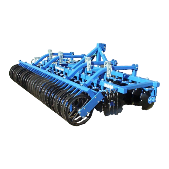
MAXIDISC Application MAXIDISC represents a whole new generation of lift-mounted disc harrows provid- ing the ultimate in compactness. The MAXIDISC is specially designed for work in the uppermost soil layer where resi- due management is concentrated. The MAXIDISC effectively performs full cutting penetration of the field and uniform mixing and blending of plant residue and soil microorganisms in just one pass. -
Page 13: Hitching And Unhitching
MAXIDISC Hitching and Unhitching Hitching Fig. 2 Attach the lift arms first and then the top link. Adjust the top link so that the frame is horizontal. • Remember to secure with lynch pins. Hydraulic System The MAXIDISC requires one double-acting hydraulic outlet. Table 1. -
Page 14: Adjustments And Settings
MAXIDISC Adjustments and Settings The MAXIDISC is preset in the factory, but it will always be necessary to make some fine adjustments before use. Numerous adjustment possibilities make your MAXI- DISC more versatile and allow you to obtain optimum performance from the imple- ment. -
Page 15: Angle
MAXIDISC 300 (80150) 23/20 ; 3/0 MAXIDISC 400 (80160) 20/20 ; 0/0 MAXIDISC 400 (80160) 23/20 ; 3/0 MAXIDISC 300 Ü (80151) 20/20 ; 0/0 MAXIDISC 300 Ü (80151) 23/20 ; 3/0 MAXIDISC 400 Ü (80161) 20/20 ; 0/0 MAXIDISC 400 Ü (80161) 23/20 ;... -
Page 16: Disc Scrapers
MAXIDISC Disc scrapers Fig. 5 Adjust the disc scrapers, allowing only 3 to 5 mm of space between each disc and scraper. Side discs Fig. 6 A disc mounted on the outside edge of the MAXIDISC limits the amount of soil being cast out by the disc in the very front. -
Page 17: Operating And Driving Instructions
MAXIDISC Operating and Driving Instructions Proper operation is essential for optimum performance of your MAXIDISC. Proper operation concerns both the carrying out of tillage operations in the field as well as the following of safety precautions. Make sure that you have a thorough under- standing of all safety precautions. -
Page 18: Troubleshooting
MAXIDISC Troubleshooting Problem Cause Action • MAXIDISC is not • Adjust the top link until the main Soil is thrown too far out to the sides, horizontal. frame is horizontal. creating a ridge. • The travel speed • Drive slower. is too fast. -
Page 19: Maintenance
MAXIDISC Maintenance Proper maintenance ensures a long life for the MAXIDISC and also optimum perfor- mance from the implement. To facilitate maintenance, grease fittings have been mounted on those locations where wear on the equipment is the greatest. Tighten all nuts, bolts, hydraulic fittings or any other fastened as- semblies after the first workday. -
Page 20: Hydraulic System
MAXIDISC Hydraulic System Inspect all hydraulic hoses for chafing or leaks. Check hoses for pinching. To avoid rust, any projecting piston rods should be coated with oil or grease if the MAXIDISC is to be parked for a long period of time. Remember to remove the oil or grease prior to operation. -
Page 21: Replacements And Repairs
MAXIDISC Replacements and Repairs Safety is important in connection with all repair work on the MAXI- DISC. The following safety precautions and the precautions listed in the beginning of this manual must be observed. Before performing any adjustments, maintenance or repairs on the machinery, always unfold the MAXIDISC and lower the im- plement to the ground or secure in transport position, set the tractor brakes, turn off the engine and remove the ignition key... -
Page 22: Replacing Angle Adjustment Seals
MAXIDISC Replacing angle adjustment seals Fig. 10 Cylinder 50/30-150 1 Empty the oil from the cylinder by carefully moving the cylinder back and forth. 2 Move the piston to the middle position. Unscrew the gland (pos. 3) from the cylinder casing (pos. 1). (A special tool is needed to remove the gland). If the gland is stuck, it may help to warm up the very front of the socket. -
Page 23: Replacing Shaft, Bearings And T-Rings
MAXIDISC Replacing shaft, bearings and T-rings Lower the MAXIDISC to the ground. Securely support and block the roller if neces- sary. Watch out for unintentional rolling movement when the bolts in the bearings have been removed. Fig. 11 1 Remove the bolts in the bear- ings. - Page 24 MAXIDISC Fig. 13 1 Remove the disc. 2 Unscrew the cap (21). 3 Take out the split cotter pin (20) holding the castle nut. 4 Remove the castle nut (19). 5 Pull off the hub (22) with a wheel puller. 6 Slide off the inner bearing.
-
Page 25: Scrapping
MAXIDISC Scrapping Relieve the pressure in the hydraulic system. When dismounting/mounting components, always pay atten- tion to the weight of the part that you are about to handle. It is important to support or secure the part so that it cannot fall. Dismount all hydraulic hoses and cylinders and empty the oil. -
Page 26: Hydraulic System Diagram
MAXIDISC Hydraulic System Diagram Hydraulic diagram for angle adjustment Fig. 14 Side 26... - Page 27 MAXIDISC Spare Parts Side 27...
Need help?
Do you have a question about the MAXIDISC 300 and is the answer not in the manual?
Questions and answers