Table of Contents
Advertisement
Quick Links
Advertisement
Table of Contents

Related Manuals for Major tech MT1877IV


Summary of Contents for Major tech MT1877IV
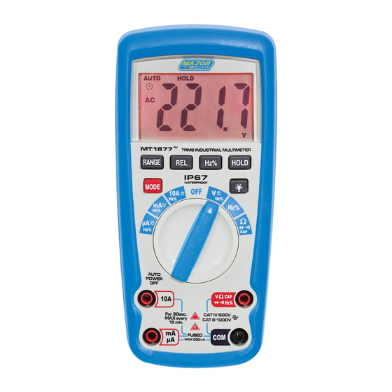
- Page 1 INSTRUCTION MANUAL MT1877 1000V AC/DC TRMS MULTIMETER...
-
Page 3: Table Of Contents
Contents Page no 1. Safety Warnings ................4 2. Safety Symbols .................4 3. Operation ................5 3.1. Mode Button ................5 3.2. Backlight Button ..............5 3.3. Data Hold Button..............6 3.4. Range Button................6 3.5. REL Button................6 3.6. Hz/Duty Button................6 3.7. AC/DC Voltage Measurement............6 3.8. DC Current Measurement............7 3.9. -
Page 4: Safety Warnings
1. SAFETY WARNINGS The following safety information must be observed to insure maximum personal safety during the operation of this meter: • Measurements beyond the maximum selected range must not be attempted. • Extreme care must be taken when measuring above 50 V, especially on live bus-bars. -
Page 5: Operation
This symbol advises the user that the terminal(s) so marked must not be connected to a circuit point at which the 1000V voltage with respect to earth ground exceeds (in this case) 1000 VAC or VDC. Equipment protected throughout by Double Insulation (Class 11) Equipment complies with current EU directives. -
Page 6: Data Hold Button
3.3. DATA HOLD BUTTON The Data Hold function allows the meter to "freeze" a measurement for later reference. 1. Press the Data Hold button to "freeze" the reading on the indicator. The indicator "HOLD" will be appear in the display. 2. -
Page 7: Dc Current Measurement
3.8. DC CURRENT MEASUREMENT 1. Insert the black test lead banana plug into the negative (COM) jack. 2. For current measurements up to 4000uA DC, set the function switch to the uA position and insert the red test lead banana plug into the (uA) jack. -
Page 8: Continuity Check
1. Set the function switch to the position. 2. Insert the black test lead plug into the negative (COM) socket and the red test lead plug into the positive n jack. 3. Press the MODE button until "Ω" appears on the display. 4. -
Page 9: Capacitance Measurement
3.13. CAPACITANCE MEASUREMENT WARNING: To avoid electric shock, discharge the capacitor under test before measuring. 1. Set the function switch to the CAP capacitance position. Press the MODE button until "nF" appears on the display. 2. Insert the black test lead banana plug into the negative COM jack and the red test lead banana plug into the CAP positive jack. -
Page 10: Specifications
4. SPECIFICATIONS Range Function Insulation Class2, Double insulation. Over voltage category CAT IV 600V, CAT III 1000V Maximum voltage between any terminal 1000V DC/AC RMS and earth ground Surge Protection Peak IEC 61010 Display 4000 counts LCD display, 21mm high Polarity Automatic, (-) negative polarity indication. -
Page 11: Non-Contact Voltage (Ncv)
4.1. NON-CONTACT VOLTAGE (NCV) The NCV function works on any rotary switch position. 1. Test the detector on a known live circuit before use. 2. Hold the top of the meter very close to the voltage source as shown. 3. If voltage is present, the back light will flash a bright red. Range Function Low battery indication... -
Page 12: Dc Voltage (Auto-Ranging)
4.2. DC VOLTAGE (AUTO-RANGING) Range Resolution Accuracy 400.0mV 0.1mV 4.000V ± 0.5% of rdg ± 5 digits 40.00V 10mV 400.0V 100mV ± 0.6% of rdg ± 6 digits 1000V Input Impedance: 10MΩ. Maximum Input: 1000V DC or 1000V AC RMS. 4.3. -
Page 13: Ac Current (Auto-Ranging)
4.5. AC CURRENT (AUTO-RANGING) Range Resolution Accuracy 400.0uA 0.1uA 4000uA ±1.5% of rdg ± 3 digits 40.00mA 10uA 400.0mA 100uA 4.000A ±2.0% of rdg ± 3digits 10mA Overload protection: 500mA / 1000V and 10A / 1000V Fuse. All AC Current ranges are specified from 5% of range to 100% of range. AC Current 50Hz to 1 kHz (Sine);... -
Page 14: Frequency (Electronic)
4.8. FREQUENCY (ELECTRONIC) Range Resolution Accuracy 9.999Hz 0.001Hz 99.99Hz 0.01Hz 999.9 Hz 0.1Hz 9.999KHz 1 Hz ±1.0% of rdg ± 5 dgts 99.99kHz 10Hz 999.9kHz 100Hz 9.999MHz 1kHz 10.00MHz 10KHz Sensitivity: >0.5V RMS while ≤1 MHz ; Sensitivity: >3V RMS while >1 MHz; Input Protection: 250V DC or 250V AC RMS. -
Page 15: Battery And Fuse Replacement
5. BATTERY AND FUSE REPLACEMENT WARNING: To avoid electric shock, disconnect the test leads from any source of voltage before removing the battery cover. 1. When the batteries become flat or drop below the operating voltage, the battery warning symbol will appear on the LCD display. The battery should be replaced. - Page 16 MAJOR TECH (PTY) LTD South Africa Australia www.major-tech.com www.majortech.com.au sales@major-tech.com info@majortech.com.au...
Need help?
Do you have a question about the MT1877IV and is the answer not in the manual?
Questions and answers