
Related Manuals for H3C SecPathT5030


Summary of Contents for H3C SecPathT5030
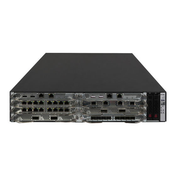
- Page 1 H3C SecPathT5030/T5060/T5080/T5000-S/ T5000-C Intrusion Prevention System Installation Guide New H3C Technologies Co., Ltd. http://www.h3c.com Document version: 6W101-20220620...
- Page 2 The information in this document is subject to change without notice. All contents in this document, including statements, information, and recommendations, are believed to be accurate, but they are presented without warranty of any kind, express or implied. H3C shall not be liable for technical or editorial errors or omissions contained herein.
- Page 3 Preface The installation guide provides information on preparing for installation, installing, accessing, replacing, maintaining, and troubleshooting H3C SecPath T5000 IPS series. This preface includes the following topics about the documentation: • Audience. • Conventions. • Documentation feedback. Audience This documentation is intended for: •...
- Page 4 Symbols Convention Description An alert that calls attention to important information that if not understood or followed WARNING! can result in personal injury. An alert that calls attention to important information that if not understood or followed CAUTION: can result in data loss, data corruption, or damage to hardware or software. An alert that calls attention to essential information.
- Page 5 Documentation feedback You can e-mail your comments about product documentation to info@h3c.com. We appreciate your comments.
-
Page 6: Table Of Contents
Contents Preparing for installation ················································································ 1 Safety recommendations ··································································································································· 1 Safety symbols ··········································································································································· 1 General safety recommendations ·············································································································· 1 Electrical safety ·········································································································································· 2 Laser safety ················································································································································ 2 Moving safety ············································································································································· 2 Examining the installation site ···························································································································· 3 Weight support ··········································································································································· 3 Temperature and humidity ·························································································································... - Page 7 Displaying electrical label information for the device ······················································································· 30 Displaying the CPU usage of the device ·········································································································· 30 Displaying the memory usage of the device ···································································································· 31 Displaying the operational status of power supplies ························································································ 32 Displaying temperature information for the device ··························································································· 32 Displaying the operational status of fan trays ··································································································...
-
Page 8: Preparing For Installation
Preparing for installation Safety recommendations To avoid any equipment damage or bodily injury, read the following safety recommendations before installation. Note that the recommendations do not cover every possible hazardous condition. Safety symbols When reading this document, note the following symbols: WARNING means an alert that calls attention to important information that if not understood or followed can result in personal injury. -
Page 9: Electrical Safety
• Make sure the operating voltage for the power supply is in the required range. • Use a screwdriver to fasten screws. • Take away the packaging materials and installation tools after installation. Electrical safety • Carefully examine your work area for possible hazards such as moist floors, ungrounded power extension cables, and missing safety grounds. -
Page 10: Examining The Installation Site
Examining the installation site The device can only be used indoors. To ensure correct operation and a long lifespan for your device, the installation site must meet the following requirements. Weight support Make sure the floor can support the total weight of the rack, chassis, modules, and all other components. -
Page 11: Cooling System
Table 4 Harmful gas limits in an equipment room Max. (mg/m 0.006 0.05 0.01 0.04 Cooling system IMPORTANT: For good heat dissipation, make sure the following requirements are met: • The installation site has a good cooling system. • There is a minimum clearance of 100 mm (3.94 in) around the inlet and outlet air vents of the chassis. -
Page 12: Esd Prevention
ESD prevention To prevent electrostatic discharge (ESD), follow these guidelines: • Make sure the device and the rack are reliably grounded. • Take dust-proof measures for the equipment room. For more information, see "Cleanliness." • Maintain the humidity and temperature at acceptable levels. For more information, see "Temperature and humidity."... -
Page 13: Power Supply
IMPORTANT: No network port lightning arrester or AC power lightning arrester is provided with the device. Prepare them as required. For the technical specifications and installation instructions for the lightning protectors, see the documents shipped with them. Power supply Verify that the power system at the installation site meets the requirements of the power supplies, including the input method and rated input voltage. - Page 14 Item Requirements • site A good cooling system is available at the installation site. • Operating: Without drives: 0°C to 45°C (32°F to 113°F) Temperature With drives: 5°C to 40°C (41°F to 104°F) • Storage: –40°C to +70°C (–40°F to +158°F) •...
-
Page 15: Installing The Device
Keep the tamper-proof seal on a mounting screw on the chassis cover intact, and if you want to open the chassis, contact the local agent of H3C for permission. Otherwise, H3C shall not be liable for any consequence caused thereby. -
Page 16: Installing The Device In A Standard 19-Inch Rack
The grounding screw at the primary grounding point is also applicable to the auxiliary grounding point. If you are to use the auxiliary grounding point for grounding the device, attach the grounding cable to the auxiliary grounding point before mounting the device in the rack. The grounding cable connection procedure is the same for the primary grounding point and the auxiliary grounding point. - Page 17 handle at the chassis rear To install the device in a 19-inch rack: Wear an ESD wrist strap and unpack the device and accessories. Make sure the rack is sturdy and reliably grounded. Use a mounting bracket to mark the cage nut installation positions on the rack posts. Four cage nuts are required on each front rack post and two are required on each rear rack post.
-
Page 18: Installing A Power Supply
Figure 5 Attaching the mounting brackets and chassis rails to the device Supporting the bottom of the device, align the chassis rails with the slide rails and slide the slide rails into the chassis rails until the mounting brackets are flush against the front rack posts. Use M6 rack screws to secure the mounting brackets to the front rack posts. - Page 19 To install a power supply: Remove the filler panel, if any, from the power supply slot. The device comes with power supply PWR1 installed with a filler panel and power supply PWR2 empty. Figure 7 Removing the filler panel Install the power supply. a.
-
Page 20: Installing A Fan Tray
Installing a fan tray CAUTION: • Before installing a fan tray, make sure the airflow direction provided by the fan tray meets the ventilation requirements. • The device comes with both fan tray slots empty. To ensure good ventilation, you must install two fan trays of the same model before powering on the device. -
Page 21: Installing An Interface Module
Installing an interface module CAUTION: • Do not hot swap interface modules. • To avoid module damage, do not touch the surface-mounted components on an interface module directly with your hands. • Install a filler panel over empty interface module slots to prevent dust and ensure good ventilation in the chassis. -
Page 22: Installing A Drive
• Do not hot swap drives. • The device does not come with any drives and cannot recognize drives from other vendors. Purchase drives from H3C as needed. • To avoid ESD damage, wear an ESD wrist strap when installing or removing a drive. -
Page 23: Connecting A Fiber Port
QSFP+ transceiver modules. For the transceiver module specifications, see port specifications in "Appendix A Chassis and FRU views and technical specifications." No transceiver modules are provided with the device. As a best practice, use H3C transceiver modules for the device. - Page 24 Figure 13 10GE SFP+ transceiver module Figure 14 40GE QSFP+ transceiver module To connect a fiber port: Remove the dust plug from the fiber port. Pull the bail latch on the transceiver module upwards to catch the knob on the top of the transceiver module.
-
Page 25: Connecting Power Cords
Connecting power cords CAUTION: Make sure the grounding cable of the device is correctly connected and the power source is powered off before connecting the power cord. Connecting an AC power cord Connect one end of the AC power cord to the AC-input power receptacle on the power supply. Use a removable cable tie to secure the AC power cord to the power supply handle. -
Page 26: Verifying The Installation
Figure 17 Connecting a DC power cord Verifying the installation Verify the following items to ensure correct installation: • There is enough space around the device for heat dissipation. • The device and its components are installed securely. The screws are fastened tightly. •... -
Page 27: Accessing The Device For The First Time
The fan blades are rotating and air is exhausted from the air outlet vents. • The configuration terminal displays the following: System is starting... Press Ctrl+D to access BASIC-BOOTWARE MENU... Press Ctrl+T to start heavy memory test.. Booting Normal Extended BootWare The Extended BootWare is self-decompressing..Done. **************************************************************************** H3C SecPath BootWare, Version 1.05... -
Page 28: Logging In To The Device
**************************************************************************** Copyright (c) 2004-2017 New H3C Technologies Co., Ltd. Compiled Date : Aug 31 2017 Memory Type : DDR3 SDRAM Memory Size : 16384MB Flash Size : 8MB sda0 Size : 3728MB CPLD Version : 1.0 PCB Version : Ver.B BootWare Validating... -
Page 29: Logging In From The Web Interface
• Username—admin • Password—admin To access the device from the console port: Use a console cable to connect the console port on the device to a configuration terminal, for example, a PC. Run a terminal emulator program, TeraTermPro or PuTTY, on your configuration terminal. For more information about the terminal emulator programs, see the user guides for these programs. - Page 30 Run the Telnet client on the PC and enter the login information.
-
Page 31: Hardware Replacement
Hardware replacement CAUTION: Wear an ESD wrist strap or ESD gloves for hardware maintenance. They are not provided with the device. Prepare them yourself. Replacing a fan tray WARNING! • To avoid bodily injury, do not touch an operating fan tray. •... -
Page 32: Replacing An Interface Module
To remove a DC power cord, squeeze the upper and lower sides of the plug and then pull the plug out. Figure 19 Removing a DC power cord Holding the handle on the power supply with one hand, press the retaining latch on the power supply to the right with your thumb, and pull the power supply part way out of the slot. -
Page 33: Replacing A Drive
Put the removed module on an antistatic workbench or into an antistatic bag with the circuit board facing upward. Install a new interface module. For the installation procedure, see "Installing an interface module." Figure 21 Removing an interface module (1) Loosen the captive screws (2) Pull the ejector levers outward (3) Pull the module out of the slot Replacing a drive... -
Page 34: Replacing A Transceiver Module
Figure 22 Removing a drive Replacing a transceiver module WARNING! Disconnected optical fibers or transceiver modules might emit invisible laser light. Do not stare into beams or view directly with optical instruments when the device is operating. CAUTION: • Do not touch the golden plating on a transceiver module during the replacement process. •... - Page 35 Figure 24 Removing a transceiver module Install dust caps for the removed transceiver module, and then put it into the package. Install a new transceiver module. For the installation procedure, see "Connecting a fiber port."...
-
Page 36: Hardware Management And Maintenance
<Sysname> display version H3C Comware Software, Version 7.1.064, Test XXXX Copyright (c) 2004-2017 New H3C Technologies Co., Ltd. All rights reserved. H3C SecPath T5000-S uptime is 0 weeks, 2 days, 21 hours, 1 minute Last reboot reason: User reboot Boot image: sda0:/MAIN-CMW710-BOOT-XXXX.bin Boot image version: 7.1.064, Test XXXX... -
Page 37: Displaying Electrical Label Information For The Device
<Sysname> display device manuinfo Slot 1 CPU 0: DEVICE_NAME : Secpath T5000-S DEVICE_SERIAL_NUMBER : 210235A3KXH17A000022 MAC_ADDRESS : 74EA-C8C5-8EEB MANUFACTURING_DATE : 2017-11-08 VENDOR_NAME : H3C … Table 10 Output description Field Description DEVICE_NAME Device name DEVICE_SERIAL_NUMBER Device serial number MAC_ADDRESS MAC address of the device... -
Page 38: Displaying The Memory Usage Of The Device
Table 11 Output description Field Description Slot 1 CPU 0 CPU usage CPU 0 usage information for the interface module in slot 1. Average CPU usage in the last 5 seconds. (After the device boots, the device 0% in last 5 seconds calculates and records the average CPU usage at intervals of 5 seconds.) Average CPU usage in the last minute. -
Page 39: Displaying The Operational Status Of Power Supplies
Displaying the operational status of power supplies Use the command to display the operational status of power supplies. display power <Sysname> display power Slot 1 Power Status: Normal Slot 1 Power Status: Absent Table 13 Output description Field Description Power Number of the power supply. -
Page 40: Displaying The Operational Status Of Fan Trays
Field Description High temperature shutdown threshold. The device automatically powers off Shutdown-UpperLimit when the temperature exceeds this threshold. Displaying the operational status of fan trays Use the command to display the operational status of fan trays. display fan <Sysname>display fan SLOT 1 Fan 0-0 Status: Normal Speed:7692... -
Page 41: Displaying Transceiver Module Information
To view the diag.gz file: a. Execute the command in user view to tar extract archive-file diag.tar.gz decompress the file. b. Execute the command. gunzip diag.gz c. Execute the diag command. more d. Press Page Up and Page Down. • Display the operational statistics for each functional module of the device: <Sysname>... - Page 42 To reboot the device immediately: Task Command Remarks reboot Reboot the device immediately. Available in user view. To schedule a reboot: Task Command Remarks Schedule a reboot to occur at a Use either command. scheduler reboot at specific time or date. By default, no reboot date or time or reboot delay time is specified.
-
Page 43: Troubleshooting
Verify that the power supply is as required by the device. Verify that the power cords of the device are firmly connected. Verify that the power cords are not damaged. If the issue persists, contact H3C Support. Configuration terminal display problem Symptom The configuration terminal displays nothing or garbled text when the device is powered on. -
Page 44: High Operating Temperature
%Nov 28 20:02:59:085 2019 H3C DEV/4/TEMPERATURE_WARNING: -Context=1; Temperature is greater than the high-temperature warning threshold on slot 1 sensor outflow 1. Current temperature is 58 degrees centigrade. -
Page 45: Appendix A Chassis Views And Technical Specifications
Appendix A Chassis views and technical specifications Chassis views Front panel On the front panel, the device provides eight interface module slots and two drive slots. Figure 25 Front panel (1) Interface module slots 1 through 8 (2) Drive slot HD0 (3) Drive slot HD1 (4) LEDs Rear panel... -
Page 46: Expansion Slots
(3) Console port (CONSOLE) (4) USB port (host mode, type A) (5) Fan tray slot FAN0 (6) Fan tray slot FAN1 (7) Power supply slot PWR0 (8) Grounding screw (9) Power supply slot PWR1 (10) Management Ethernet port (MGMT) Expansion slots Table 16 Expansion slots on the device Device model Interface module slots... -
Page 47: Nsqm1Qg2A
Figure 27 NSQM1TG8A front view (1) LED (2)10GBASE-R fiber ports (3) Captive screw (4) Ejector lever NSQM1QG2A The NSQM1QG2A interface module provides two 40GBASE-R fiber ports. Figure 28 NSQM1QG2A front view (1) LED (2) 40GBASE-R fiber ports (3) Captive screw (4) Ejector lever NSQM1G4XS4 The NSQM1G4XS4 interface module provides four 10GBASE-R fiber ports (10G-SR/LR) and four... -
Page 48: Nsqm1Gp8A
Figure 30 NSQM1GT8A front view (1) LED (2) 10/100/1000BASE-T copper ports (3) Captive screw (4) Ejector lever NSQM1GP8A The NSQM1GP8A interface module provides eight 1000BASE-X fiber ports. Figure 31 NSQM1GP8A front view (1) LED (2) 1000BASE-X fiber ports (3) Captive screw (4) Ejector lever NSQM1GT4PFCA The NSQM1GT4PFCA interface module provides four 10/100/1000BASE-T copper ports that... -
Page 49: Psr650B-12A1 Ac Power Supply
The device provides two power supply slots: PWR0 and PWR1. It comes with PWR1 installed with a filler panel and PWR0 empty. You can install one power supply, or two power supplies in 1+1 redundancy for the device. When two power supplies are installed, you can hot swap one. No power supplies are provided with the device. -
Page 50: Fan Trays
Fan trays CAUTION: For adequate heat dissipation, make sure two fan trays of the same model are installed on the device before powering on the device. The device provides two fan tray slots: FAN0 and FAN1 and supports the FAN-20F-2-A and FAN-20B-2-A fan trays. -
Page 51: Fan-20B-2-A
FAN-20B-2-A Figure 36 FAN-20B-2-A (1) Handle (2) Alarm LED Technical specifications Dimensions and weights The total weight of the device includes the chassis and the removable components. Table 18 Dimensions and weights Model Dimensions (H × W × D) Weight T5030/T5060/T5080/T5000-S/T 88.1 ×... -
Page 52: Storage
Storage Table 19 Storage specifications Device model Memory T5030/T5000-C 16 GB DDR3 T5060/T5000-S 32 GB DDR3 T5080 64 GB DDR3 Power consumption The total power consumption of the device includes the chassis and the removable components. Table 20 Power consumption Item Specification T5030/T5060/T5080/T5000-C chassis... -
Page 53: Fan Trays
Fan trays Table 23 Fan tray specifications Item Specification Dimensions (H × W × D, excluding the 84.5 × 87 × 209 mm (3.33 × 3.43 × 8.23 in) handle) FAN-20F-2-A: From the power supply side to the port side Airflow direction FAN-20B-2-A: From the port side to the power supply side Hot swapping... - Page 54 10/100/1000BASE-T copper port Table 26 10/100/1000BASE-T copper port specifications Item Specification Connector RJ-45 Standard compliance 802.3, 802.3u, and 802.3ab Interface type MDI/MDI-X autosensing Cable type Category 5 or higher twisted pair cable Transmission distance 100 m (328.08 ft) 10 Mbps, half/full-duplex Interface speed and duplex mode 100 Mbps, half/full-duplex 1000 Mbps, full-duplex...
- Page 55 Central Modal Fiber diameter Transceiver module wavelength Fiber mode bandwidth (µm) (nm) (MHz*km) SFP-GE-LH40-SM1310 1310 9/125 SFP-GE-LH40-SM1550 1550 9/125 SFP-GE-LH80-SM1550 1550 9/125 SFP-GE-LH100-SM1550 1550 9/125 Table 29 1000BASE-X SFP transceiver module specifications (2) Transmission Transmitted optical Received optical Transceiver module distance power (dBm) power (dBm)
- Page 56 Table 31 SFP+ transceiver module specifications (1) Central Fiber Fiber diameter Modal bandwidth Transceiver module wavelength mode (µm) (MHz*km) (nm) 2000 50/125 SFP-XG-SX-MM850-A 62.5/125 1500 50/125 SFP-XG-LX220-MM1310 1310 62.5/125 SFP-XG-LX-SM1310 1310 9/125 SFP-XG-LH40-SM1550 1550 9/125 Table 32 SFP+ transceiver module specifications (2) Transmitted Received Transmission...
-
Page 57: Appendix B Leds
Transmitted Received Transmission Transmission Transceiver module optical power optical power distance speed (dBm) (dBm) SFP-XG-LX-SM1310 10 km (6.21 miles) 10.31 Gbps –8.2 to +0.5 –14.4 to +0.5 40 km (24.85 SFP-XG-LH40-SM1550 10.31 Gbps –4.7 to +4 –15.8 to –1 miles) 40GBASE-R fiber port Table 33 40GBASE-R fiber port specifications Item... -
Page 58: Interface Module Leds
Mark Status Description The system is starting or loading Flashing green (8 Hz) software. The device is not powered on or has failed. Steady green The fan tray is operating correctly. FAN0 Fan tray status LED FAN1 The fan tray has failed. The power supply is operating Steady green correctly. -
Page 59: Appendix C Cables
Mark Status Description Steady green A 10 Gbps link is present. No link is present. The port is receiving or sending data at 40 Flashing green Gbps. 40GBASE-R Steady green A 40 Gbps link is present. No link is present. Appendix C Cables Console cable A console cable is an 8-core shielded cable with a crimped RJ-45 connector at one end and a DB-9... - Page 60 cables can cancel the electromagnetic radiation of each other, and reduce interference of external sources. An Ethernet twisted pair cable mainly transmits analog signals and is advantageous in transmitting data over shorter distances. It is the commonly used transmission media of the Ethernet. The maximum transmission distance of the Ethernet twisted pair cable is 100 m (328.08 ft).
- Page 61 • Crossover—The pinouts are T568B compliant at one end and T568A compliant at the other end, as shown in Figure Figure 39 Straight-through cable white/orange orange white/green blue white/blue green white/brown brown Straight-through cable white/orange orange white/green blue white/blue green white/brown brown Figure 40 Crossover cable...
-
Page 62: Making An Ethernet Twisted Pair Cable
Table 39 RJ-45 MDI port pinouts 10Base-T/100Base-TX 1000Base-T Signal Function Signal Function Sends data BIDA+ Bi-directional data cable A+ Sends data BIDA- Bi-directional data cable A- Receives data BIDB+ Bi-directional data cable B+ Reserved BIDC+ Bi-directional data cable C+ Reserved BIDC- Bi-directional data cable C- Receives data... -
Page 63: Optical Fiber
Strip off an appropriate length of the cable sheath. The length is typically that of the RJ-45 connector. Untwist the pairs so that they can lay flat, and arrange the colored wires based on the wiring specifications. Cut the top of the wires even with one another and insert the wires into the RJ-45 connector. Make sure the wires extend to the front of the RJ-45 connector and make good contact with the metal contacts in the RJ-45 connector and in the correct order. - Page 64 • The fiber Ethernet port of the device supports only the LC connector. • Fiber connectors are fitted with dust caps. Keep the dust caps secure when the fiber connectors are in use. Install dust caps when the fiber connectors are not in use to avoid damage to their end face.
Need help?
Do you have a question about the SecPathT5030 and is the answer not in the manual?
Questions and answers