Table of Contents
Advertisement
Quick Links
DESCRIPTION
Demonstration circuit 2824A-A is a single output buck
converter with 4.5V to 20V input voltage range featuring
the
LTC
7131-1, a 25A monolithic synchronous step-
®
down converter with a PMBus interface. The output volt-
age is adjustable from 0.4V to 4V and the converter can
supply up to 25A of load current.
The DC2824A-A powers up to default settings and pro-
duces power based on configuration resistors without the
need for any serial bus communication, which allows easy
evaluation of the DC/DC converter.
To fully explore the extensive power system manage-
ment features of the part, download the GUI software
LTpowerPlay
onto your PC and use ADI's USB-to-PMBus
®
dongle
DC1613A
to connect to the board.
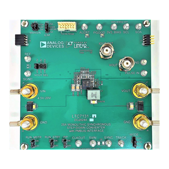
BOARD PHOTO
25A Monolithic Synchronous DC/DC Step-
Down Converter with PMBus Interface
DEMO MANUAL
LTpowerPlay allows users to monitor fault status and
real-time telemetry of input and output voltages, input
and output current, and internal IC die temperature.
Programmable parameters include device address, out-
put voltage, on/off control, and fault response to output
overvoltage and output overcurrent.
The LTC7131-1 data sheet gives a complete description
of this part, its operation and application information and
must be read in conjunction with this quick start guide
for DC2824A-A.
Design files for this circuit board are
All registered trademarks and trademarks are the property of their respective owners.
DC2824A-A
LTC7131-1
available.
Rev. 0
1
Advertisement
Table of Contents

Related Manuals for Analog Devices LTC7131-1


Summary of Contents for Analog Devices LTC7131-1
- Page 1 25A of load current. overvoltage and output overcurrent. The DC2824A-A powers up to default settings and pro- The LTC7131-1 data sheet gives a complete description duces power based on configuration resistors without the of this part, its operation and application information and...
-
Page 2: Performance Summary
QUICK START PROCEDURE Demonstration circuit 2824A-A is easy to set up to evalu- Notes ate the performance of the LTC7131-1. Refer to Figure 1 1. When measuring the output or input voltage for the proper measurement equipment setup and follow ripple, do not use the long ground lead on the the procedure below. -
Page 3: Test Setup Diagram
DEMO MANUAL DC2824A-A TEST SETUP DIAGRAM Figure 2. Proper Measurement Equipment Setup Rev. 0... -
Page 4: Test Results
DEMO MANUAL DC2824A-A TEST RESULTS 0.65V 1.2V 0.8V 1.8V 3.3V OUTPUT LOAD CURRENT (A) dc2824a-a F01 Figure 3. Efficiency vs load Current with V = 12V, f = 480kHz 5mV/DIV 5mV/DIV dc2824a-a G04b 2µs/DIV dc2824a-a G04a 2µs/DIV = 12V, I = 25A, f = 480kHz = 12V, I = 25A, f... -
Page 5: Thermal Image
You can use LTpowerPlay to evaluate LTC7880 and LTC7131-1’s demo system, or a customer Analog Devices ICs by connecting to a demo board sys- board. The software also provides an automatic update tem. LTpowerPlay can also be used in an off-line mode... - Page 6 The following procedure describes how to use LTpowerPlay b. After LTC7131-1 is detected, the LTpowerPlay to monitor and change the settings of LTC7131-1. main interface appears as shown in Figure 7, and a message box like below also shows for a...
- Page 7 LTC7131-1. Please make sure that the WP jumper (JP5) is at “OFF” position. d. The LTC7131-1 features the PMBus Lite with a reduced command list as shown below. The available commands include immediate/soft turn-off, turn-on or returning to normal opera-...
-
Page 8: Parts List
DIODE, SCHOTTKY, 30V, 100mA, SOD-323 CENTRAL SEMI., CMHSH-3 TR J2, J6-J8 EVAL BOARD STUD HARDWARE SET, #10-32 ANALOG DEVICES, 720-0010 IND., 215nH, PWR, FERRITE, 10%, 61A, 0.29mΩ, 10.4mm EATON, FP1007R3-R22-R × 8.0mm SMD XSTR., MOSFET, P-CH, 20V, 5.9A, TO-236 (SOT23-3) VISHAY, Si2365EDS-T1-GE3 XSTR., MOSFET N-CH, 60V, 300mA, SOT-23... - Page 9 PARTS LIST ITEM REFERENCE PART DESCRIPTION MANUFACTURER/PART NUMBER IC, 25A MONOLITHIC SYNCHRONOUS DC/DC STEP-DOWN ANALOG DEVICES, LTC7131IY-1#PBF CONVERTER WITH PMBus INTERFACE, BGA IC, MEMORY, EEPROM, 2Kb (256×8), TSSOP-8, 400kHz MICROCHIP , 24LC025-I/ST Additional Demo Board Circuit Components C6, C43 CAP ., OPTION, 0603 C8, COUT2, CAP ., OPTION, 1210...
-
Page 10: Schematic Diagram
DEMO MANUAL DC2824A-A SCHEMATIC DIAGRAM Rev. 0... - Page 11 Devices for its use, nor for any infringements of patents or other rights of third parties that may result from its use. Specifications subject to change without notice. No license is granted by implication or otherwise under any patent or patent rights of Analog Devices.
- Page 12 Board until you have read and agreed to the Agreement. Your use of the Evaluation Board shall signify your acceptance of the Agreement. This Agreement is made by and between you (“Customer”) and Analog Devices, Inc. (“ADI”), with its principal place of business at One Technology Way, Norwood, MA 02062, USA. Subject to the terms and conditions of the Agreement, ADI hereby grants to Customer a free, limited, personal, temporary, non-exclusive, non-sublicensable, non-transferable license to use the Evaluation Board FOR EVALUATION PURPOSES ONLY.
- Page 13 Mouser Electronics Authorized Distributor Click to View Pricing, Inventory, Delivery & Lifecycle Information: Analog Devices Inc. DC2824A-A...
Need help?
Do you have a question about the LTC7131-1 and is the answer not in the manual?
Questions and answers