Advertisement
Quick Links
DESCRIPTION
Demonstration circuit 2529A is a dual output synchro-
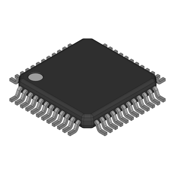
nous buck converter featuring the LTC
48-lead eLQFP package.
Key features of this board include: an optional on-board
NMOS LDO for DRVCC; jumper for spread-spectrum
option; optional resistors for single output dual phase
operation; a mode selector that allows the converter to
run in CCM, pulse-skipping, adjustable burst clamp or
default Burst Mode
operation; SYNC turret for Poly-
®
Phase
operation.
®
PERFORMANCE SUMMARY
Table 1.
PARAMETER
Input Voltage Range
Output Voltage V
OUT1
Output Voltage V
OUT2
Maximum Output Current I
OUT1,MAX
Maximum Output Current I
OUT2,MAX
Default Operating Frequency (Typical)
External Clock Sync. Frequency Range
Typical Full Load Efficiency (See Figure 4)
Document Feedback
DEMO MANUAL DC2529A
High Input Voltage Dual Output
Synchronous Buck Converter
The input voltage range of this demo board is from 16V to
7810ELXE in a
130V and it uses a sense resistor for overcurrent protec-
®
tion. The LTC7810 data sheet gives a complete descrip-
tion of the part, operation and application information and
must be read in conjunction with this demo manual for
DC2529A.
Design files for this circuit board are available at
http://www.analog.com/DC2529A
L, LT, LTC, LTM, Linear Technology, the Linear logo, Burst Mode and PolyPhase are registered
trademarks of Analog Devices, Inc. All other trademarks are the property of their respective
owners.
Specifications are at T
CONDITIONS
V
= 16V to 130V, I
= 0A to 10A, JP4: FCM
IN
OUT1
V
= 16V to 130V, I
= 0A to 5A, JP4: FCM
IN
OUT2
V
= 16V to 130V, I
IN
OUT1,MAX
V
= 16V to 130V, I
IN
OUT2,MAX
V
= 48V, V
= 5V, I
= 10A
IN
OUT1
OUT1
V
= 48V, V
= 12V, I
= 5A
IN
OUT2
OUT
For more information
www.analog.com
LTC7810ELXE
= 25°C
A
VALUE
16V to 130V
5V ± 2%
12V ± 2%
10A
5A
100kHz
75kHz to 750kHz
88.7%
95.4%
UG-1311 Rev 0
1
Advertisement

Related Manuals for Analog Devices LTC7810ELXE


Summary of Contents for Analog Devices LTC7810ELXE
- Page 1 ® L, LT, LTC, LTM, Linear Technology, the Linear logo, Burst Mode and PolyPhase are registered Phase operation. trademarks of Analog Devices, Inc. All other trademarks are the property of their respective ® owners. PERFORMANCE SUMMARY Specifications are at T = 25°C...
-
Page 2: Quick Start Procedure
QUICK START PROCEDURE Demonstration circuit DC2529A is easy to set up to 2. With power off, connect the input power supply to V evaluate the performance of the LTC7810ELXE. Refer to and GND. Figure 1 for proper measurement equipment setup and 3. - Page 3 DEMO MANUAL DC2529A QUICK START PROCEDURE – – LOAD SUPPLY – – LOAD – – DC2529A F01 Figure 1. Proper Measurement Equipment Setup – Figure 2. Measuring Input or Output Ripple Across Terminals or Directly Across Ceramic Capacitor UG-1311 Rev 0 For more information www.analog.com...
- Page 4 DEMO MANUAL DC2529A FREQUENCY SYNCHRONIZATION AND MODE SELECTION Demonstration circuit 2529A’s Mode selector allows the JP4. To synchronize the DC2529A to an external clock, converter to run in forced continuous operation, pulse- apply the sync signal to the PLLIN turret. Depending upon skipping operation, Burst Mode operation or Burst Mode the JP4 setting, the DC2529A will operate in different with adjustable clamp level by changing the position of...
- Page 5 DEMO MANUAL DC2529A = 24V = 24V = 48V = 48V = 72V = 72V = 100V = 100V = 130V = 130V DC2629A F03 DC2629A F04 Figure 3. DC2529A V Typical Figure 4. DC2529A V Typical OUT1 OUT2 FCM Efficiency vs Load Current FCM Efficiency vs Load Current OUT1 20MHz BW...
- Page 6 DEMO MANUAL DC2529A Figure 7. Thermal Image V 130V, V 5V at 10A, V 12V at 5A No Air Flow, T = 25°C OUT1 OUT2 UG-1311 Rev 0 For more information www.analog.com...
-
Page 7: Parts List
RES., 2.2, 1/10W, 1% 0603 VISHAY, CRCW06032R20FKEA R34, R36 RES., 100k, 1/10W, 1%, 0603 VISHAY, CRCW0603100KFKEA RES., 10k, 1/10W, 1%, 0603 VISHAY, CRCW060310K0FKEA RES., 1k, 1/10W, 1%, 0603 VISHAY, CRCW06031K00FKEA I.C., LTC7810ELXE#PBF , LQFP-7X7 LINEAR TECH., LTC7810ELXE#PBF UG-1311 Rev 0 For more information www.analog.com... - Page 8 DEMO MANUAL DC2529A PARTS LIST ITEM REFERENCE PART DESCRIPTION MANUFACTURER/PART NUMBER Additional Demo Board Circuit Components C17, C23, C28, C32, C33 CAP ., OPTION, 0603 C15, C26 CAP ., OPTION, 1210 CAP ., OPTION, 0805 D1, D2 DIODE, OPTION, DI-123 Q5, Q6, Q8 XSTR., OPTION R1, R4, R5, R13, R20, R28, R38 RES., 0Ω, 1/10W, 0603...
-
Page 9: Schematic Diagram
Devices for its use, nor for any infringements of patents or other rights of third parties that may result from its use. Specifications For more information www.analog.com subject to change without notice. No license is granted by implication or otherwise under any patent or patent rights of Analog Devices. - Page 10 Board until you have read and agreed to the Agreement. Your use of the Evaluation Board shall signify your acceptance of the Agreement. This Agreement is made by and between you (“Customer”) and Analog Devices, Inc. (“ADI”), with its principal place of business at One Technology Way, Norwood, MA 02062, USA. Subject to the terms and conditions of the Agreement, ADI hereby grants to Customer a free, limited, personal, temporary, non-exclusive, non-sublicensable, non-transferable license to use the Evaluation Board FOR EVALUATION PURPOSES ONLY.
Need help?
Do you have a question about the LTC7810ELXE and is the answer not in the manual?
Questions and answers