
Related Manuals for Stahl YL60 Series


Summary of Contents for Stahl YL60 Series
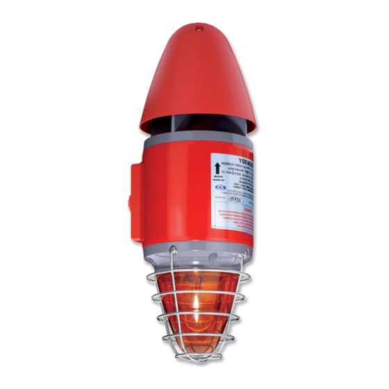
- Page 1 Operating instructions Additional languages r-stahl.com Audible and visual signalling device Series YL60...
-
Page 2: Table Of Contents
Contents Contents General information .....................3 Manufacturer......................3 Information regarding the operating instructions..........3 Further documents....................3 Conformity with standards and regulations............3 Explanation of symbols ..................3 Symbols used in these operating instructions............3 Warning notes......................4 Symbols on the device..................5 Safety notes ......................6 Operating instructions storage ................6 Personnel qualification..................6 Safe use.......................6 Modifications and alterations ................7... -
Page 3: En Fr
Publication code: 2022-07-11·BA00·III·en·05 Further documents • Data sheet For documents in other languages, see r-stahl.com. Conformity with standards and regulations IECEx, ATEX, EU Declaration of Conformity and further national certificates can be downloaded via the following link: https://r-stahl.com/en/global/support/downloads/. IECEx is also available at: http://iecex.iec.ch/... -
Page 4: Warning Notes
Explanation of symbols = Flashing beacon = Signal = Earth connection = Signal sound = Telephone connection Warning notes Warning notes must be observed under all circumstances, in order to minimise the risk resulting from design engineering and operation. The warning notes have the following structure: •... -
Page 5: Se Fi
Explanation of symbols Symbols on the device Symbol Meaning CE marking according to the current applicable directive. 05594E00 Device certified for hazardous areas according to the marking. 02198E00 Input 15649E00 Output 15648E00 Safety notes that must always be observed: The corresponding data and/or safety-related instructions contained in the operating instructions must be followed for devices with this symbol! 11048E00... -
Page 6: Safety Notes
Additional knowledge is required for any activity in hazardous areas! R. STAHL recommends having a level of knowledge equal to that described in the following standards: • IEC/EN 60079-14 (Project engineering, selection and construction of electrical systems) •... -
Page 7: Modifications And Alterations
Function and device design Commissioning, maintenance, repair • Only have commissioning and repairs performed by qualified and authorised persons (see chapter "Personnel qualification"). • Before commissioning, make sure that the device is not damaged. • Perform only maintenance work described in these operating instructions. Modifications and alterations DANGER Explosion hazard due to modifications and alterations to the device! -
Page 8: 5 Technical Data
Technical data Technical data Explosion protection Global (IECEx) Gas and dust IIB+H2 IECEx BAS 05.0087X IECEx BAS 05.0086X IIB+H2, IIB IEC 60079-0:2011 / IEC 60079-1:2014-06 / IEC 60079-31:2013 IIB+H2 Ex db IIB + H2 T4 Ta -20 to +60 °C Gb Ex tb IIIC T135 °C Ta -20 to +60 °C Db IP66 Ex db IIB + H2 T6 Ta -20 to +40 °C Gb Ex tb IIIC T85 °C Ta -20 to +40 °C Db IP66... - Page 9 Technical data Technical data Technical data Product weight 6 kg Electrical data Rated operational 24 V DC, 115 V AC, 230 V AC voltage Operational parameters +/- 10% Rated operational 24 V DC 570 mA current 115 V AC 200 mA 230 V AC 100 mA Ambient conditions...
-
Page 10: Transport And Storage
Service life Variant Number of flashes 2 million For further technical data, see r-stahl.com. Transport and storage • Transport and store the device only in the original packaging. • Store the device in a dry place (no condensation) free of vibrations. -
Page 11: Mounting And Installation
Mounting and installation Mounting and installation Dimensions/fastening dimensions Dimensional drawings (all dimensions in mm [inch]) – Subject to change 18380E00 222936 / YL6060300020 Audible and visual signalling device 2022-07-11·BA00·III·en·05 Series YL60... -
Page 12: Mounting/Dismounting, Operating Position
Mounting and installation Mounting/dismounting, operating position DANGER Explosion hazard due to improper mounting! Non-compliance results in severe or fatal injuries. • Only operate the device if it is not damaged. If the thread is damaged, replace the device immediately. • Only install the device in a clean and dry operating environment. •... -
Page 13: Installation
Mounting and installation • Mount the device on a flat surface suitable for its weight. • Direct tone output towards the area to be covered (see "Technical Data, Polar diagram" chapter). • Insert the electrical lines using a certified and flameproof cable entry which is suitable for the gas group. - Page 14 Mounting and installation 7.3.2 Electrical connections 15257E00 15258E00 YL60 DC YL60 AC Terminal blocks Plug for signalling device Sound selection switch (see tone table) Pins for combination function (DC version only) Pins plugged in: • Horn and flashing light function together.
- Page 15 Mounting and installation Parallel connection of several devices Up to 10 devices can be connected to a supply line in parallel. Circuit diagrams Line monitoring for devices with direct voltage • Through reverse polarity • By connecting an EOL resistor between 0 V and +V. The resistance value is defined by the system developer Two signal levels for devices with direct voltage •...
- Page 16 Mounting and installation Connection using a 2-wire conductor – second tone by reverse polarity 18404E00 18403E00 Sound 1 Sound 2 Horn and flashing light function separately Connection using a 4-wire conductor Remove jumper from LK1 and LK2 15266E00 Connection: • TB1 flashing •...
- Page 17 Mounting and installation AC version Combined horn and flashing light function with one signal tone Connection using a 2-wire conductor Bridge TB1 and TB2 using a conductor. 18405E00 Combined horn and flashing light function with two signal tones Connection using a 3-wire conductor 18407E00 18408E00 Sound 1...
- Page 18 Mounting and installation Horn and flashing light function together – activation by telephone signal The horn and flashing light are activated by a telephone signal. The function is retained as long as the telephone signal is available. The flashing light can flash up to four times after the telephone signal is deactivated.
- Page 19 Mounting and installation 7.3.3 Configuration The configuration of the device is performed by adjusting the DIP switch on the PCB. The following audible configuration options are available: Details of sound selection switch ON = 1 ON = 1 12345 12345 12345 15268E00 15269E00...
- Page 20 Mounting and installation Sou- SW1/SW2 Frequency Repetition rate Sound description Special application 720 Hz 0.7/0.3 s Interrupted sound Industrial alarm, Germany 700 Hz 0.25 s Interrupted sound Local warning, Sweden 700 Hz Interrupted sound Air-raid alarm, Sweden 1000 Hz Interrupted sound 700 Hz 6/12 s Interrupted sound Important...
- Page 21 Mounting and installation Sou- SW1/SW2 Frequency Repetition rate Sound description Special application 440 to 554 Hz Two alternating Turn out, tones Sweden (SS 031711) 2500 to 3200 Hz 0.07 s Two alternating tones 800 to 1000 Hz 0.13 s Two very quickly alternating tones 430 to 470 Hz Two alternating...
- Page 22 Mounting and installation 7.3.4 Mounting the device Inserting the PCB The correct position of the PCB is indicated by two grooves. Depending on the version, however, they can be in different positions as shown in the figure. 18814E00 18813E00 • YL60/./D50/./.. •...
- Page 23 Mounting and installation Screws and seals The cheese-head screws are delivered with Nyltite seals. • Before mounting, check the seals for damage. • Replace damaged seals. • Use seals a maximum of 5 times. • When using screws on a flat surface, note the seal on the screw head –...
-
Page 24: Commissioning
If an error occurs please re-visit the earlier sections of this document. If the error cannot be eliminated using the specified procedures: • Contact R. STAHL Schaltgeräte GmbH. For rapid processing, have the following information ready: • Type and serial number of the device •... -
Page 25: Ee 10 Maintenance, Overhaul, Repair
DANGER Explosion hazard due to improper repair! Non-compliance results in severe or fatal injuries. • Repair work on the devices must be performed only by R. STAHL Schaltgeräte GmbH. 222936 / YL6060300020 Audible and visual signalling device 2022-07-11·BA00·III·en·05 Series YL60... -
Page 26: 10.3 Returning The Device
• Only return or package the devices after consulting R. STAHL! Contact the responsible representative from R. STAHL. R. STAHL's customer service is available to handle returns if repair or service is required. • Contact customer service personally. • Go to the r-stahl.com website.
Need help?
Do you have a question about the YL60 Series and is the answer not in the manual?
Questions and answers