
Related Manuals for Stahl FX15 Series


Summary of Contents for Stahl FX15 Series
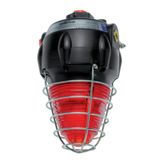
- Page 1 Operating instructions Additional languages r-stahl.com Visual signalling device Series FX15...
-
Page 2: Table Of Contents
Contents Contents General information .....................3 Manufacturer......................3 Information regarding the operating instructions..........3 Further documents....................3 Conformity with standards and regulations............3 Explanation of symbols ..................3 Symbols used in these operating instructions............3 Warning notes......................4 Symbols on the device..................5 Safety notes ......................6 Operating instructions storage ................6 Personnel qualification..................6 Safe use.......................6 Modifications and alterations ................7... -
Page 3: En Fr
They are legally binding in all legal affairs. Further documents • Data sheet For documents in other languages, see r-stahl.com. Conformity with standards and regulations IECEx, ATEX, EU Declaration of Conformity and further national certificates can be downloaded via the following link: https://r-stahl.com/en/global/support/downloads/. -
Page 4: Warning Notes
Explanation of symbols = Flashing beacon = Earth connection Warning notes Warning notes must be observed under all circumstances, in order to minimise the risk resulting from design engineering and operation. The warning notes have the following structure: • Signalling word: DANGER, WARNING, CAUTION, NOTICE •... -
Page 5: Symbols On The Device
Explanation of symbols Symbols on the device Symbol Meaning CE marking according to the current applicable directive. 05594E00 Device certified for hazardous areas according to the marking. 02198E00 Input 15649E00 Output 15648E00 Safety notes that must always be observed: The corresponding data and/or safety-related instructions contained in the operating instructions must be followed for devices with this symbol! 11048E00... -
Page 6: Safety Notes
Additional knowledge is required for any activity in hazardous areas! R. STAHL recommends having a level of knowledge equal to that described in the following standards: • IEC/EN 60079-14 (Project engineering, selection and construction of electrical systems) •... -
Page 7: Modifications And Alterations
Function and device design Commissioning, maintenance, repair • Only have commissioning and repairs performed by qualified and authorised persons (see chapter "Personnel qualification"). • Before commissioning, make sure that the device is not damaged. • Perform only maintenance work described in these operating instructions. Modifications and alterations DANGER Explosion hazard due to modifications and alterations to the device! -
Page 8: 5 Technical Data
Technical data Technical data Explosion protection Global (IECEx) Gas and dust IECEx BAS 13.0005X IECEx BAS 13.0003 IIB, IIC IEC 60079-0: 2011 / IEC 60079-1: 2014-06 / IEC 60079-31: 2013 Ex db IIB T* Gb (Ta = -60 to +** °C) Ex tb IIIC T*** °C Db IP 66 (Ta = -60 to +** °C) Ex db IIC T* Gb (Ta = -60 to +** °C) Ex tb IIIC T*** °C Db IP 66 (Ta = -60 to +** °C) - Page 9 Technical data Technical data Version 5 Joule xenon flashing beacon LED continuous beacon Technical data Product weight 2.4 kg Electrical data Rated operational 24 V DC, 48 V DC, 60 V DC, 24 V DC +/-10%, voltage 115 V AC, 240 V AC 100 to 254 V AC Operational parameters +/- 10% Rated operational...
-
Page 10: Transport And Storage
Screw terminal Connection terminals Solid: Max. 2.5 mm Finely stranded: Max. 2.5 mm For further technical data, see r-stahl.com. Transport and storage • Transport and store the device only in the original packaging. • Store the device in a dry place (no condensation) free of vibrations. -
Page 11: Mounting And Installation
Mounting and installation Mounting and installation Dimensions/fastening dimensions Dimensional drawings (all dimensions in mm [inch]) – Subject to change 105 mm / 4.13 " 78 mm / 3.07 " 152 mm / 5.98 " 78 mm / 3.07 " 137 mm / 5.39 " 180 mm / 7.09 "... -
Page 12: Mounting/Dismounting, Operating Position
Mounting and installation Mounting/dismounting, operating position DANGER Explosion hazard due to improper mounting! Non-compliance results in severe or fatal injuries. • Only operate the device if it is not damaged. If the thread is damaged, replace the device immediately. • Only install the device in a clean and dry operating environment. •... - Page 13 Mounting and installation NOTICE Malfunction or device damage from electrostatic discharge. Electronic components can be destroyed if touched. Non-compliance may lead to material damage! • Do not touch the LED PCBs! • Select a mounting location that is suitable for the signal effect of the device, as well as the required mounting and installation parameters (see "Technical data"...
-
Page 14: Installation
Mounting and installation Installation The electrical installation and configuration of the device is performed in the following sequence: • Dismounting the device (see chapter 7.3.1) • Electrical connections (see chapter 7.3.2) • Mounting the device (see chapter 7.3.3) • Mounting the earth connection (see chapter 7.3.4) 15755E00 Device base Seal... - Page 15 Mounting and installation 7.3.1 Dismounting the device The figure depicts the xenon flash tube variant for the FX15. The upper PCB components of the LED variant are different to the xenon variant. However, the fundamental structure of both products is the same. •...
- Page 16 Mounting and installation 7.3.2 Electrical connections 15756E00 15757E00 FX15 Lower FX15 PCB for xenon flash and LED variants Terminals Lower PCB PCB connector Lead wire Upper PCB Flash tube (not present with LED variants) Cable connection • Approx. 20 cm (8 inch) of electrical line are required for the connection of the circuit board within the enclosure.
- Page 17 Mounting and installation Parallel connection of several devices Up to 10 devices can be connected to a supply line in parallel. Circuit diagrams for xenon flash and LED variants AC version DC version TELEPHONE TELEPHONE INITIATE INITIATE 15759E00 15758E00 FX15 AC FX15 DC 218095 / FX1560300010 Visual signalling device...
- Page 18 Mounting and installation 7.3.3 Mounting the device • Connect the connector to the connection PCB. • Carefully place the top part (5) on the base. Take care to insert the structure straight into the base without applying force. 22940E00 • Secure the top part using the 6 cheese-head screws (6/TX20) (tightening torque 3 Nm).
- Page 19 Mounting and installation Screws and seals The cheese-head screws are delivered with Nyltite seals. • Before mounting, check the seals for damage. • Replace damaged seals. • Use seals a maximum of 5 times. • When using screws on a flat surface, note the seal on the screw head –...
-
Page 20: Commissioning
If an error occurs please re-visit the earlier sections of this document. If the error cannot be eliminated using the specified procedures: • Contact R. STAHL Schaltgeräte GmbH. For rapid processing, have the following information ready: • Type and serial number of the device •... -
Page 21: Ee 10 Maintenance, Overhaul, Repair
10.2 Repair DANGER Explosion hazard due to improper repair! Non-compliance results in severe or fatal injuries. • Repair work on the devices must be performed only by R. STAHL Schaltgeräte GmbH. 218095 / FX1560300010 Visual signalling device 2022-02-03·BA00·III·en·08 Series FX15... -
Page 22: 10.3 Returning The Device
• Only return or package the devices after consulting R. STAHL! Contact the responsible representative from R. STAHL. R. STAHL's customer service is available to handle returns if repair or service is required. • Contact customer service personally. • Go to the r-stahl.com website.
Need help?
Do you have a question about the FX15 Series and is the answer not in the manual?
Questions and answers