Table of Contents
Advertisement
Available languages
Available languages
Quick Links
GRP Kombinationssignal -
110 dB(A) / 5 Joule,
druckfest gekapselt
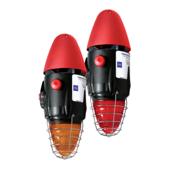
GRP Flameproof Combination Signal -
110 dB(A) / 5 Joule
Reihe YL6S
Series YL6S
Betriebsanleitung
Operating instructions
Additional languages www.stahl-ex.com
DE EN
DE
EN
EN
DE
EN
EN
DE
EN
EN
DE
EN
EN
DE
EN
EN
DE
EN
EN
DE
EN
EN
DE
EN
EN
DE
Advertisement
Chapters
Table of Contents

Related Manuals for Stahl YL6S Series


Summary of Contents for Stahl YL6S Series
- Page 1 Betriebsanleitung Operating instructions Additional languages www.stahl-ex.com DE EN GRP Kombinationssignal - 110 dB(A) / 5 Joule, druckfest gekapselt GRP Flameproof Combination Signal - 110 dB(A) / 5 Joule Reihe YL6S Series YL6S...
-
Page 3: De De De
Betriebsanleitung Additional languages www.stahl-ex.com GRP Kombinationssignal - 110 dB(A) / 5 Joule, druckfest gekapselt Reihe YL6S... -
Page 4: Table Of Contents
10.2 Reparatur ......................19 10.3 Rücksendung ....................19 Reinigung ......................19 Entsorgung ......................19 Zubehör und Ersatzteile ...................19 Allgemeine Angaben Hersteller R. STAHL Schaltgeräte GmbH R. STAHL Schaltgeräte GmbH Business Unit Lighting & Signalling Nordstr. 10 Am Bahnhof 30 99427 Weimar 74638 Waldenburg Germany Germany Tel.:... -
Page 5: Angaben Zur Betriebsanleitung
Diese ist rechtsverbindlich in allen juristischen Angelegenheiten. Weitere Dokumente • Datenblatt Weitere Sprachen, siehe www.stahl-ex.com. Konformität zu Normen und Bestimmungen Siehe Zertifikate und EG-Konformitätserklärung: www.stahl-ex.com. Das Gerät verfügt über eine IECEx-Zulassung. Siehe IECEx-Homepage: http://ie - cex.iec.ch/ Erläuterung der Symbole Symbole in der Betriebsanleitung... -
Page 6: Warnhinweise
Erläuterung der Symbole = Blitzleuchte = Signal = Erde = Signal Stufe 1 = Signal Stufe 2 = Signal Stufe 3 = Signalton = Telefonanschluss Warnhinweise Warnhinweise unbedingt befolgen, um das konstruktive und durch den Betrieb bedingte Risiko zu minimieren. Die Warnhinweise sind wie folgt aufgebaut: •... -
Page 7: Symbole Am Gerät
Sicherheitshinweise Symbole am Gerät Symbol Bedeutung CE-Kennzeichnung gemäß aktuell gültiger Richtlinie. 05594E00 Gerät gemäß Kennzeichnung für explosionsgefährdete Bereiche zertifiziert. 02198E00 Eingang 15649E00 Ausgang 15648E00 Sicherheitshinweise Aufbewahrung der Betriebsanleitung • Betriebsanleitung sorgfältig lesen und am Einbauort des Geräts aufbewahren. • Mitgeltende Dokumente und Betriebsanleitungen der anzuschließenden Geräte beachten. -
Page 8: Funktion
Funktion und Geräteaufbau Funktion Die Produktreihe YL6S liefert akustische und optische Alarmsignale, die zur Alarmierung, Warnung oder als Hinweis auf eine Gerätestörung/-start oder auf jegliche sicherheitstechnische Probleme hinweisen. Die akustischen und optischen Signale können unabhängig oder in Kombination betrieben werden. Das Gerät zeichnet sich durch seine Korrosionsbeständigkeit aus und ist daher besonders geeignet für den Einsatz in rauesten Umgebungen sowohl Onshore und Offshore. - Page 9 Technische Daten Technische Daten Explosionsschutz Global (IECEx) Gas und Staub IECEx BAS 14.0064 IEC 60079-0: 2011 / IEC 60079-1: 2007 / IEC 60079-31: 2013 Ex d IIB T* Ta -** ... +** °C Gb Ex d IIC T* Ta -** ... +** °C Gb Ex tb IIIC T*** °C Ta -** ...
-
Page 10: De Technische Daten
Technische Daten Technische Daten Stromaufnahme Kombinationsge Blitzleuchte Hupe rät 24 V DC 600 mA 320 mA 280 mA 48 V DC 420 mA 170 mA 250 mA 115 V AC 280 mA 204 mA 76 mA 230 V AC 115 mA 75 mA 40 mA * Ton 1... -
Page 11: De 6 Transport Und Lagerung
Transport und Lagerung Transport und Lagerung • Gerät nur in Originalverpackung transportieren und lagern. • Gerät trocken (keine Betauung) und erschütterungsfrei lagern. • Gerät nicht stürzen. Montage und Installation Maßangaben / Befestigungsmaße Maßzeichnungen (alle Maße in mm [Zoll]) - Änderungen vorbehalten Ø... -
Page 12: Montage / Demontage, Gebrauchslage
Montage und Installation Montage / Demontage, Gebrauchslage GEFAHR Explosionsgefahr! Gefahr von Verletzungen und Sachschäden! • Bei Verwendung von Aderendhülsen müssen diese unbedingt gasdicht mit geeignetem Werkzeug angebracht werden. GEFAHR Explosionsgefahr! Gefahr von Verletzungen und Sachschäden! • Die Komponenten sorgfältig entfernen oder austauschen. •... - Page 13 Montage und Installation 7.2.2 Montage mit Befestigungswinkel • Bügel an Wand anbringen • Gerät befestigen 17161E00 17162E00 1 Horn 2 Leiterplatte 3 Xenon-Blitz-Röhre 4 Dichtung 5 Flansch Blitzleuchte 6 Zylinderkopfschrauben M5 x 25 17158E00 • 6 x Zylinderkopfschrauben (6) lösen und Flansch der Blitzleuchte (5) entfernen Der Zugang zu den M5 Zylinderkopfschrauben ist durch den Schutzkorb verdeckt.
- Page 14 Montage und Installation 7.2.3 Zusammenbau des Gehäuses • Den Flansch der Blitzleuchte in Richtung Gerät anheben. • Die Leiterplatte mit Stecker anschließen. • Den Flansch der Blitzleuchte montieren. • Die Zylinderkopfschrauben M5 x 25 (siehe unten, Information) ersetzen und mit einen Drehmoment von 4 Nm anziehen.
- Page 15 Montage und Installation 1 Xenon-Blitz-Röhre 2 Blitzleiterplatte 17164E00 Schlüsselkomponenten YL6S • Die Xenon Blitzröhre während des Einbaus/Montage des Geräts nicht berühren. Kabelanschluss • Die Anschlussklemme ist für Kabel mit einem Querschnitt von 2,5 mm oder 14 ... 18 AWG geeignet. Parallelverbindung mehrere Geräte Bis zu 10 Geräte können parallel an einer Versorgungsleitung angeschlossen werden (siehe Verdrahtungsplan).
- Page 16 Montage und Installation TELEPHONE TELEPHONE INITIATE INITIATE NEUTRAL NEUTR LIVE (Vac) STROBE 24/48 Vdc STAGE AC/DC 17194E00 17193E00 Schaltplan Gleichspannungen Schaltplan Wechselspannungen = Blitzleuchte = Signal Stufe 1 = Signal Stufe 2 = Signal Stufe 3 7.2.5 Erdanschluss 17191E00 Erdungsanschluss Verwendung von metallischen Kabel- und Leitungseinführungen Eine Erdungsfahne ist für jedes Gerät vorgesehen.
- Page 17 Montage und Installation 7.2.6 Einstellbare Tonfolgen • Signaltonauswahl und deren Schalterpositionen: siehe Tabelle unten. • Kontrollieren der korrekten Schalterpositionen der ausgewählten Signaltöne Tontabelle Tonwahl- Wieder - Ausführung Häufigkeit schalter holfre - Sonderanwendung 12345 quenz (EIN = 1) (sec) Ton 01 Zwei alternierende Töne 800-1000 00000 Feueralarme - Bahnübergang Ton 02 Zwei alternierende Töne 2500-3100...
-
Page 18: De 7.3 Installation
Montage und Installation Tontabelle Ton 28 ISO 8201 Evakuierung 800-1000 11011 Als Stan - Internationaler Evakuierungs - dard alarm Ton 29 Schneller Heulton 500-1000 00111 0,15 Ton 30 Langsamer Heulton 500-1200 10111 Evakuierung, Niederlande Ton 31 Rückwärts-Sweep 1200-500 01111 Feueralarm, Deutschland (DIN 33404) Ton 32 Sirene 500-1200... -
Page 19: Betrieb
Tritt ein Fehler auf, lesen Sie bitte die vorherigen Abschnitte dieses Dokuments. Wenn sich der Fehler mit den genannten Vorgehensweisen nicht beheben lässt: • An R. STAHL Schaltgeräte GmbH wenden. Zur schnellen Bearbeitung folgende Angaben bereithalten: • Typ und Seriennummer •... -
Page 20: Instandhaltung, Wartung, Reparatur
Instandhaltung, Wartung, Reparatur Instandhaltung, Wartung, Reparatur WARNUNG Stromschlaggefahr bzw. Fehlfunktion des Geräts durch unbefugte Arbeiten! Nichtbeachten kann zu schweren Verletzungen und Sachschäden führen. • Arbeiten am Gerät ausschließlich von dazu autorisierter und entsprechend geschulter Elektro-Fachkraft ausführen lassen. 10.1 Instandhaltung Die geltenden nationalen Bestimmungen im Einsatzland beachten. •... -
Page 21: 10.2 Reparatur
R. STAHL Schaltgeräte GmbH ausführen lassen. 10.3 Rücksendung Für die Rücksendung im Reparatur-/Servicefall das Formular "Serviceschein" verwen - den. Auf der Internetseite "www.stahl-ex.com" im Menü "Downloads > Kundenservice": • Serviceschein herunterladen und ausfüllen. • Gerät zusammen mit dem Serviceschein wieder in der Originalverpackung an die R. - Page 23 Operating instructions Additional languages www.stahl-ex.com GRP Flameproof Combination Signal - 110 dB(A) / 5 Joule Series YL6S...
- Page 24 10.2 Repair .......................19 10.3 Returning the device ..................19 Cleaning ......................20 Disposal ......................20 Accessories and Spare parts ................20 General Information Manufacturer R. STAHL Schaltgeräte GmbH R. STAHL Schaltgeräte GmbH Business Unit Lighting & Signalling Nordstr. 10 Am Bahnhof 30 99427 Weimar 74638 Waldenburg...
-
Page 25: Information Regarding The Operating Instructions
Further documents • Data sheet For further languages, see www.stahl-ex.com. Conformity with standards and regulations See certificates and EC Declaration of Conformity: www.stahl-ex.com. The device has IECEx approval. See IECEx homepage: http://iecex.iec.ch/ Explanation of the symbols Symbols in these operating instructions... -
Page 26: Warning Notes
Explanation of the symbols = Strobe = Sounder = Earth = Sounder Stage 1 = Sounder Stage 2 Sounder Stage 3 = Sounder Tone = Telephone initiate Warning notes Warning notes must be observed under all circumstances, in order to minimize the risk due to construction and operation. -
Page 27: Symbols On The Device
Safety notes Symbols on the device Symbol Meaning CE marking according to the current applicable directive. 05594E00 According to marking, device certified for hazardous areas. 02198E00 Input 15649E00 Output 15648E00 Safety notes Operating instructions storage • Read the operating instructions carefully and store them at the mounting location of the device. -
Page 28: Function
Function and device design Function Product Series YL6S is designed to provide both an audible and visual alarm which can be used to alert, warn or draw attention to machine malfunction/start up or any number of safety related issues. The audible and visual signals can be operated independently or as a combination unit. - Page 29 Technical data Technical data Explosion Protection Global (IECEx) Gas and dust IECEx BAS 14.0064 IEC 60079-0: 2011 / IEC 60079-1: 2007 / IEC 60079-31: 2013 Ex d IIB T* Ta -** ... +** °C Gb Ex d IIC T* Ta -** ... +** °C Gb Ex tb IIIC T*** °C Ta -** ...
-
Page 30: En Technical Data
Technical data Technical Data Current consumption Combined Strobe only Sounder only function 24 V DC 600 mA 320 mA 280 mA 48 V DC 420 mA 170 mA 250 mA 115 V AC 280 mA 204 mA 76 mA 230 V AC 115 mA 75 mA 40 mA... -
Page 31: En 6 Transport And Storage
Transport and storage Transport and storage • Transport and store the device only in the original packaging. • Store the device in a dry place (no condensation) and vibration-free. • Do not drop the device. Mounting and installation Dimensions / fastening dimensions Dimensional Drawings (All Dimensions in mm [inches]) - Subject to Alterations Ø... -
Page 32: Mounting / Dismounting, Operating Position
Mounting and installation Mounting / dismounting, operating position DANGER Risk of explosion! Risk of injuries and material damage! • Terminal sleeves are fitted, they must be gas-tight and applied with a suitable tool. DANGER Explosion hazard! Risk of injuries and material damage! •... - Page 33 Mounting and installation 7.2.2 Installation with mounting bracket • Fix bracket to wall • Attach device 17161E00 17162E00 1 Horn 2 PCB 3 Xenon flash tube 4 Seal 5 Strobe flange 6 Cheese-head screws M5 x 25 17158E00 • Loosen 6 x cheese head screws (6) and remove strobe flange 6 x M5 (5) Access to the M5 cheese head screws is obscured by the wire guard.
- Page 34 Mounting and installation 7.2.3 Reassembly of Enclosure • Lift strobe flange towards device. • Connect PCB using the plug. • Install strobe flange. • Replace cheese-head screws M5 x 25 (see information below) and tighten the screws with a tightening torque of 4 Nm. •...
- Page 35 Mounting and installation 1 Xenon flash tube 2 Flash circuit board 17164E00 Key components YL6S • Do not touch the Xenon flash tube at anytime during the installation/assembly of the device. Cable Connection • The terminals accept wires of 2.5 mm2 or 14 ... 18 AWG. Interconnection of devices parallel Up to 10 devices with common supplies may be connected as a single system loop.
- Page 36 Mounting and installation TELEPHONE TELEPHONE INITIATE INITIATE NEUTRAL NEUTR LIVE (Vac) STROBE 24/48 Vdc STAGE AC/DC 17194E00 17193E00 Circuit diagram DC voltages Circuit diagram AC voltages = Strobe = Sounder Stage 1 = Sounder Stage 2 Sounder Stage 3 7.2.5 Earth Connection 17191E00 Earth connection Use of metallic cable glands...
- Page 37 Mounting and installation 7.2.6 Sound Tone Selection • For signal tone selection and its switch positions refer to the table below. • Check if the correct switch positions of the selected signal tones have been selected. Tone table Sound selection Repeti - Tone Version...
- Page 38 Mounting and installation Tone table Tone Interrupted tone 1000 11010 Tone Interrupted tone 01010 Air-raid alarm, Sweden Tone Interrupted tone 10010 0.25 Local warning, Sweden Tone Interrupted tone 00010 0.7/0.3 Industrial alarm, Ger - many Tone Interrupted, fast, rising 1400 11100 0.25 volume...
-
Page 39: Installation
Commissioning Installation WARNING Danger of electric shock due to energised parts! Non-compliance can result in severe or fatal injuries. • All connections and wiring must be disconnected from the power supply. • Secure the connections against unauthorized switching. DANGER Explosion hazard! Risk of injuries and material damage! •... -
Page 40: Troubleshooting
If an error occurs please re-visit the earlier sections of this document. If the error cannot be eliminated using the mentioned procedures: • Contact R. STAHL Schaltgeräte GmbH. For fast processing, have the following information ready: • Type and serial number •... -
Page 41: 10.2 Repair
10.3 Returning the device Use the "Service form" to return the device when repair/service is required. On the internet site "www.stahl-ex.com" under "Downloads > Customer service": • Download the service form and fill it out. • Send the device along with the service form in the original packaging to R. -
Page 42: Cleaning
Malfunction or damage to the device due to the use of non-original components. Non-compliance can result in material damage. • Use only original accessories and spare parts from R. STAHL Schaltgeräte GmbH. For accessories and spare parts, see data sheet on our homepage www.stahl-ex.com.
Need help?
Do you have a question about the YL6S Series and is the answer not in the manual?
Questions and answers