
Related Manuals for Stahl YA60/3 Series


Summary of Contents for Stahl YA60/3 Series
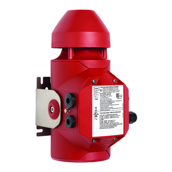
- Page 1 Operating instructions Additional languages r-stahl.com Audible signalling device Series YA60/3...
-
Page 2: Table Of Contents
Contents Contents General information .....................3 Manufacturer......................3 About these instructions..................3 Further documents....................3 Conformity with standards and regulations............3 Explanation of symbols ..................4 Symbols used in these operating instructions............4 Symbols on the device..................4 Safety........................5 Intended use ......................5 Personnel qualification..................6 Residual risks.......................6 Transport and storage..................8 Product selection and modification ..............9 Mounting and installation ...................12 Mounting/disassembling ..................12... -
Page 3: En Fr
Make the operating instructions accessible to operating and maintenance staff at all times. ▶ Pass the operating instructions on to each subsequent owner or user of the device. ▶ Update the operating instructions every time R. STAHL issues an amendment. ID no.: 292410 / YA6060300150 Publication code: 2023-11-03·BA00·III·en·00... -
Page 4: Explanation Of Symbols
Explanation of symbols Explanation of symbols Symbols used in these operating instructions Symbol Meaning Handy hint for making work easier Dangerous situation which can result in fatal or severe injuries DANGER! causing permanent damage if the safety measures are not complied with. -
Page 5: Se Fi
21 and 22, and in safe areas. "Intended use" includes complying with these operating instructions and the other applicable documents, e.g. the data sheet. All other uses are only intended after being approved by R. STAHL. 292410 / YA6060300150 Audible signalling device 2023-11-03·BA00·III·en·00... -
Page 6: Personnel Qualification
Unpack the device carefully to avoid damage. Make sure that no parts come loose inside the device. ▶ Check the packaging and the device for damage. Report any damage to R. STAHL immediately. Do not commission a damaged device. ▶... - Page 7 ▶ Do not change or modify the device. ▶ Repair work on the device must be performed only by R. STAHL. ▶ Gently clean the device with a damp cloth only – do not use scratching, abrasive or aggressive cleaning agents or solutions.
-
Page 8: Gr 4 Transport And Storage
Transport and storage 3.3.2 Risk of injury Falling devices or components The heavy device or components can fall during transport and mounting, causing severe injury to persons in the form of bruises and contusions. ▶ Adhere to the operator's safety regulations, e.g. regarding the use of personal protective equipment (safety shoes). -
Page 9: Product Selection And Modification
Product selection and modification Product selection and modification Variants The following variants of the Series YA60/3 signalling device are available: Horn: 23826E00 23827E00 Omnidirectional horn Directional horn Connection chamber: 23829E00 23828E00 Ex d connection chamber Ex e connection chamber 292410 / YA6060300150 Audible signalling device 2023-11-03·BA00·III·en·00 Series YA60/3... - Page 10 Product selection and modification Connection terminals Screw terminal Clamping range: 1 x 0.5 to 2.5 mm (finely stranded with and without core end sleeve) 1 x 0.5 to 4 mm (solid) (2 spare clamping units are available for each pole) The two connectional terminals on the neutral conductor/negative potential (DC) are bridged using a plug-in jumper.
- Page 11 Product selection and modification Push-in terminal Clamping range: 1 x 0.5 to 2.5 mm (finely stranded with and without core end sleeve) 1 x 0.5 to 4 mm (solid) (2 spare clamping units are available for each pole) The two connectional terminals on the neutral conductor/negative potential (DC) are bridged using a plug-in jumper.
-
Page 12: Mounting And Installation
Mounting and installation Mounting and installation Mounting/disassembling DANGER! Explosion hazard due to inadequate sealing on metal cable glands! Non-compliance results in fatal or severe injuries. ▶ Use a sealing ring (CMP, polyamide) for metal cable glands and Ex d/Ex e enclosures. ▶... - Page 13 Mounting and installation 6.1.2 Wall mounting Mounting the L-bracket When operating the signalling device with increased vibration requirements ("harsh operation", IEC/EN 60598-1), the L-bracket must be used as a retaining element. 23773E00 24186E00 ▶ Mount the L-bracket on the wall (1). ▶...
- Page 14 Mounting and installation 6.1.3 Disassembling ▶ 24189E00 Disconnect the device from the power supply before disassembling. ▶ Dismantle the device into its component parts, as shown in the figure. Audible signalling device 292410 / YA6060300150 Series YA60/3 2023-11-03·BA00·III·en·00...
-
Page 15: Installation
Mounting and installation Installation 6.2.1 Conductor connection ▶ Select suitable conductors that do not exceed the permissible heating temperature within the enclosure. ▶ Ensure that conductors have the specified cross sections (see the "Technical data" chapter). ▶ Guide the conductor insulation to the terminals (for the stripping length, see the "Technical data"... - Page 16 Mounting and installation 6.2.2.2 Wiring For an Ex e connection chamber: For an Ex d connection chamber: 23782E00 23778E00 ▶ ▶ Screw the cable entries into the drilled Screw the cable entries into the drilled holes provided. holes provided. While doing so, comply with the While doing so, comply with the regulations and approvals applicable to regulations and approvals applicable to...
- Page 17 Mounting and installation 6.2.2.3 Basic configuration ▶ Use the preconfigured functions (default setting) in the connection area via A/B control signals for static signal adaptation (using the plug-in jumper provided) or dynamic signal adaptation (using separate wiring). The plug-in jumper can be modified depending on the required configuration setting (individual pins can be disconnected).
- Page 18 Mounting and installation For an Ex d connection chamber: DANGER! Explosion hazard due to a missing or incorrectly attached M95 threaded cover! Non-compliance results in fatal or severe injuries. ▶ Always fit the M95 threaded cover because this is necessary to meet the requirements of the type of protection (tightening torque 8 Nm).
- Page 19 Mounting and installation 6.2.3 Advanced configuration options (optional) (see chapter 15.1 for general settings) 6.2.3.1 Opening the enclosure NOTICE! Malfunction or device damage when opening the audible flange! Non-compliance can result in material damage. ▶ Do not open the audible flange. ▶...
- Page 20 Mounting and installation ▶ 24196E00 Open the cover. Access to the configuration PCB is enabled. 23792E00 ▶ Configure the DIP switches present according to the necessary requirements. Four DIP switches are available for this: 1. Audible settings (tone 1/3/4) (see chapter 15.2 for the tone table) 2.
- Page 21 Mounting and installation 6.2.3.2 Mounting the cover DANGER! Explosion hazard due to a missing or incorrectly attached enclosure cover! Non-compliance results in fatal or severe injuries. ▶ Observe the installation note in the data sheet. ▶ Make sure that the O-ring is inserted and is not damaged. ▶...
-
Page 22: Commissioning
Commissioning ▶ 24289E00 Secure the cover with the TX20 safety screw (tightening torque 1.6 Nm). Commissioning Before commissioning, carry out the following checks: ▶ Check the mounting and installation. ▶ Check the device for damage. ▶ Remove any foreign objects. ▶... -
Page 23: Commissioning Multiple Devices
Commissioning Commissioning multiple devices 24206E00 Example: Connection diagram for combining multiple devices • If electrical conductors are connected to input signals A and/or B, these conductors must always be connected to a potential. - to the positive potential of the signalling device's input voltage, corresponding to a logic "1"... -
Page 24: Earthing/Protective Conductor
Perform overhaul of the device according to the applicable national regulations and the safety notes in these operating instructions ("Safety" chapter). Repair ▶ Repair work on the device must be performed only by R. STAHL. Audible signalling device 292410 / YA6060300150 Series YA60/3... -
Page 25: Returning The Device
Returning the device ▶ Only return or package the devices after consulting R. STAHL! Contact the responsible representative from R. STAHL. R. STAHL's customer service is available to handle returns if repair or service is required. ▶ Contact customer service personally. ▶... -
Page 26: Cn 13.1 Technical Data
Appendix A Appendix A 13.1 Technical data Explosion protection Global (IECEx) Gas and dust IECEx EPS 22.0046X Ex db IIC T4/T6 Ex db eb IIC T4/T6 Ex tb IIIC T80/T100 °C Europe (ATEX, UKEX) Gas and dust EPS 22 ATEX 1 224 X, CML 21UKEX1224X E II 2 G Ex db IIC T4/T6 E II 2 G Ex db eb IIC T4/T6 E II 2 D Ex tb IIIC T80/T100 °C... - Page 27 Appendix A Technical data Technical data Product weight 6 kg Electrical data Rated operational Horn: 12 to 27.2 V DC voltage Average input power/ Max. current Input power Max. input power max. current consumption (temporary) consumption [mA] Horn 1000 Class I (with internal PE connection) Ambient conditions Functional ambient...
- Page 28 Scope of delivery Signalling device according to configuration 1 x L-/U-bracket 4 x stopping plugs 1 x plug-in jumper 2 x cable entries (for Ex de) For further technical data, see r-stahl.com. Audible signalling device 292410 / YA6060300150 Series YA60/3 2023-11-03·BA00·III·en·00...
-
Page 29: Device Design
Appendix B Appendix B 14.1 Device design Device element Bracket (retaining cable) M95 threaded cover Screws Connection chamber cover Horn cover Enclosure External earth connection 24198E00 Cover Ex d Device element Bracket (retaining cable) Screws Connection chamber cover Horn cover Enclosure External earth connection Cover... -
Page 30: Dimensions/Fastening Dimensions
Appendix B 14.2 Dimensions/fastening dimensions Dimensional drawings (all dimensions in mm [inch]) – Subject to change 23796E00 211,80 [ 8,34] Ø Ø 23797E00 Omnidirectional horn Directional horn Audible signalling device 292410 / YA6060300150 Series YA60/3 2023-11-03·BA00·III·en·00... -
Page 31: General Settings
Appendix C Appendix C (Advanced configuration options) 15.1 General settings All switches are set to OFF ex-factory. DIP switch 4 Function Switches the device function on via the input voltage Switches the device function on via the B control signal (min. 10.8 V) A/B control for audible signal active A/B control for audible signal inactive –... -
Page 32: Tone Table
Appendix C 15.2 Tone table If the device activation via the B control signal is active (see chapter 15.1 for general settings), only two channels (tones) are available via the A control signal. Audible settings DIP switches 1 and 2 Tone no. - Page 33 Appendix C Description of tone no. Tone no. Horn attachment Description of tone Note Omni dB(A) dB(A) 108.2 114.7 Alternating tones UK, BS5839-1 at 2 Hz (800 Hz/1000 Hz, (fire alarm/ 0.25s 0.25s 0.25 s/0.25 s) level crossing) 24054E00 104.6 114.4 Alternating tones at 2 Hz (2500 Hz/3100 Hz,...
- Page 34 Appendix C Tone no. Horn attachment Description of tone Note Omni dB(A) dB(A) 106.7 115.1 Alternating tones at 0.16 Hz 0.5s (2040 Hz/1632 Hz, 22571E00 0.31 s/0.31 s) 103.8 113.0 Continuous tone 22580E00 (2300 Hz) 109.5 112.1 Continuous tone 22580E00 (440 Hz) 109.0 115.3...
- Page 35 Appendix C Tone no. Horn attachment Description of tone Note Omni dB(A) dB(A) 99.1 108.2 Interrupted tone Sweden, 0.5s at 4 Hz (700 Hz, SS 031711 22584E00 0.125 s on/0.125 s off) (emergency signal) 100.3 109.5 Interrupted tone Germany 0.7s 0.3s at 1 Hz (700 Hz, (industrial alarm)
- Page 36 Appendix C Tone no. Horn attachment Description of tone Note Omni dB(A) dB(A) 103.2 109.6 Continuous tone Germany 22580E00 (500 Hz) KTA 3901 (all-clear signal) IMO, Code 2 (Low) 98.0 106.7 Continuous tone Sweden, 22580E00 (660 Hz) SS 031711 (all-clear signal) 102.9 111.9 Continuous tone...
- Page 37 Appendix C Tone no. Horn attachment Description of tone Note Omni dB(A) dB(A) 108.0 115.7 Siren at 0.18 Hz (560/1055 Hz, 2.73 s/2.73 s) 2,753s 2,753s 24060E00 109.6 117.7 Siren at 1 Hz (660/1200 Hz, 0.5 s/0.5 s) 24061E00 106.9 112.8 Siren at 7 Hz (800/1000 Hz,...
- Page 38 Appendix C Tone no. Horn attachment Description of tone Note Omni dB(A) dB(A) 108.7 115.1 Interrupted tone IMO Code 1a at 0.5 Hz (1000 Hz, 24070E00 1 s on/1 s off) 7 x + continuous tone (1000 Hz, 7 s) 103.0 112.0 Interrupted tone...
Need help?
Do you have a question about the YA60/3 Series and is the answer not in the manual?
Questions and answers