
Subscribe to Our Youtube Channel
Related Manuals for Nexcom NDiS V1100


Summary of Contents for Nexcom NDiS V1100
- Page 1 NEXCOM International Co., Ltd. Intelligent Platform & Services Business Unit Digital Signage Platform NDiS V1100 User Manual NEXCOM International Co., Ltd. www.nexcom.com Published July 2022...
-
Page 2: Table Of Contents
SATA Power Connector ..............16 Physical Features ..................4 80 Debug Port Connector ..............17 Front Panel ..................4 Battery Connector ................17 Rear Panel ...................4 M.2 2280_2242 Connector (M-key) ..........18 Mechanical Dimensions ................5 Copyright © 2022 NEXCOM International Co., Ltd. All Rights Reserved. NDiS V1100 User Manual... - Page 3 When to Configure the BIOS ..............36 Default Configuration ................37 Entering Setup ..................37 Legends ....................37 BIOS Setup Utility ..................39 Main ....................39 Advanced ..................40 Security .....................46 Boot ....................47 Save & Exit ..................47 Copyright © 2022 NEXCOM International Co., Ltd. All Rights Reserved. NDiS V1100 User Manual...
-
Page 4: Preface
No describes how to keep the system CE compliant. part of this manual may be reproduced, copied, translated or transmitted in any form or by any means without the prior written consent from NEXCOM Declaration of Conformity International Co., Ltd. -
Page 5: Rohs Compliance
(Cr6+) < 0.1% or 1,000ppm, Polybrominated biphenyls (PBB) < 0.1% or 1,000ppm, and Polybrominated diphenyl Ethers (PBDE) < 0.1% or 1,000ppm. In order to meet the RoHS compliant directives, NEXCOM has established an engineering and manufacturing task force to implement the introduction of green products. -
Page 6: Warranty And Rma
“NEXCOM RMA Service Form” for the RMA number apply process. ▪ If RMA goods can not be repaired, NEXCOM will return it to the customer without any charge. ▪ Customers can send back the faulty products with or without accessories (manuals, cable, etc.) and any components from the card, such as CPU... - Page 7 ESD workstation. If no such station is available, you can provide some ESD protection by wearing an antistatic wrist strap and attaching it to a metal part of the computer chassis. Copyright © 2022 NEXCOM International Co., Ltd. All Rights Reserved. NDiS V1100 User Manual...
-
Page 8: Safety Information
There is a danger of explosion if battery is incorrectly replaced. Replace only with the same or equivalent type recommended by the manufacturer. Discard used batteries according to the manufacturer’s instructions. viii Copyright © 2022 NEXCOM International Co., Ltd. All Rights Reserved. NDiS V1100 User Manual... -
Page 9: Safety Precautions
12. Never pour any liquid into an opening. This may cause fire or electrical minimum and altitude 2000m, if further assistance is needed, please shock. contact NEXCOM International Co., Ltd. further information. Copyright © 2022 NEXCOM International Co., Ltd. All Rights Reserved. NDiS V1100 User Manual... -
Page 10: Technical Support And Assistance
Preface Technical Support and Assistance Conventions Used in this Manual 1. For the most updated information of NEXCOM products, visit NEXCOM’s Warning: website at www.nexcom.com. Information about certain situations, which if not observed, can cause personal injury. This will prevent injury to yourself 2. -
Page 11: Global Service Contact Information
Tel: +886-2-8226-7786 Tel: +886-2-8976-3077 Beitun District, Fax: +886-2-8226-7782 Email: sales@diviotec.com Taichung City, 406, Taiwan, R.O.C. Email: services@tmrtek.com www.diviotec.com Tel: +886-4-2249-1179 www.tmrtek.com Fax: +886-4-2249-1172 Email: jacobhuang@nexaiot.com www.nexaiot.com Copyright © 2022 NEXCOM International Co., Ltd. All Rights Reserved. NDiS V1100 User Manual... - Page 12 9F, Tamachi Hara Bldg., LongGang District, 4-11-5, Shiba Minato-ku, ShenZhen, 518112, China Tokyo, 108-0014, Japan Tel: +86-755-8364-7768 Tel: +81-3-5419-7830 Fax: +86-755-8364-7738 Fax: +81-3-5419-7832 Email: steveyang@nexcom.com.tw Email: sales@nexcom-jp.com www.nexcom.cn www.nexcom-jp.com Copyright © 2022 NEXCOM International Co., Ltd. All Rights Reserved. NDiS V1100 User Manual...
-
Page 13: Package Contents
Preface Package Contents Before continuing, verify that the NDiS V1100 package that you received is complete. Your package should have all the items listed in the following table. Item Part Number Name Description 5060200638X00 Thermal Pad Thermal Pad For Neu-X300-Q370-F65 Ver:A S.W... -
Page 14: Ordering Information
Preface Ordering Information The following below provides ordering information for NDiS V1100. ▪ NDiS V1100-i3 (P/N: 10W00110000X0) 11th Gen Intel Core™ i3-1115G4E processor fanless system, ® 0°C~45°C ▪ NDiS V1100-i5 (P/N: 10W00110001X0) 11th Gen Intel Core™ i5-1145G7E processor fanless system, ®... -
Page 15: Chapter 1: Product Introduction
▪ Dual LAN ports and 3 x USB 3.0 ports ▪ Onboard M.2 2280 Key M with PCIe x4 signal for storage modules ▪ Onboard mini-PCIe for optional Wi-Fi or LTE modules ▪ Fanless design Copyright © 2022 NEXCOM International Co., Ltd. All Rights Reserved. NDiS V1100 User Manual... -
Page 16: Hardware Specifications
1 x M.2 2280 Key M (PCIe Gen4 x4, SATA III), support optional storage ▪ 2 x DB9 modules ▪ 1 x SATA & SATA power connector - COM1: RS232/422/485 - COM2: RS232 Copyright © 2022 NEXCOM International Co., Ltd. All Rights Reserved. NDiS V1100 User Manual... - Page 17 ▪ CE Approval ▪ FCC Class A Dimensions ▪ 190mm (W) x 165mm (D) x 51.1mm (H) (without wall mount bracket) Operating System Support ▪ Win10/Linux Copyright © 2022 NEXCOM International Co., Ltd. All Rights Reserved. NDiS V1100 User Manual...
-
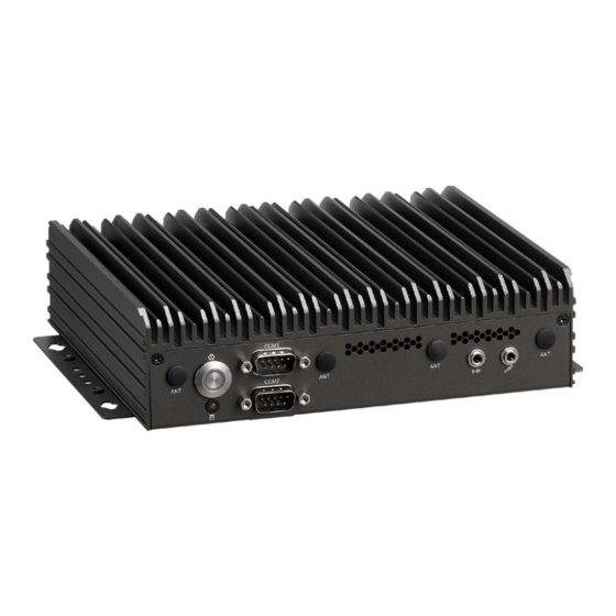
Page 18: Physical Features
Antenna Hole Antenna Hole Antenna Hole Antenna Hole USB 2.0 Power Button 12V DC Input COM Port Line Out HDMI USB 3.1 Storage LED Mic In Copyright © 2022 NEXCOM International Co., Ltd. All Rights Reserved. NDiS V1100 User Manual... -
Page 19: Mechanical Dimensions
Chapter 1: Product Introduction Mechanical Dimensions Copyright © 2022 NEXCOM International Co., Ltd. All Rights Reserved. NDiS V1100 User Manual... -
Page 20: Chapter 2: Jumpers And Connectors
Static electricity can damage many of the electronic ▪ Use correct screws and do not over tighten screws. components. Humid environments tend to have less static electricity than Copyright © 2022 NEXCOM International Co., Ltd. All Rights Reserved. NDiS V1100 User Manual... -
Page 21: Jumper Settings
(on) and open (off). Two-Pin Jumpers: Open (Left) and Short (Right) Three-Pin Jumpers: Pins 1 and 2 are Short Copyright © 2022 NEXCOM International Co., Ltd. All Rights Reserved. NDiS V1100 User Manual... -
Page 22: Locations Of The Jumpers And Connectors
The figure below shows the locations of the jumpers and connectors. USB3_1 USB3_2 LAN_2 LAN_1 HDMI_2 HDMI_1 Top View HDDLED1 USB2_78P USB2_901P SATA PWR1 COM1 COM2 GPIO RSTCON MINI_CARD CPUFAN MIC_LOUT DIMM1 Copyright © 2022 NEXCOM International Co., Ltd. All Rights Reserved. NDiS V1100 User Manual... -
Page 23: Bottom View
Chapter 2: Jumpers and Connectors Bottom View Copyright © 2022 NEXCOM International Co., Ltd. All Rights Reserved. NDiS V1100 User Manual... -
Page 24: Jumpers
Connector type: 1x3 3-pin header Connector location: AT_ATX Connector location: CLRCMOS Settings Settings 1-2 On AT Mode 1-2 On Normal (Default) 2-3 On ATX Mode (Default) 2-3 On Clear CMOS Copyright © 2022 NEXCOM International Co., Ltd. All Rights Reserved. NDiS V1100 User Manual... -
Page 25: Internal Connectors
HDD LED Header Connector type: 1x2 2-pin header System Reset Connector location: HDDLED1 Connector type: 1x2 2-pin header Connector location: RSTCON Definition Definition HDD_LED+ RESET# HDD_LED- Copyright © 2022 NEXCOM International Co., Ltd. All Rights Reserved. NDiS V1100 User Manual... -
Page 26: Power Led Header
RI Connector Connector type: 1x2 2-pin header Connector type: 1x5 5-pin header Connector location: JP2 Connector location: JP1 Definition Definition Definition COM1_RI PWR_LED- COM1_RI PWR_LED+ +12V Copyright © 2022 NEXCOM International Co., Ltd. All Rights Reserved. NDiS V1100 User Manual... -
Page 27: Mic & Line Out Connector
Connector type: 1x9 9-pin header Connector type: 1x2 2-pin header Connector location: MIC_LOUT Connector location: J1 Definition Definition Definition LOUT_R LOUT_JD LOUT_L PWRBTN# MIC_R MIC_JD MIC_L Copyright © 2022 NEXCOM International Co., Ltd. All Rights Reserved. NDiS V1100 User Manual... -
Page 28: Fan Connector
Connector type: 1x4 4-pin header Connector type: 1x9 9-pin header Connector location: CPUFAN Connector location: COM1, COM2 Definition Definition Definition Definition +12V FAN SPEED DETECT FAN SPEED CONTROL Copyright © 2022 NEXCOM International Co., Ltd. All Rights Reserved. NDiS V1100 User Manual... -
Page 29: Internal Usb2.0 X2 Port
SATA Connector Connector type: 1x6 6-pin header Connector location: SATA Connector location: USB2_78P, USB2_910P Definition Definition Definition Definition USB2N SATA_TXP USB2P USB1N SATA_TXN USB1P SATA_RXN SATA_RXP Copyright © 2022 NEXCOM International Co., Ltd. All Rights Reserved. NDiS V1100 User Manual... -
Page 30: Gpio Connector
Connector type: 1x10 10-pin header Connector type: 1x2 2-pin header Connector location: GPIO1 Connector location: PWR1 Definition Definition Definition GPIO_PIN3 GPIO_PIN4 GPIO_PIN5 GPIO_PIN6 GPIO_PIN7 GPIO_PIN8 GPIO_PIN9 GPIO_PIN10 Copyright © 2022 NEXCOM International Co., Ltd. All Rights Reserved. NDiS V1100 User Manual... -
Page 31: 80 Debug Port Connector
Connector type: 1x10 10-pin header Connector type: 1x2 2-pin header Connector location: 80PORT Connector location: BAT Definition Definition Definition PLTRST# ESPI_CLK ESPI_CS# ESPI_IO3 ESPI_IO2 ESPI_IO1 ESPI_IO0 ESPI_RST# 3.3V Copyright © 2022 NEXCOM International Co., Ltd. All Rights Reserved. NDiS V1100 User Manual... -
Page 32: 2280_2242 Connector (M-Key)
SATA_RXN(PCIE1_RXN) M2M_LED# PCIE4_RXN +3VSB SATA_TXN(PCIE1_TXN) PCIE4_RXP +3VSB SATA_TXP(PCIE1_TXP) RESET# +3VSB CLKREQ# PCIE3_RXN +3VSB CLK_PCIEN WAKE# PCIE3_RXP CLK_PCIEP PCIE3_RXN PCIE3_RXP M2M_PEDET +3VSB PCIE2_RXN +3VSB PCIE2_RXP +3VSB PCIE2_RXN Copyright © 2022 NEXCOM International Co., Ltd. All Rights Reserved. NDiS V1100 User Manual... -
Page 33: 2242 Connector (B-Key)
PCIE_TXP RESET(3.3V) CLKREQ# PCIE4_RXP +3VSB CLK_DN WAKE# CLK_DP CONFIG0 WWAN_GPS_ON USB3_RXN UIM_RESET USB3_RXP UIM_CLK RESET(1.8V) SUS_CLK UIM_DATA CONFIG1 3.3V USB3_TXN UIM_PWR 3.3V USB3_TXP DEVSLP 3.3V CONFIG2 Copyright © 2022 NEXCOM International Co., Ltd. All Rights Reserved. NDiS V1100 User Manual... -
Page 34: Mini Pcie Card
USB2_6DP 3.3V 1.5V 3.3V CLKREQ# UIM_PWR UIM_DATA CLKN0 UIM_CLK 1.5V CLKP0 UIM_RESET UIM_VPP 3.3V 3.3V W_DIS# RESET# PCIE5_RXN 3.3V PCIE5_RXP 1.5V SMB_CLK PCIE5_TXN SMB_DATA PCIE5_TXP USB2_6DN Copyright © 2022 NEXCOM International Co., Ltd. All Rights Reserved. NDiS V1100 User Manual... -
Page 35: External Connectors
HDMI1_TX2P Definition Definition +12VSUS +12VSUS HDMI2_TX2N HDMI1_TX2N HDMI2_TX1P HDMI1_TX1P CGND HDMI2_TX1N HDMI1_TX1N HDMI2_TX0P HDMI1_TX0P HDMI2_TX0N HDMI1_TX0N HDMI2_CLKP HDMI1_CLKP HDMI2_CLKN HDMI1_CLKN HDMI2_SCL HDMI1_SCL HDMI2_SDA HDMI1_SDA HDMI2_HPD HDMI1_HPD Copyright © 2022 NEXCOM International Co., Ltd. All Rights Reserved. NDiS V1100 User Manual... -
Page 36: Lan Connector
Definition Definition MDI_0P MDI_0N MDI_0P MDI_0N MDI_1P MDI_1N MDI_1P MDI_1N MDI_2P MDI_2N MDI_2P MDI_2N MDI_3P MDI_3N MDI_3P MDI_3N LINK1000# LINK100# +3VSB ACTLED# ACTLED# +3VSB LINK1000# LINK100# Copyright © 2022 NEXCOM International Co., Ltd. All Rights Reserved. NDiS V1100 User Manual... -
Page 37: Usb 3.0 Connector
Connector location: USB3_1 Definition Definition Definition Definition USB2_1N USB2_3N USB2_1P USB2_3P USB3_RX1N USB3_RX1P USB3_RX3N USB3_RX3P USB3_TX1N USB3_TX3N USB3_TX1P USB3_TX3P USB2_2N USB2_2P USB2_4N USB2_4P USB3_RX2N USB3_RX2P USB3_TX2N USB3_TX2P Copyright © 2022 NEXCOM International Co., Ltd. All Rights Reserved. NDiS V1100 User Manual... -
Page 38: Block Diagram
4 Pin DC Jack ATX 4 Pin External Connector (+12V) (+12V) Super I/O NCT6126D Internal Connector COM2 GPIO WatchDog F81439 HW Montior (RS232) 4 in/4 out Timer COM1 (RS232/422/485) Copyright © 2022 NEXCOM International Co., Ltd. All Rights Reserved. NDiS V1100 User Manual... -
Page 39: Chapter 3: System Setup
1. The screws on the bottom, front and rear sides are used to secure the cover to the chassis. Remove these screws and put them in a safe place for later use. Front Bottom Rear Copyright © 2022 NEXCOM International Co., Ltd. All Rights Reserved. NDiS V1100 User Manual... - Page 40 Chapter 3: System Setup 2. Open the memory cover on the bottom by removing two screws, then remove the other two screws on the main board inside it. Copyright © 2022 NEXCOM International Co., Ltd. All Rights Reserved. NDiS V1100 User Manual...
- Page 41 Chapter 3: System Setup 3. With the screws removed, lift up the cover and remove it from the chassis. Copyright © 2022 NEXCOM International Co., Ltd. All Rights Reserved. NDiS V1100 User Manual...
-
Page 42: Installing A So-Dimm Memory Module
You will hear a distinctive “click” sound, indicating the module is correctly locked into position. SO-DIMM Copyright © 2022 NEXCOM International Co., Ltd. All Rights Reserved. NDiS V1100 User Manual... -
Page 43: Installing An M.2 Storage Module (M Key 2280)
1. Locate the M.2 M key slot on the board. 2. Remove the screw on the board. Store the screw in a safe place for later use. M.2 M Key Slot Copyright © 2022 NEXCOM International Co., Ltd. All Rights Reserved. NDiS V1100 User Manual... - Page 44 Then push the module down and secure it with the screw removed in step 2. Copyright © 2022 NEXCOM International Co., Ltd. All Rights Reserved. NDiS V1100 User Manual...
-
Page 45: Installing An M.2 5G/4G Module (B Key 3052 Or 3042 W/ Bracket)
1. Locate the M.2 B key slot on the board. 2. Remove the screw on the board. Store the screw in a safe place for later use. Copyright © 2022 NEXCOM International Co., Ltd. All Rights Reserved. NDiS V1100 User Manual... - Page 46 Copyright © 2022 NEXCOM International Co., Ltd. All Rights Reserved. NDiS V1100 User Manual...
-
Page 47: Installing A Wi-Fi And Bluetooth Card (Minipcie)
Installing a Wi-Fi and Bluetooth card (miniPCIe) 1. Locate the mini-PCIe slot on the board. 2. Remove the screw on the board. Store the screw in a safe place for later use. Copyright © 2022 NEXCOM International Co., Ltd. All Rights Reserved. NDiS V1100 User Manual... - Page 48 Copyright © 2022 NEXCOM International Co., Ltd. All Rights Reserved. NDiS V1100 User Manual...
-
Page 49: Wall Mount Installation
1. Align the M4 mounting holes on the chassis cover to the desired installation location. Then mount the system by fastening 4 screws through the mounting holes. Copyright © 2022 NEXCOM International Co., Ltd. All Rights Reserved. NDiS V1100 User Manual... -
Page 50: Chapter 4: Bios Setup
This chapter describes how to use the BIOS setup program for NDiS V1100. The settings made in the setup program affect how the computer performs. The BIOS screens provided in this chapter are for reference only and may It is important, therefore, first to try to understand all the setup options, and change if the BIOS is updated in the future. -
Page 51: Default Configuration
Powering on the computer and immediately pressing <Del> allows you to enter Setup. Load optimized default values. Press the key to enter Setup: Saves and exits the Setup program. Press <Enter> to enter the highlighted sub-menu Copyright © 2022 NEXCOM International Co., Ltd. All Rights Reserved. NDiS V1100 User Manual... - Page 52 When “” appears on the left of a particular field, it indicates that a submenu which contains additional options are available for that field. To display the submenu, move the highlight to that field and press Copyright © 2022 NEXCOM International Co., Ltd. All Rights Reserved. NDiS V1100 User Manual...
-
Page 53: Bios Setup Utility
F3: Optimized Defaults PCH SKU U Premium ESC: Exit F4: Save & Exit Stepping ESC: Exit Version 2.22.1282 Copyright (C) 2022 AMI Version 2.22.1282 Copyright (C) 2022 AMI Copyright © 2022 NEXCOM International Co., Ltd. All Rights Reserved. NDiS V1100 User Manual... -
Page 54: Advanced
F4: Save & Exit ESC: Exit Select USB power state in S5. Pending operation Version 2.22.1282 Copyright (C) 2022 AMI Schedules an operation for the security device. Copyright © 2022 NEXCOM International Co., Ltd. All Rights Reserved. NDiS V1100 User Manual... - Page 55 Configures the performance state that the BIOS will set before OS handoff. C States Enables or disables CPU power management. Allows CPU to go to C states when it’s not 100% utilized. Copyright © 2022 NEXCOM International Co., Ltd. All Rights Reserved. NDiS V1100 User Manual...
- Page 56 Enables or disables BIOS support for security device. O.S will not show SATA Test Mode Security Device. TCG EFI protocol and INT1A interface will not be available. Enables or disables SATA test mode. Copyright © 2022 NEXCOM International Co., Ltd. All Rights Reserved. NDiS V1100 User Manual...
- Page 57 Displays the Super I/O chip used on the board. ACPI Sleep State Select the highest ACPI sleep state the system will enter when the suspend button is pressed. Copyright © 2022 NEXCOM International Co., Ltd. All Rights Reserved. NDiS V1100 User Manual...
- Page 58 Detects and displays the current CPU core temperature. System Temperature Detects and displays the current system temperature. CPU FAN Speed Detects and displays the current CPU fan speed. Copyright © 2022 NEXCOM International Co., Ltd. All Rights Reserved. NDiS V1100 User Manual...
- Page 59 Enables or disables IPv6 PXE support. If disabled, the IPv6 boot option will USB Mass Storage Driver Support not be created. Enables or disables USB mass storage device driver support. Copyright © 2022 NEXCOM International Co., Ltd. All Rights Reserved. NDiS V1100 User Manual...
-
Page 60: Security
Version 2.22.1282. Copyright (C) 2022 AMI Version 2.22.1282. Copyright (C) 2022 AMI Administrator Password Select this to reconfigure the administrator’s password. User Password Select this to reconfigure the user’s password. Copyright © 2022 NEXCOM International Co., Ltd. All Rights Reserved. NDiS V1100 User Manual... -
Page 61: Boot
<ESC> to exit without saving the changes. Restore Defaults To restore the BIOS to default settings, select this field then press <Enter>. A dialog box will appear. Confirm by selecting Yes. Copyright © 2022 NEXCOM International Co., Ltd. All Rights Reserved. NDiS V1100 User Manual...
Need help?
Do you have a question about the NDiS V1100 and is the answer not in the manual?
Questions and answers