
Related Manuals for Nexcom NDiS M335


Summary of Contents for Nexcom NDiS M335
- Page 1 NEXCOM International Co., Ltd. Multi-Media Solutions Digital Signage Platform NDiS M335 User Manual NEXCOM International Co., Ltd. www.nexcom.com Published September 2015...
-
Page 2: Table Of Contents
Front Panel ..................2 Internal Connectors ................16 Rear Panel ...................2 Mini-PCIe Connector ..............16 Hardware Specifications ................3 SATA Connector (7-pin and 15-pin) ..........17 Mechanical Dimensions ................4 Battery Connector ................17 Copyright © 2015 NEXCOM International Co., Ltd. All Rights Reserved. NDiS M335 User Manual... - Page 3 Main ....................34 Advanced ..................35 Security .....................42 Boot ....................42 Save & Exit ..................43 Appendix A: Watchdog Timer........ 44 Appendix B: DASh Function........45 Appendix C: Supported Display Resolutions..47 Copyright © 2015 NEXCOM International Co., Ltd. All Rights Reserved. NDiS M335 User Manual...
-
Page 4: Preface
No describes how to keep the system CE compliant. part of this manual may be reproduced, copied, translated or transmitted in any form or by any means without the prior written consent from NEXCOM Declaration of Conformity International Co., Ltd. -
Page 5: Rohs Compliance
(Cr6+) < 0.1% or 1,000ppm, Polybrominated biphenyls (PBB) < 0.1% or 1,000ppm, and Polybrominated diphenyl Ethers (PBDE) < 0.1% or 1,000ppm. In order to meet the RoHS compliant directives, NEXCOM has established an engineering and manufacturing task force to implement the introduction of green products. -
Page 6: Warranty And Rma
(manuals, cable, etc.) and any components from the card, such as CPU and RAM. If the components were suspected as part of the problems, ▪ If RMA goods can not be repaired, NEXCOM will return it to the customer please note clearly which components are included. Otherwise, NEXCOM without any charge. - Page 7 ESD workstation. If no such station is available, you can provide some ESD protection by wearing an antistatic wrist strap and attaching it to a metal part of the computer chassis. Copyright © 2015 NEXCOM International Co., Ltd. All Rights Reserved. NDiS M335 User Manual...
-
Page 8: Safety Information
There is a danger of explosion if battery is incorrectly replaced. Replace only with the same or equivalent type recommended by the manufacturer. Discard used batteries according to the manufacturer’s instructions. viii Copyright © 2015 NEXCOM International Co., Ltd. All Rights Reserved. NDiS M335 User Manual... -
Page 9: Safety Precautions
RECOMMENDED BY THE MANUFACTURER. DISCARD USED BATTERIES ACCORDING TO THE MANUFACTURER’S INSTRUCTIONS. 10. All cautions and warnings on the equipment should be noted. Copyright © 2015 NEXCOM International Co., Ltd. All Rights Reserved. NDiS M335 User Manual... -
Page 10: Technical Support And Assistance
Preface Technical Support and Assistance Conventions Used in this Manual 1. For the most updated information of NEXCOM products, visit NEXCOM’s Warning: website at www.nexcom.com. Information about certain situations, which if not observed, can cause personal injury. This will prevent injury to yourself 2. -
Page 11: Global Service Contact Information
13F, No.920, Chung-Cheng Rd., ZhongHe District, Beijing, 100094, China New Taipei City, 23586, Taiwan, R.O.C. Tel: +86-010-5704-2680 Tel: +886-2-8226-7796 Fax: +86-010-5704-2681 Fax: +886-2-8226-7792 Email: sales@nexcom.cn Email: sales@nexcom.com.tw www.nexcom.cn www.nexcom.com.tw Copyright © 2015 NEXCOM International Co., Ltd. All Rights Reserved. NDiS M335 User Manual... - Page 12 Wuhan, 430070, China Building 11, 599 Yunling Road, Putuo District, Shanghai, 200062, China Tel: +86-27-8722-7400 Tel: +86-21-6125-8282 Fax: +86-27-8722-7400 Fax: +86-21-6125-8281 Email: sales@nexcom.cn Email: frankyang@nexcom.cn www.nexcom.cn www.nexcom.cn Copyright © 2015 NEXCOM International Co., Ltd. All Rights Reserved. NDiS M335 User Manual...
-
Page 13: Package Contents
Preface Package Contents Before continuing, verify that the NDiS M335 package that you received is complete. Your package should have all the items listed in the following table. Item Part Number Name Description 50311F0112X00 (H)Flat Head Screw Long Fei:F3x4iso For SPC-150 M3x4mm (Nylok) Black... -
Page 14: Ordering Information
Preface Ordering Information The following below provides ordering information for NDiS M335. NDiS M335 (P/N: 10W00M33500X0) Intel Celeron N3150 processor SoC OPS ® ® Test board kit (Optional) OPS-TB-KIT (P/N: 10QOPSTB00X1) Copyright © 2015 NEXCOM International Co., Ltd. All Rights Reserved. -
Page 15: Chapter 1: Product Introduction
Processor N3150 (formerly condenamed “Braswell”. NDiS M335 can be plugged into any OPS-complaint display devices to render rich multimedia contents. Thanks to the modular and cable-less, NDiS M335 OPS player satisfies the need for quick deployment and hassle free maintenance of large digital signage network dispersed in different geographical locations. -
Page 16: Physical Features
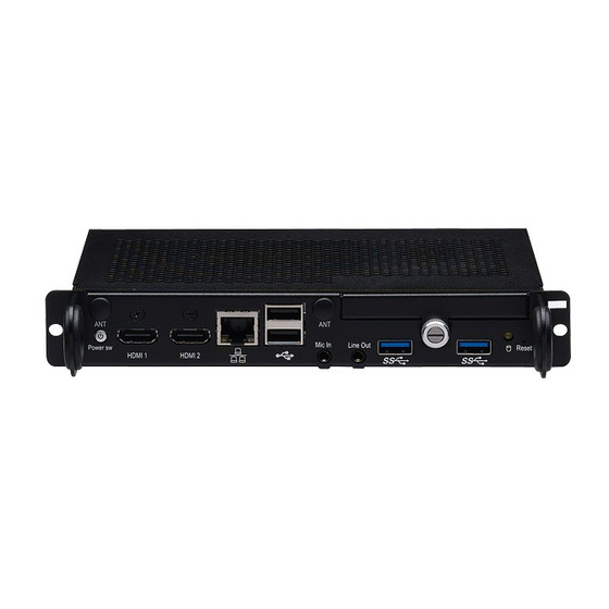
Antenna hDD LED hDMI1 hDMI2 USB 2.0 hDD Slot Power Mic-in Line-out Reset JAE TX25 80Pin 12~19V DC Input Button Button (For testing purposes) USB 3.0 Copyright © 2015 NEXCOM International Co., Ltd. All Rights Reserved. NDiS M335 User Manual... -
Page 17: Hardware Specifications
▪ 1 x Audio out L/R ▪ 2 x USB 2.0 ▪ 1 x USB 3.0 ▪ DC input +12V~+19V ▪ Control signals (PWR_STATUS, PS_ON#, PB_DET, CEC, SYS_FAN) Copyright © 2015 NEXCOM International Co., Ltd. All Rights Reserved. NDiS M335 User Manual... -
Page 18: Mechanical Dimensions
Chapter 1: Product Introduction Mechanical Dimensions Copyright © 2015 NEXCOM International Co., Ltd. All Rights Reserved. NDiS M335 User Manual... -
Page 19: Chapter 2: Jumpers And Connectors
Static electricity can damage many of the electronic ▪ Use correct screws and do not over tighten screws. components. Humid environments tend to have less static electricity than Copyright © 2015 NEXCOM International Co., Ltd. All Rights Reserved. NDiS M335 User Manual... -
Page 20: Locations Of The Jumpers And Connectors For Ndib M335
Locations of the Jumpers and Connectors for NDiB M335 NDiB M335 The figure below is the top and bottom view of the NDiB M335 mainboard which is the mainboard used in the NDiS M335. It shows the locations of the jumpers and connectors. -
Page 21: Bottom View
Chapter 2: Jumpers and Connectors Bottom View CN11 CN10 Copyright © 2015 NEXCOM International Co., Ltd. All Rights Reserved. NDiS M335 User Manual... -
Page 22: Jumper Settings
(on) and open (off). Two-Pin Jumpers: Open (Left) and Short (Right) Three-Pin Jumpers: Pins 1 and 2 are Short Copyright © 2015 NEXCOM International Co., Ltd. All Rights Reserved. NDiS M335 User Manual... -
Page 23: Jumpers
Connector type: 1x2 2-pin DIP switch Connector location: SW1 Status Settings Short Normal ON (1-4) Short Clear BIOS ON (2-3) Short Clear ME 1-2 On: default Copyright © 2015 NEXCOM International Co., Ltd. All Rights Reserved. NDiS M335 User Manual... -
Page 24: Connector Pin Definitions
Connector location: SW2 Connector location: CN6 and CN7 Definition Definition Definition Definition PWR_BTN# HDMI1_TX2P PWR_BTN# HDMI1_TX2N HDMI1_TX1P PWRLED_N PWRLED_P HDMI1_TX1N HDMI1_TX0P HDMI1_TX0N HDMI1_CLK_P HDMI1_CLK_N HDMI1_SCL HDMI1_SDA HDMI1_P5V HDMI1_HPD Copyright © 2015 NEXCOM International Co., Ltd. All Rights Reserved. NDiS M335 User Manual... -
Page 25: Lan Port
Connector location: LAN1 Connector location: CN3 Definition Definition Definition Definition LAN2_MDI3N USB2_5V USB_DN2 LAN1_MDI3P LAN1_MDI2N USB_DP2 LAN1_MDI2P LAN1_MDI1N USB2_5V USB_DN1 LAN1_MDI1P LAN1_MDI0N USB_DP1 LAN1_MDI0P LAN1_LED1P LAN1_LED_ACT# LAN1_LED2P LAN1_LED3P Copyright © 2015 NEXCOM International Co., Ltd. All Rights Reserved. NDiS M335 User Manual... -
Page 26: Usb 3.0 Port
Connector type: USB 3.0 port, Type A Connector location: LED2 Connector location: CN4 and CN5 Definition Definition Definition USB01_P5V USB_DN0 HD_LED USB_DP0 SATA_LED_V3P3# USB_RX0N USB_RX0P USB_TX0N USB_TX0P Copyright © 2015 NEXCOM International Co., Ltd. All Rights Reserved. NDiS M335 User Manual... -
Page 27: Reset Button
Reset Button Line-in Connector Connector location: SW3 Connector type: 3.5mm TRS Connector location: CN11 Definition Definition Definition Definition RST_BTN# AUDGND AUDGND LINE_INR LINE_INL PWRLED_N LIMIC_JD G1,G2 AUDGND Copyright © 2015 NEXCOM International Co., Ltd. All Rights Reserved. NDiS M335 User Manual... -
Page 28: Line-Out Connector
Chapter 2: Jumpers and Connectors Line-out Connector Connector type: 3.5mm TRS Connector location: CN10 Definition Definition AUDGND AUDGND LINE_OUTR LINE_OUTL SURR_JD G1,G2 AUDGND Copyright © 2015 NEXCOM International Co., Ltd. All Rights Reserved. NDiS M335 User Manual... -
Page 29: Jae-Tx25
HDMI0_CEC 40 HDMI0_TX2N DDP_0N HDMI0_TX2P SYS_FAN_EN# 46 PS_ON# 19 DDP_0P COM1_RXD 46 PWR_STATUS HDMI0_SDA COM1_TXD 46 DDP_AUXN HDMI0_SCL DDP_AUXP HDMI0_HPD USB_RX2N DDP_HPD USB_RX2P VIN_M HDMI0_CLK_N VIN_M USB_TX2N Copyright © 2015 NEXCOM International Co., Ltd. All Rights Reserved. NDiS M335 User Manual... -
Page 30: Internal Connectors
Definition WAKE# +V3.3A_MIN D15VS SMB_CLK D15VS PETn0 SMB_DATA CLKREQ# PETp0 USB_D- REFCLK- USB_D+ REFCLK+ +V3.3A_MIN +V3.3A_MIN LED_WWAN# LED_WLAN# DISABLE# LED_WPAN# PERST# D15VS PERn0 +V3.3A_MIN PERp0 +V3.3A_MIN Copyright © 2015 NEXCOM International Co., Ltd. All Rights Reserved. NDiS M335 User Manual... -
Page 31: Sata Connector (7-Pin And 15-Pin)
Connector type: Standard Serial ATA 7P and 15P Connector type: 1x2 2-pin header JST, 1.25mm pitch Connector location: SATA1 Connector location: J4 Definition Definition Definition Definition SATA_TXPO_C SATA_TXNO_C SATA_RXNO_C SATA_RXNO_C SATA_DET# Copyright © 2015 NEXCOM International Co., Ltd. All Rights Reserved. NDiS M335 User Manual... -
Page 32: Debug Port
Connector type: 1x4 4-pin header, 1.25mm pitch Connector location: J3 Connector location: FAN1 Definition Definition Definition Definition P80_RST# +12V CLK_PCI_P80 LPC_FRAME# FAN_TACT FAN_CTRL LPC_AD3 LPC_AD2 LPC_AD1 LPC_AD0 3VSB 3VSB Copyright © 2015 NEXCOM International Co., Ltd. All Rights Reserved. NDiS M335 User Manual... -
Page 33: Sim Card Slot
Chapter 2: Jumpers and Connectors SIM Card Slot Connector location: CN8 Definition Definition SIM_VCC SIM_RST SIM_CLK SIM_VPP SIM_IO Copyright © 2015 NEXCOM International Co., Ltd. All Rights Reserved. NDiS M335 User Manual... -
Page 34: Chapter 3: System Setup
1. The screws on the back and sides are used to secure the cover to the chassis. Remove these screws and put them in a safe place for later use. Copyright © 2015 NEXCOM International Co., Ltd. All Rights Reserved. NDiS M335 User Manual... -
Page 35: Installing A So-Dimm Memory Module
Installing a SO-DIMM Memory Module 1. At the bottom of the system, loosen the screws on the bottom cover and NDiS M335 supports two channels of SO-DIMM. If you want to install a remove it from the chassis. single memory module, please install to DIMM2 first. - Page 36 The ejector tabs at the ends of the socket will automatically snap into module can be plugged into the socket in only one direction. the locked position to hold the module in place. Ejector Notch Copyright © 2015 NEXCOM International Co., Ltd. All Rights Reserved. NDiS M335 User Manual...
-
Page 37: Installing A 2.5" Hdd Storage
1. Remove the HDD cover located at the front panel by loosening the screw. Screw Screw 4. Put the HDD back into the slot gently, then tighten the screw to secure it. Copyright © 2015 NEXCOM International Co., Ltd. All Rights Reserved. NDiS M335 User Manual... -
Page 38: Installing A Ngff (B/M Key) Ssd (Sata Interface)
1. Remove the screws on the back and sides of the system and then remove the chassis top cover. Put the screws in a safe place for later use. Copyright © 2015 NEXCOM International Co., Ltd. All Rights Reserved. NDiS M335 User Manual... - Page 39 2. Remove the screws securing the HDD bracket and then remove the 3. Locate the NGFF slot and insert the NGFF SSD module into the slot. bracket. NGFF slot Copyright © 2015 NEXCOM International Co., Ltd. All Rights Reserved. NDiS M335 User Manual...
- Page 40 Chapter 3: System Setup 4. Fasten a screw into the standoff to secure the NGFF SSD module. Copyright © 2015 NEXCOM International Co., Ltd. All Rights Reserved. NDiS M335 User Manual...
-
Page 41: Installing A Wireless Lan Module
1. At the bottom of the system, loosen the screws on the bottom cover and 2. Locate the mini-PCIe slot and insert the Wi-Fi module into the slot. remove it from the chassis. Screw Mini-PCIe slot Copyright © 2015 NEXCOM International Co., Ltd. All Rights Reserved. NDiS M335 User Manual... - Page 42 4. Attach the RF cables onto the Wi-Fi module and wire the cables to the on the module to secure it. top side of the mainboard. Screw RF cable Copyright © 2015 NEXCOM International Co., Ltd. All Rights Reserved. NDiS M335 User Manual...
- Page 43 6. Turn to the top side of the mainboard and mount the Wi-Fi antenna jacks to the Wi-Fi antenna holes located at the front panel of the chassis then tighten the rings. Ring1 Ring2 Copyright © 2015 NEXCOM International Co., Ltd. All Rights Reserved. NDiS M335 User Manual...
- Page 44 Chapter 3: System Setup 7. Connect the external antennas to the Wi-Fi antenna jacks. Antenna Copyright © 2015 NEXCOM International Co., Ltd. All Rights Reserved. NDiS M335 User Manual...
-
Page 45: Chapter 4: Bios Setup
This chapter describes how to use the BIOS setup program for the NDiS M335. The settings made in the setup program affect how the computer performs. The BIOS screens provided in this chapter are for reference only and may It is important, therefore, first to try to understand all the setup options, and change if the BIOS is updated in the future. -
Page 46: Default Configuration
Powering on the computer and immediately pressing <Del> allows you to enter Setup. Load optimized default values. Press the key to enter Setup: Saves and exits the Setup program. Press <Enter> to enter the highlighted sub-menu Copyright © 2015 NEXCOM International Co., Ltd. All Rights Reserved. NDiS M335 User Manual... - Page 47 When “” appears on the left of a particular field, it indicates that a submenu which contains additional options are available for that field. To display the submenu, move the highlight to that field and press Copyright © 2015 NEXCOM International Co., Ltd. All Rights Reserved. NDiS M335 User Manual...
-
Page 48: Bios Setup Utility
F2: Previous Values F3: Optimized Defaults F4: Save & Exit System Date [Mon 08/10/2015] ESC: Exit System Time [19:21:53] Version 2.17.1249. Copyright (C) 2015 American Megatrends, Inc. Copyright © 2015 NEXCOM International Co., Ltd. All Rights Reserved. NDiS M335 User Manual... -
Page 49: Advanced
Select the highest ACPI sleep state the system will enter when the suspend button is pressed. The options are Suspend Disabled and S3 (Suspend to RAM). Copyright © 2015 NEXCOM International Co., Ltd. All Rights Reserved. NDiS M335 User Manual... - Page 50 Select AC power state when power is re-applied after a power failure. USB Wake Up Enables or disables wake up from USB devices. Realtek LAN Card DASh Function Enables or disables Realtek LAN card DASH function. Copyright © 2015 NEXCOM International Co., Ltd. All Rights Reserved. NDiS M335 User Manual...
- Page 51 Version 2.17.1249. Copyright (C) 2015 American Megatrends, Inc. Serial Port Super IO Chip Enables or disables the serial port. Displays the Super I/O chip used on the board. Copyright © 2015 NEXCOM International Co., Ltd. All Rights Reserved. NDiS M335 User Manual...
-
Page 52: Cpu Configuration
CPU Temperature(DTS) Detects and displays the current CPU temperature. System Temperature Detects and displays the current system temperature. VCORE to VCC3 Detects and displays the output voltages. Copyright © 2015 NEXCOM International Co., Ltd. All Rights Reserved. NDiS M335 User Manual... - Page 53 Port 0 to Port 1 Enables or disables SATA port 0 to port 1. hot Plug Enables or disables hot plugging feature on SATA port 0 to port 1. Copyright © 2015 NEXCOM International Co., Ltd. All Rights Reserved. NDiS M335 User Manual...
- Page 54 Enables or disables IPv4 PXE support. If disabled, the IPv4 boot option will not be created. IPv6 PXE Support Enables or disables IPv6 PXE support. If disabled, the IPv6 boot option will not be created. Copyright © 2015 NEXCOM International Co., Ltd. All Rights Reserved. NDiS M335 User Manual...
- Page 55 Configures which drives the system can boot from. Network Enables or disables the boot option for legacy network devices. Video Enables or disables the boot option for legacy video devices. Copyright © 2015 NEXCOM International Co., Ltd. All Rights Reserved. NDiS M335 User Manual...
-
Page 56: Security
Adjust the boot sequence of the system. Boot Option #1 is the first boot device that the system will boot from, next will be #2 and so forth. Copyright © 2015 NEXCOM International Co., Ltd. All Rights Reserved. NDiS M335 User Manual... -
Page 57: Save & Exit
<ESC> to exit without saving the changes. Restore Defaults To restore the BIOS to default settings, select this field then press <Enter>. A dialog box will appear. Confirm by selecting Yes. Copyright © 2015 NEXCOM International Co., Ltd. All Rights Reserved. NDiS M335 User Manual... -
Page 58: Appendix A: Watchdog Timer
PPendIx atChdog Imer NDiS M335 features a watchdog timer that resets the CPU or generates an interrupt if the processor stops operating for any reason. This feature ensures system reliability in industrial standalone or unmanned environments. Watchdog Timer Control Register... -
Page 59: Appendix B: Dash Function
• Add account ESC: Exit • Del account • Assign role • Modify password Version 2.17.1249. Copyright (C) 2015 American Megatrends, Inc. Serial over LAN (text console redirection) Copyright © 2015 NEXCOM International Co., Ltd. All Rights Reserved. NDiS M335 User Manual... - Page 60 The software is provided in the driver CD and can also be downloaded from NEXCOM’s website. 1. Standard DASH_SDK, Ver. 1.2. 2. NEXCOM sample code and tool. 3. Realtek management console tool (free). Copyright © 2015 NEXCOM International Co., Ltd. All Rights Reserved. NDiS M335 User Manual...
-
Page 61: Appendix C: Supported Display Resolutions
Appendix C: Supported Display Resolutions C: s PPendIx uPPorted IsPlay esolutIons Port TX25 (TMDS) hDMI1 hDMI2 Max. Resolution 3840 x 2160 1920 x 1080 3840 x 2160 Copyright © 2015 NEXCOM International Co., Ltd. All Rights Reserved. NDiS M335 User Manual...
Need help?
Do you have a question about the NDiS M335 and is the answer not in the manual?
Questions and answers